1997 SSANGYONG KORANDO catalytic converter
[x] Cancel search: catalytic converterPage 458 of 2053

1F2 -- 40 M161 ENGINE CONTROLS
D AEW OO M Y_2000
FUEL SYSTEM
The function of the fuel metering system is to deliver the correct amount of fuel to the engine under all operating condi-
tions. The fuel is delivered to the engine by the individual fuel injectors mounted into the intake manifold near each
cylinder.
The main fuel control sensors are the Mass Air Flow (MAF) sensor and the oxygen (O2) sensors.
The MAF sensor monitors the mass flow of the air being drawn into the engine. An electrically heated element is
mounted in the intake air stream, where it is cooled by the flow of incoming air. Engine Control Module (ECM) modu-
lates the flow of heating current to maintain the temperature differential between the heated film and the intake air at a
constant level. The amount of heating current required to maintain the temperature thus provides an index for the
mass air flow. This concept automatically compensates for variations in air density, as this is one of the factors that
determines the amount of warmth that the surrounding air absorbs from the heated element. MAF sensor is located
between the air filter and the throttle valve.
Under high fuel demands, the MAF sensor reads a high mass flow condition, such as wide open throttle. The ECM
uses this information to enrich the mixture, thus increasing the fuel injector on-- time, to provide the correct amount of
fuel. When decelerating, the mass flow decreases. This mass flow change is sensed by the MAF sensor and read by
the ECM, which then decreases the fuel injector on-- time due to the low fuel demand conditions.
The O2 sensors are located in the exhaust pipe before catalytic converter. The O2 sensors indicate to the ECM the
amount of oxygen in the exhaust gas, and the ECM changes the air/fuel ratio to the engine by controlling the fuel
injectors. The best air/fuel ratio to minimize exhaust emissions is 14.7 to 1, which allows the catalytic converter to
operate most efficiently. Because of the constant measuring and adjusting of the air/fuel ratio, the fuel injection system
is called a “closed loop” system.
The ECM uses voltage inputs from several sensors to determine how much fuel to provide to the engine. The fuel is
delivered under one of several conditions, called ‘‘modes”.
Starting Mode
When the ignition is turned ON, the ECM turns the fuel pump relay on for 1 second. The fuel pump then builds fuel
pressure. The ECM also checks the Engine Coolant Temperature (ECT) sensor and the Throttle Position (TP) sensor
and determines the proper air/fuel ratio for starting the engine. This ranges from 1.5 to 1 at -- 36°C(--33°F) coolant
temperature to 14.7 to 1 at 94°C (201°F) coolant temperature. The ECM controls the amount of fuel delivered in the
starting mode by changing how long the fuel injector is turned on and off. This is done by ‘‘pulsing” the fuel injectors for
very short times.
Run Mode
The run mode has two conditions called ‘‘open loop” and ‘‘closed loop”.
Open Loop
When the engine is first started and it is above 690 rpm, thesystem goes into “open loop” operation. In “open loop”, the
ECM ignores the signal from the HO2S and calculates the air/fuel ratio based on inputs from the ECT sensor and the
MAF sensor. The ECM stays in “open loop” until the following conditions are met:
DThe O2 has a varying voltage output, showing that it is hot enough to operate properly.
DThe ECT sensor is above a specified temperature (22.5°C).
DA specific amount of time has elapsed after starting the engine.
Closed Loop
The specific values for the above conditions vary with different engines and are stored in the Electronically Erasable
Programmable Read -- Only Memory (EEPROM). When these conditions are met, thesystem goes into “closed loop”
operation. In “closed loop”, the ECM calculates the air/fuel ratio (fuel injector on-- time) based on the signals from the
O2 sensors. This allows the air/fuel ratio to stay very close to 14.7 to 1.
Acceleration Mode
The ECM responds to rapid changes in throttle position and airflow and provides extra fuel.
Deceleration Mode
The ECM responds to changes in throttle position and airflow and reduces the amount of fuel. When deceleration is
very fast, the ECM can cut off fuel completely for short periods of time.
Page 496 of 2053

1F2 -- 78 M161 ENGINE CONTROLS
D AEW OO M Y_2000
EXHAUST SYSTEM
CATALYTIC CONVERTER
The purpose of the catalytic converter is to convert the three pollutants of carbon monoxide (CO), hydrocarbons (HC)
and oxides of nitrogen (NOx) contained in the exhaust of gasoline engines, into the harmless compounds of water
(H2O), carbon dioxide (CO2) and nitrogen (N2).
The catalytic converter contains a catalyst, a word coming from the Greek and which designates the element essential
for catalyst which triggers chemical reactions without itself being consumed.
These catalysts in the 3 -- way catalytic converter are the rare metals platinum (Pt) and rhodium (Rh).
The catalytic converter consists essentially of three main elements. The exhaust gases flow through the catalytic con-
verter and, in so doing, coming into contact with rare metals (Pt and Rh).
The following chemical reaction are produced.
CO + O2→CO2
HC + O2→CO2 + H2O
NOx→N2 + O2
Page 501 of 2053

M161 ENGINE CONTROLS 1F2 -- 83
D AEW OO M Y_2000
Failure
CodeDescriptionTrouble AreaMaintenance Hint
81
Bank 1 system short
term fuel trim adaptation
below lean threshold
When recognition the value
less than nominal control
threshold, it means that when
big deviation in control range
of adaptation values through
fuel and air mixture formation
93
Bank 1 system short
term fuel trim adaptation
above rich threshold
When recognition the value
more than nominal control
threshold, it means that when
big deviation in control range
of adaptation values through
fuel and air mixture formation
96
Bank 1 system short
term fuel trim at rich
stopWhen recognition the short
term fuel trim that more than
nominal threshold
97
Bank1 system short
term fuel trim at lean
stopWhen recognition the short
term fuel trim that less than
nominal threshold
DInspection the intake air leakage
DIns
pection the injectionquantities with
98
Bank 1 system idle
adaptation failure (above
rich threshold)When recognition the long
term fuel trim exceeds rich
threshold
DInspectiontheinjectionquantitieswith
injector block or leakage
DInspection the exhaust leakage
DInspection the ECM
99
Bank 1 system idle
adaptation failure (below
rich threshold)When recognition the long
term fuel trim exceeds lean
threshold
p
100
Bank 1 system learning
control failure (rich, low
load)When recognition the long
term fuel trim exceeds rich
threshold
101
Bank 1 system learning
control failure (lean, low
load)When recognition the long
term fuel trim exceeds lean
threshold
102
Bank 1 system learning
control failure (rich, high
load)When recognition the long
term fuel trim exceeds rich
threshold
103
Bank 1 system learning
control failure (rich, low
load)When recognition the long
term fuel trim exceeds lean
threshold
Circuit Description
In order to control emissions, a catalytic converter is used to covert harmful emissions into harmless water vapor and
carbon dioxide. The ECM has the ability to monitor this process by using a oxygen sensor. The oxygen sensor pro-
duces and output signal which indicates the storage capacity of the catalyst. This in turn indicates the catalyst’s ability
to convert exhaust emission effectively. If the oxygen sensor pigtail wiring, connector, or terminal is damaged. Do not
attempt to repair the wiring, connector, or terminals. In order for the sensor to function properly, it must have a clean air
reference provided to it. This clean air reference is obtained by way of the oxygen sensor wire(s). Any attempt to repair
the wires, connector, or terminal and degrade the oxygen sensor performance.
Page 525 of 2053

1G2 -- 2 M161 ENGINE INTAKE & EXHAUST
D AEW OO M Y_2000
SPECIFICATIONS
FASTENER TIGHTENING SPECIFICATIONS
ApplicationNSmLb-FtLb-In
Air Cleaner Mounting Bolt22.5 -- 27.516.6 -- 20.3--
Intake Manifold Mounting Bolts22.5 -- 27.516.6 -- 20.3--
Idle Regulator and Intermediate Flange Bolts22.5 -- 27.516.6 -- 20.3--
Supporting Assembly Bolts22.5 -- 27.516.6 -- 20.3--
Oxygen Sensor5541--
Connection Piece36 -- 4427 -- 33--
Exhaust Pipe Flange Bolts3022--
Exhaust Manifold Nuts31.5 -- 38.523.2 -- 28.4--
Exhaust Pipe-- to-- Catalytic Converter Flange Nuts28 -- 4721 -- 35--
Front Muffler Pipe -- to -- Catalytic Converter Flange Nuts28 -- 4721 -- 35--
Rear Muffler Pipe Flange -- to -- Front Muffler Pipe Flange
Nuts28 -- 4721 -- 35--
Page 535 of 2053

1G2 -- 12 M161 ENGINE INTAKE & EXHAUST
D AEW OO M Y_2000
Removal and Installation of Exhaust System
1 Catalytic Converter
2 Exhaust Pipe
3 Heat Protector Dash
4 Heat Protector Front Floor
5 Hear Protector Rear Floor
6 Gasket
7 Front Muffler8 Rear Muffler
9 Exhaust Pipe--to--Catalytic Converter
Flange Nuts 28 -- 47 NSm (21--35 lb-ft) .......
10 Front Muffler Pipe--to--Catalytic Converter
Flange Nuts 28 -- 47 NSm (21--35 lb-ft) .......
11 Rear Muffler Pipe Flange -- to -- Front Muffler Pipe
Flange Nuts 28 -- 47 NSm (21--35 lb-ft) .......
Page 1389 of 2053

TRANSFER CASE 5D1-67
SSANGYONG MY2002
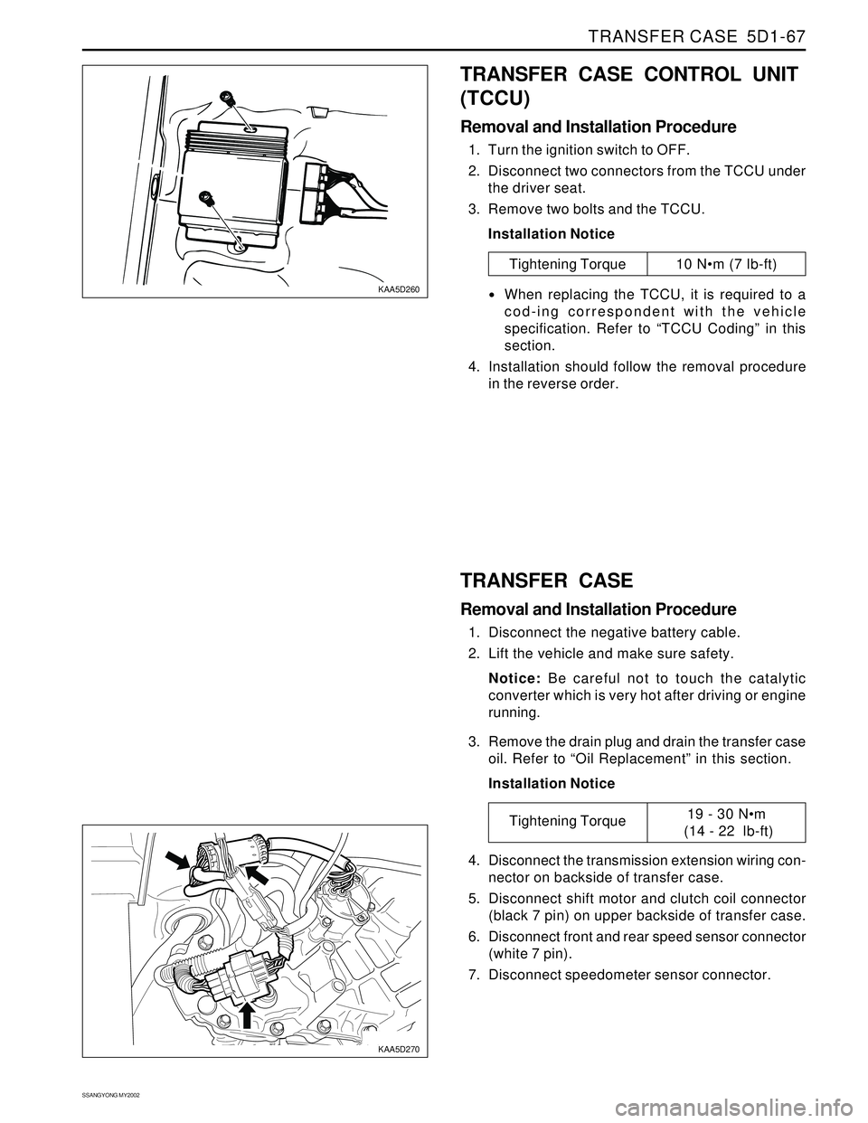
KAA5D260
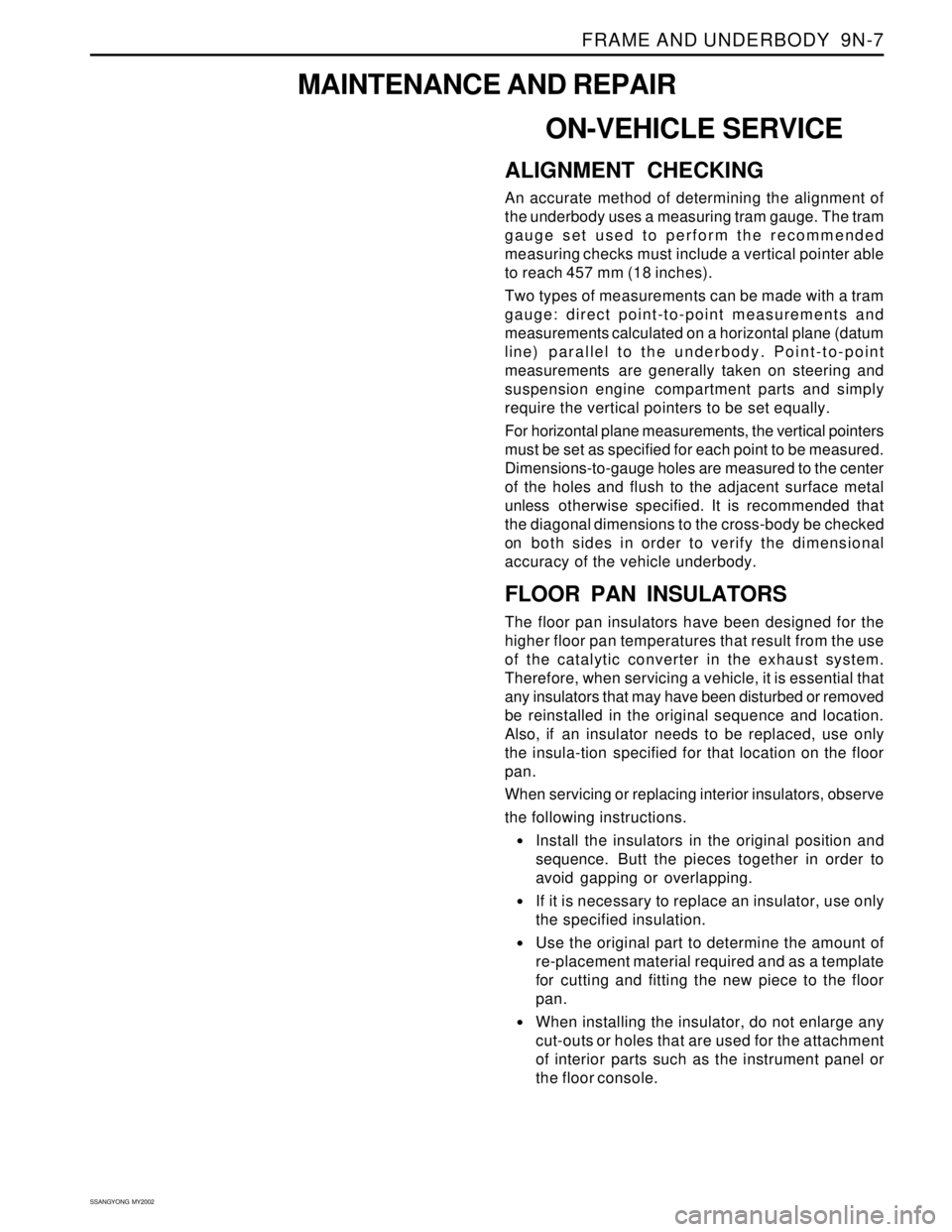
KAA5D270
TRANSFER CASE CONTROL UNIT
(TCCU)
Removal and Installation Procedure
1. Turn the ignition switch to OFF.
2. Disconnect two connectors from the TCCU under
the driver seat.
3. Remove two bolts and the TCCU.
Installation Notice
Tightening Torque 10 Nm (7 lb-ft)
When replacing the TCCU, it is required to a
cod-ing correspondent with the vehicle
specification. Refer to “TCCU Coding” in this
section.
4. Installation should follow the removal procedure
in the reverse order.
TRANSFER CASE
Removal and Installation Procedure
1. Disconnect the negative battery cable.
2. Lift the vehicle and make sure safety.
Notice: Be careful not to touch the catalytic
converter which is very hot after driving or engine
running.
3. Remove the drain plug and drain the transfer case
oil. Refer to “Oil Replacement” in this section.
Installation Notice
4. Disconnect the transmission extension wiring con-
nector on backside of transfer case.
5. Disconnect shift motor and clutch coil connector
(black 7 pin) on upper backside of transfer case.
6. Disconnect front and rear speed sensor connector
(white 7 pin).
7. Disconnect speedometer sensor connector.
Tightening Torque19 - 30 Nm
(14 - 22 lb-ft)
Page 1809 of 2053

FRAME AND UNDERBODY 9N-7
SSANGYONG MY2002
ON-VEHICLE SERVICE
ALIGNMENT CHECKING
An accurate method of determining the alignment of
the underbody uses a measuring tram gauge. The tram
gauge set used to perform the recommended
measuring checks must include a vertical pointer able
to reach 457 mm (18 inches).
Two types of measurements can be made with a tram
gauge: direct point-to-point measurements and
measurements calculated on a horizontal plane (datum
line) parallel to the underbody. Point-to-point
measurements are generally taken on steering and
suspension engine compartment parts and simply
require the vertical pointers to be set equally.
For horizontal plane measurements, the vertical pointers
must be set as specified for each point to be measured.
Dimensions-to-gauge holes are measured to the center
of the holes and flush to the adjacent surface metal
unless otherwise specified. It is recommended that
the diagonal dimensions to the cross-body be checked
on both sides in order to verify the dimensional
accuracy of the vehicle underbody.
FLOOR PAN INSULATORS
The floor pan insulators have been designed for the
higher floor pan temperatures that result from the use
of the catalytic converter in the exhaust system.
Therefore, when servicing a vehicle, it is essential that
any insulators that may have been disturbed or removed
be reinstalled in the original sequence and location.
Also, if an insulator needs to be replaced, use only
the insula-tion specified for that location on the floor
pan.
When servicing or replacing interior insulators, observe
the following instructions.
•Install the insulators in the original position and
sequence. Butt the pieces together in order to
avoid gapping or overlapping.
If it is necessary to replace an insulator, use only
the specified insulation.
Use the original part to determine the amount of
re-placement material required and as a template
for cutting and fitting the new piece to the floor
pan.
When installing the insulator, do not enlarge any
cut-outs or holes that are used for the attachment
of interior parts such as the instrument panel or
the floor console.
MAINTENANCE AND REPAIR
Page 1810 of 2053

SSANGYONG MY2002
9N-8 FRAME AND UNDERBODY
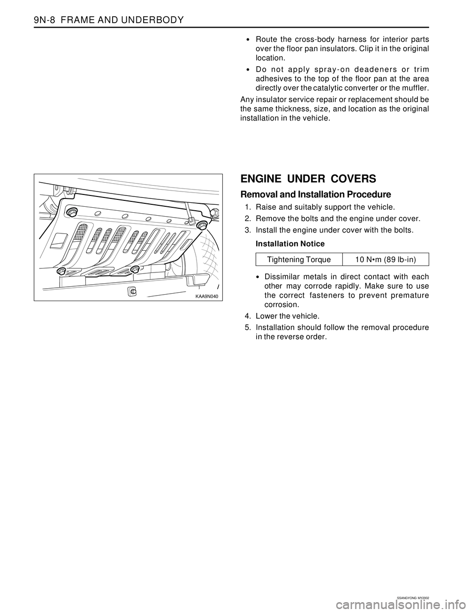
KAA9N040
Route the cross-body harness for interior parts
over the floor pan insulators. Clip it in the original
location.
Do not apply spray-on deadeners or trim
adhesives to the top of the floor pan at the area
directly over the catalytic converter or the muffler.
Any insulator service repair or replacement should be
the same thickness, size, and location as the original
installation in the vehicle.
ENGINE UNDER COVERS
Removal and Installation Procedure
1. Raise and suitably support the vehicle.
2. Remove the bolts and the engine under cover.
3. Install the engine under cover with the bolts.
Installation Notice
Dissimilar metals in direct contact with each
other may corrode rapidly. Make sure to use
the correct fasteners to prevent premature
corrosion.
4. Lower the vehicle.
5. Installation should follow the removal procedure
in the reverse order.
Tightening Torque 10 Nm (89 lb-in)