1997 SSANGYONG KORANDO FUEL PUMP RELAY
[x] Cancel search: FUEL PUMP RELAYPage 458 of 2053

1F2 -- 40 M161 ENGINE CONTROLS
D AEW OO M Y_2000
FUEL SYSTEM
The function of the fuel metering system is to deliver the correct amount of fuel to the engine under all operating condi-
tions. The fuel is delivered to the engine by the individual fuel injectors mounted into the intake manifold near each
cylinder.
The main fuel control sensors are the Mass Air Flow (MAF) sensor and the oxygen (O2) sensors.
The MAF sensor monitors the mass flow of the air being drawn into the engine. An electrically heated element is
mounted in the intake air stream, where it is cooled by the flow of incoming air. Engine Control Module (ECM) modu-
lates the flow of heating current to maintain the temperature differential between the heated film and the intake air at a
constant level. The amount of heating current required to maintain the temperature thus provides an index for the
mass air flow. This concept automatically compensates for variations in air density, as this is one of the factors that
determines the amount of warmth that the surrounding air absorbs from the heated element. MAF sensor is located
between the air filter and the throttle valve.
Under high fuel demands, the MAF sensor reads a high mass flow condition, such as wide open throttle. The ECM
uses this information to enrich the mixture, thus increasing the fuel injector on-- time, to provide the correct amount of
fuel. When decelerating, the mass flow decreases. This mass flow change is sensed by the MAF sensor and read by
the ECM, which then decreases the fuel injector on-- time due to the low fuel demand conditions.
The O2 sensors are located in the exhaust pipe before catalytic converter. The O2 sensors indicate to the ECM the
amount of oxygen in the exhaust gas, and the ECM changes the air/fuel ratio to the engine by controlling the fuel
injectors. The best air/fuel ratio to minimize exhaust emissions is 14.7 to 1, which allows the catalytic converter to
operate most efficiently. Because of the constant measuring and adjusting of the air/fuel ratio, the fuel injection system
is called a “closed loop” system.
The ECM uses voltage inputs from several sensors to determine how much fuel to provide to the engine. The fuel is
delivered under one of several conditions, called ‘‘modes”.
Starting Mode
When the ignition is turned ON, the ECM turns the fuel pump relay on for 1 second. The fuel pump then builds fuel
pressure. The ECM also checks the Engine Coolant Temperature (ECT) sensor and the Throttle Position (TP) sensor
and determines the proper air/fuel ratio for starting the engine. This ranges from 1.5 to 1 at -- 36°C(--33°F) coolant
temperature to 14.7 to 1 at 94°C (201°F) coolant temperature. The ECM controls the amount of fuel delivered in the
starting mode by changing how long the fuel injector is turned on and off. This is done by ‘‘pulsing” the fuel injectors for
very short times.
Run Mode
The run mode has two conditions called ‘‘open loop” and ‘‘closed loop”.
Open Loop
When the engine is first started and it is above 690 rpm, thesystem goes into “open loop” operation. In “open loop”, the
ECM ignores the signal from the HO2S and calculates the air/fuel ratio based on inputs from the ECT sensor and the
MAF sensor. The ECM stays in “open loop” until the following conditions are met:
DThe O2 has a varying voltage output, showing that it is hot enough to operate properly.
DThe ECT sensor is above a specified temperature (22.5°C).
DA specific amount of time has elapsed after starting the engine.
Closed Loop
The specific values for the above conditions vary with different engines and are stored in the Electronically Erasable
Programmable Read -- Only Memory (EEPROM). When these conditions are met, thesystem goes into “closed loop”
operation. In “closed loop”, the ECM calculates the air/fuel ratio (fuel injector on-- time) based on the signals from the
O2 sensors. This allows the air/fuel ratio to stay very close to 14.7 to 1.
Acceleration Mode
The ECM responds to rapid changes in throttle position and airflow and provides extra fuel.
Deceleration Mode
The ECM responds to changes in throttle position and airflow and reduces the amount of fuel. When deceleration is
very fast, the ECM can cut off fuel completely for short periods of time.
Page 461 of 2053

M161 ENGINE CONTROLS 1F2 -- 43
D AEW OO M Y_2000
KAB1F210
Failure
CodeDescriptionTrouble AreaMaintenance Hint
34Fuel pump relay short
circuit to batteryWhen short circuit to power
sourceDInspection the Engine Control Module
(ECM) pin 33 about short circuit or
openwithbadcontact
35Fuel pump relay short
circuit to ground or openWhen short circuit to ground
or open
openwithbadcontact
DInspection the fuel pump relay
DInspection the ECM
Circuit Description
When the ignition switch is turned ON, the ECM will activate the pump relay and run the in -- tank fuel pump. The fuel
pump willoperate as long as the engine is cranking or running and the ECM is receiving ignition reference pulses.
If there are no reference pulses, the ECM will shut off the fuel pump within 2 seconds after the ignition switch is turned
ON, engine stopped or engine stalled.
Fuel Pump Relay Inspection
Measure the voltage between the ECM terminal No. 33 and Ground.
Ignition Switch : ON
0v(for1~2sec.)
Cranking0v
Page 462 of 2053

1F2 -- 44 M161 ENGINE CONTROLS
D AEW OO M Y_2000
Measure the Fuel Delivery from the Fuel Pump
1. Disconnect the return pipe from fuel distributor and insert the appropriate hose into it.
2. Place the hose end into the beaker with the minimum capacity of 1 Liter
3. Turn the ignition switch to “ON” position.
4. Connect the terminal No. 33 and No. 5 of ECM with a service wire.
5. Measure the fuel delivery from the fuel pump
Specified Value
1 Liter/max. 35 sec.
Notice:Check the fuel filter and fuel line when the fuel delivery is not within specified value.
Measure the Current Consumption of Fuel Pump
1. Remove the fuel pump relay from fuse and relay box in trunk, and turn the ignition switch to “ON” position.
2. Using a multimeter, measure the current consumption by connecting the terminal No. 30 and No. 87 of the fuel
pump relay connector.
Specified Value
5~9A
Notice:Replace the fuel pump relay if the measured value is over 9 A.
Page 504 of 2053

1F2 -- 86 M161 ENGINE CONTROLS
D AEW OO M Y_2000
ENGINE CONTROL MODULE
YAA1F830
The Engine Control Module (ECM), located inside the right side kick panel, is the control center of the fuel injection
system. It constantly looks at the information from various sensors and controls the systems that affect the vehicle’s
performance. Engine rpm and air mass are used to measure the air intake quantity resulting in fuel injection metering.
The ECM also performs the diagnostic functions of the system. It can recognize operational problems, store failure
code(s) which identify the problem areas to aid the technician in making repairs.
There are no serviceable parts in the ECM. The calibrations are stored in the ECM in the Programmable Read Only
Memory (PROM).
The ECM supplies either 5 or 12 volts to power the sensors or switches. This is done through resistance in the ECM
which are so high in value that a test light will not come ON when connected to the circuit. In some cases, even an
ordinary shop voltmeter will not give and accurate reading because its resistance is too low. You must use a digital
voltmeter with a 10 Mohm input impedance to get accurate voltage readings. The ECM controls output circuits such as
the ignition coils, the fuel injectors, the fuel pump relay, the camshaft actuator, the canister purge valve, etc., by con-
trolling the ground circuit.
Page 565 of 2053

1B3 -- 16 OM600 ENGINE MECHANICAL
D AEW OO M Y_2000
16. Remove the power steering pump lines.
Notice
Completely drain the fluid.
17. Disconnect the fuel feed line with prefilter from the
feed pump on injection pump.
18. Vehicle with automatic transmission.
Remove the hydraulic lines (19, 20) from oil cooler
(2).
19. Disconnect the engine harness.
20. Disconnect the preheating time relay cable.
Page 1894 of 2053

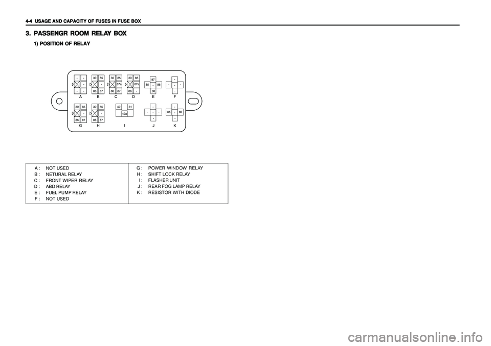
4-4 4-4 4-4 4-4
4-4
USAGE AND CAPACITY OF FUSES IN FUSE BOX USAGE AND CAPACITY OF FUSES IN FUSE BOXUSAGE AND CAPACITY OF FUSES IN FUSE BOX USAGE AND CAPACITY OF FUSES IN FUSE BOX
USAGE AND CAPACITY OF FUSES IN FUSE BOX3. 3.3. 3.
3.
PASSENGR R PASSENGR RPASSENGR R PASSENGR R
PASSENGR R
OOM RELA OOM RELAOOM RELA OOM RELA
OOM RELA
Y BO Y BOY BO Y BO
Y BO
X XX X
X
1) POSITION OF RELAY 1) POSITION OF RELAY1) POSITION OF RELAY 1) POSITION OF RELAY
1) POSITION OF RELAYA : NOT USED
B : NETURAL RELAY
C : FRONT WIPER RELAY
D : ABD RELAY
E : FUEL PUMP RELAY
F : NOT USEDG : POWER WINDOW RELAY
H : SHIFT LOCK RELAY
I : FLASHER UNIT
J : REAR FOG LAMP RELAY
K : RESISTOR WITH DIODE
Page 1896 of 2053

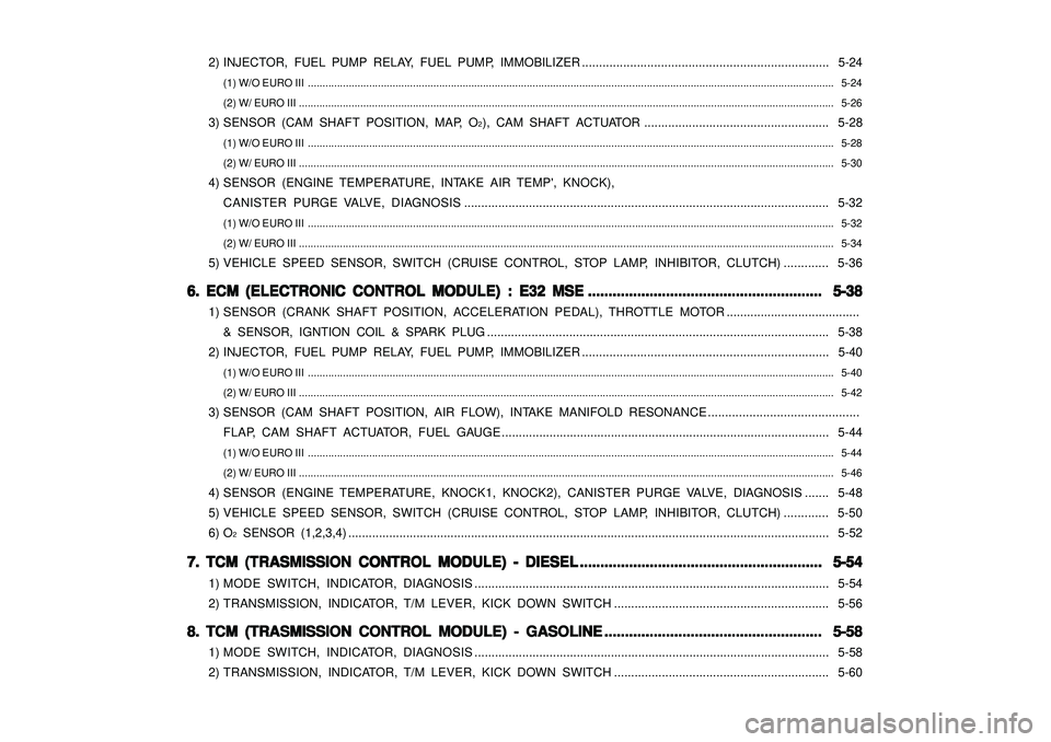
2) INJECTOR, FUEL PUMP RELAY, FUEL PUMP, IMMOBILIZER ........................................................................ 5-24
(1) W/O EURO III .................................................................................................................................................................................... 5-24
(2) W/ EURO III ....................................................................................................................................................................................... 5-26
3) SENSOR (CAM SHAFT POSITION, MAP, O
2), CAM SHAFT ACTUATOR ...................................................... 5-28
(1) W/O EURO III .................................................................................................................................................................................... 5-28
(2) W/ EURO III ....................................................................................................................................................................................... 5-30
4) SENSOR (ENGINE TEMPERATURE, INTAKE AIR TEMP', KNOCK),
CANISTER PURGE VALVE, DIAGNOSIS........................................................................................................... 5-32
(1) W/O EURO III .................................................................................................................................................................................... 5-32
(2) W/ EURO III ....................................................................................................................................................................................... 5-34
5) VEHICLE SPEED SENSOR, SWITCH (CRUISE CONTROL, STOP LAMP, INHIBITOR, CLUTCH) ............. 5-36
6. 6. 6. 6.
6.
ECM (ELECTRONIC CONTROL MODULE) : E32 MSE ECM (ELECTRONIC CONTROL MODULE) : E32 MSEECM (ELECTRONIC CONTROL MODULE) : E32 MSE ECM (ELECTRONIC CONTROL MODULE) : E32 MSE
ECM (ELECTRONIC CONTROL MODULE) : E32 MSE
......................................................... .................................................................................................................. .........................................................
.........................................................
5-38 5-38 5-38 5-38
5-38
1) SENSOR (CRANK SHAFT POSITION, ACCELERATION PEDAL), THROTTLE MOTOR.......................................
& SENSOR, IGNTION COIL & SPARK PLUG .................................................................................................... 5-38
2) INJECTOR, FUEL PUMP RELAY, FUEL PUMP, IMMOBILIZER ........................................................................ 5-40
(1) W/O EURO III .................................................................................................................................................................................... 5-40
(2) W/ EURO III ....................................................................................................................................................................................... 5-42
3) SENSOR (CAM SHAFT POSITION, AIR FLOW), INTAKE MANIFOLD RESONANCE ............................................
FLAP, CAM SHAFT ACTUATOR, FUEL GAUGE................................................................................................ 5-44
(1) W/O EURO III .................................................................................................................................................................................... 5-44
(2) W/ EURO III ....................................................................................................................................................................................... 5-46
4) SENSOR (ENGINE TEMPERATURE, KNOCK1, KNOCK2), CANISTER PURGE VALVE, DIAGNOSIS....... 5-48
5) VEHICLE SPEED SENSOR, SWITCH (CRUISE CONTROL, STOP LAMP, INHIBITOR, CLUTCH) ............. 5-50
6) O
2 SENSOR (1,2,3,4) ............................................................................................................................................. 5-52
7. 7. 7. 7.
7.
TCM (TRASMISSION CONTROL MODULE) - DIESEL TCM (TRASMISSION CONTROL MODULE) - DIESELTCM (TRASMISSION CONTROL MODULE) - DIESEL TCM (TRASMISSION CONTROL MODULE) - DIESEL
TCM (TRASMISSION CONTROL MODULE) - DIESEL
........................................................... ...................................................................................................................... ...........................................................
...........................................................
5-54 5-54 5-54 5-54
5-54
1) MODE SWITCH, INDICATOR, DIAGNOSIS........................................................................................................ 5-54
2) TRANSMISSION, INDICATOR, T/M LEVER, KICK DOWN SWITCH............................................................... 5-56
8. 8. 8. 8.
8.
TCM (TRASMISSION CONTROL MODULE) - GASOLINE TCM (TRASMISSION CONTROL MODULE) - GASOLINETCM (TRASMISSION CONTROL MODULE) - GASOLINE TCM (TRASMISSION CONTROL MODULE) - GASOLINE
TCM (TRASMISSION CONTROL MODULE) - GASOLINE
..................................................... .......................................................................................................... .....................................................
.....................................................
5-58 5-58 5-58 5-58
5-58
1) MODE SWITCH, INDICATOR, DIAGNOSIS........................................................................................................ 5-58
2) TRANSMISSION, INDICATOR, T/M LEVER, KICK DOWN SWITCH............................................................... 5-60
Page 1918 of 2053

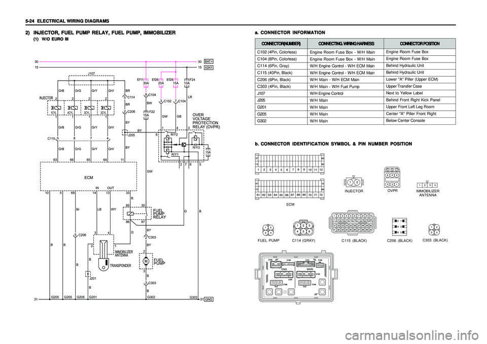
5-24 5-24 5-24 5-24
5-24
ELECTRICAL WIRING DIAGRAMS ELECTRICAL WIRING DIAGRAMSELECTRICAL WIRING DIAGRAMS ELECTRICAL WIRING DIAGRAMS
ELECTRICAL WIRING DIAGRAMS2) 2)2) 2)
2)
INJECTOR, FUEL PUMP RELAY, FUEL PUMP, IMMOBILIZER INJECTOR, FUEL PUMP RELAY, FUEL PUMP, IMMOBILIZERINJECTOR, FUEL PUMP RELAY, FUEL PUMP, IMMOBILIZER INJECTOR, FUEL PUMP RELAY, FUEL PUMP, IMMOBILIZER
INJECTOR, FUEL PUMP RELAY, FUEL PUMP, IMMOBILIZER
(1) W/O EURO III (1) W/O EURO III(1) W/O EURO III (1) W/O EURO III
(1) W/O EURO III
b. b.b. b.
b.
CONNECTOR IDENTIFICATION SYMBOL & PIN NUMBER POSITION CONNECTOR IDENTIFICATION SYMBOL & PIN NUMBER POSITIONCONNECTOR IDENTIFICATION SYMBOL & PIN NUMBER POSITION CONNECTOR IDENTIFICATION SYMBOL & PIN NUMBER POSITION
CONNECTOR IDENTIFICATION SYMBOL & PIN NUMBER POSITION
IMMOBILIZER
ANTENNA
ECM
OVPR
INJECTOR
a. a.a. a.
a.
CONNECTOR INFORMATION CONNECTOR INFORMATIONCONNECTOR INFORMATION CONNECTOR INFORMATION
CONNECTOR INFORMATION
C114 (GRAY) FUEL PUMP
C206 (BLACK)
C115 (BLACK)
C303 (BLACK)
C102 (4Pin, Colorless)
C104 (8Pin, Colorless)
C114 (6Pin, Gray)
C115 (40Pin, Black)
C206 (6Pin, Black)
C303 (4Pin, Black)
J107
J205
G201
G205
G302CONNECTOR(NUMBER) CONNECTOR(NUMBER)CONNECTOR(NUMBER) CONNECTOR(NUMBER)
CONNECTOR(NUMBER)
CONNECTING. WIRING HARNESS CONNECTING. WIRING HARNESSCONNECTING. WIRING HARNESS CONNECTING. WIRING HARNESS
CONNECTING. WIRING HARNESS
CONNECTOR POSITION CONNECTOR POSITIONCONNECTOR POSITION CONNECTOR POSITION
CONNECTOR POSITION
Engine Room Fuse Box - W/H Main
Engine Room Fuse Box - W/H Main
W/H Engine Control - W/H ECM Main
W/H Engine Control - W/H ECM Main
W/H Main - W/H ECM Main
W/H Main - W/H Fuel Pump
W/H Engine Control
W/H Main
W/H Main
W/H Main
W/H MainEngine Room Fuse Box
Engine Room Fuse Box
Behind Hydraulic Unit
Behind Hydraulic Unit
Lower "A" Piller (Upper ECM)
Upper Transfer Case
Next to Yellow Label
Behind Front Right Kick Panel
Upper Front Left Leg Room
Center "A" Piller Front Right
Below Center Console