1997 SSANGYONG KORANDO light
[x] Cancel search: lightPage 1780 of 2053
SSANGYONG MY2002
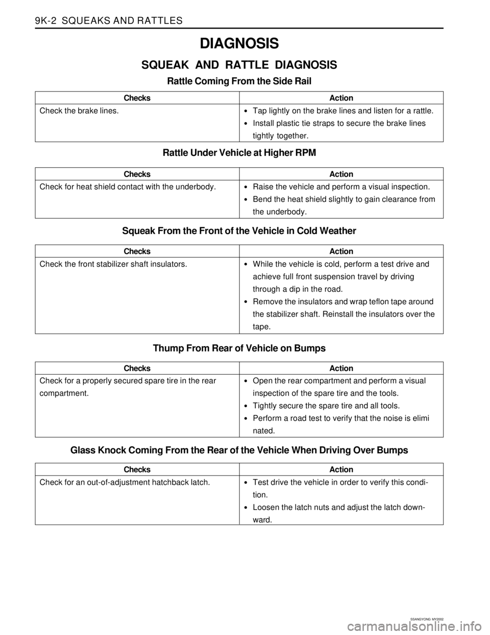
9K-2 SQUEAKS AND RATTLES
•Tap lightly on the brake lines and listen for a rattle.
Install plastic tie straps to secure the brake lines
tightly together.
Raise the vehicle and perform a visual inspection.
Bend the heat shield slightly to gain clearance from
the underbody.
While the vehicle is cold, perform a test drive and
achieve full front suspension travel by driving
through a dip in the road.
Remove the insulators and wrap teflon tape around
the stabilizer shaft. Reinstall the insulators over the
tape.
Open the rear compartment and perform a visual
inspection of the spare tire and the tools.
Tightly secure the spare tire and all tools.
Perform a road test to verify that the noise is elimi
nated.
DIAGNOSIS
SQUEAK AND RATTLE DIAGNOSIS
Rattle Coming From the Side Rail
Check the brake lines.ChecksAction
Rattle Under Vehicle at Higher RPM
Squeak From the Front of the Vehicle in Cold Weather
Check the front stabilizer shaft insulators.ChecksAction
Check for heat shield contact with the underbody.ChecksAction
Thump From Rear of Vehicle on Bumps
Check for a properly secured spare tire in the rear
compartment.ChecksAction
Glass Knock Coming From the Rear of the Vehicle When Driving Over Bumps
Check for an out-of-adjustment hatchback latch.ChecksActionTest drive the vehicle in order to verify this condi-
tion.
Loosen the latch nuts and adjust the latch down-
ward.
Page 1781 of 2053

SQUEAKS AND RATTLES 9K-3
SSANGYONG MY2002
Check for a lack of lubrication of the door hinge pins.ChecksActionOperate the doors and listen for squeaks.
Lubricate the door hinge pins with light oil and coat
with lithium grease.
Squeak Coming From Console When Shifting Manual Transaxle
(Condition Occurs In Cold Weather with a Cold Engine)
Check the manual transaxle control lever lower boot.ChecksActionMove the control lever between gears and listen for
squeaks.
Remove the floor console and replace the lower shift
boot or apply talcum powder to the lower shift boot.
Squeak When Operating Doors
Check for vibration of the fuse box cover against the
instrument panel side trim.ChecksActionTap on thecoverwith a fingerandlisten fora buzz.
Apply 6.35 mm (0.250 inch) by 25.4 mm (1.00 inch)
felt pads to the side trim where the cover makes
contact.
Squeak Coming From Instrument Cluster Trim Plate
Check for rubbing of the cluster trim plate on the
instrument panel.ChecksActionTest drive the vehicle in order to verify this condi-
tion.
Remove the instrument cluster trim plate and install
felt tape to the edges.
Buzz From the Left Side of Instrument Panel
Check the door lock solenoid.
Check for rattling electrical connectors inside the door
trim panel.ChecksActionRemove the door trim panel and check if the sole-
noid is loose.
Tighten the solenoid bolts.
Tap on the trim panel and listen for a rattle.
Remove the trim panel and wrap foam padding
around the connectors as required.
Rattle Coming From Door
Page 1800 of 2053
EXTERIOR TRIM 9M-5
SSANGYONG MY2002
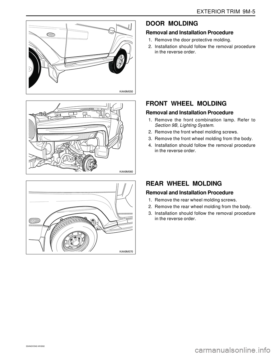
KAA9M050
KAA9M060
FRONT WHEEL MOLDING
Removal and Installation Procedure
1. Remove the front combination lamp. Refer to
Section 9B, Lighting System.
2. Remove the front wheel molding screws.
3. Remove the front wheel molding from the body.
4. Installation should follow the removal procedure
in the reverse order.
DOOR MOLDING
Removal and Installation Procedure
1. Remove the door protective molding.
2. Installation should follow the removal procedure
in the reverse order.
REAR WHEEL MOLDING
Removal and Installation Procedure
1. Remove the rear wheel molding screws.
2. Remove the rear wheel molding from the body.
3. Installation should follow the removal procedure
in the reverse order.
KAA9M070
Page 1823 of 2053
SSANGYONG MY2002
9P-6 DOORS
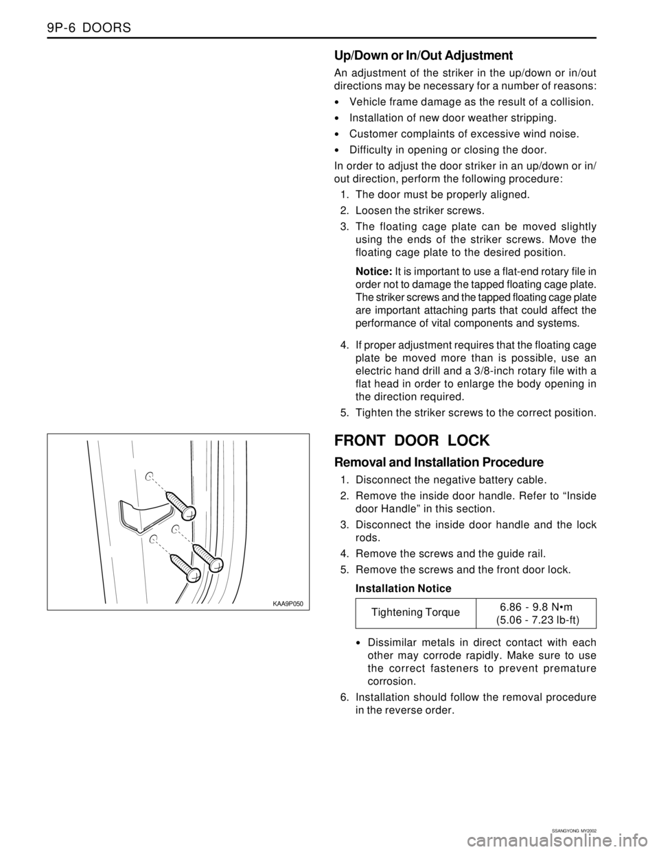
KAA9P050
FRONT DOOR LOCK
Removal and Installation Procedure
1. Disconnect the negative battery cable.
2. Remove the inside door handle. Refer to “Inside
door Handle” in this section.
3. Disconnect the inside door handle and the lock
rods.
4. Remove the screws and the guide rail.
5. Remove the screws and the front door lock.
Installation Notice
Dissimilar metals in direct contact with each
other may corrode rapidly. Make sure to use
the correct fasteners to prevent premature
corrosion.
6. Installation should follow the removal procedure
in the reverse order.
Up/Down or In/Out Adjustment
An adjustment of the striker in the up/down or in/out
directions may be necessary for a number of reasons:
Vehicle frame damage as the result of a collision.
Installation of new door weather stripping.
Customer complaints of excessive wind noise.
Difficulty in opening or closing the door.
In order to adjust the door striker in an up/down or in/
out direction, perform the following procedure:
1. The door must be properly aligned.
2. Loosen the striker screws.
3. The floating cage plate can be moved slightly
using the ends of the striker screws. Move the
floating cage plate to the desired position.
Notice: It is important to use a flat-end rotary file in
order not to damage the tapped floating cage plate.
The striker screws and the tapped floating cage plate
are important attaching parts that could affect the
performance of vital components and systems.
4. If proper adjustment requires that the floating cage
plate be moved more than is possible, use an
electric hand drill and a 3/8-inch rotary file with a
flat head in order to enlarge the body opening in
the direction required.
5. Tighten the striker screws to the correct position.
Tightening Torque6.86 - 9.8 Nm
(5.06 - 7.23 lb-ft)
Page 1835 of 2053
SSANGYONG MY2002
9Q-4 ROOF
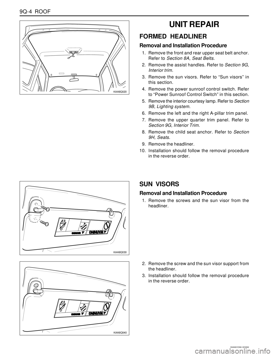
KAA9Q030
SUN VISORS
Removal and Installation Procedure
1. Remove the screws and the sun visor from the
headliner.
KAA9Q020
UNIT REPAIR
FORMED HEADLINER
Removal and Installation Procedure
1. Remove the front and rear upper seat belt anchor.
Refer to Section 8A, Seat Belts.
2. Remove the assist handles. Refer to Section 9G,
Interior trim.
3. Remove the sun visors. Refer to “Sun visors” in
this section.
4. Remove the power sunroof control switch. Refer
to “Power Sunroof Control Switch” in this section.
5. Remove the interior courtesy lamp. Refer to Section
9B, Lighting system.
6. Remove the left and the right A-pillar trim panel.
7. Remove the upper quarter trim panel. Refer to
Section 9G, Interior Trim.
8. Remove the child seat anchor. Refer to Section
9H, Seats.
9. Remove the headliner.
10. Installation should follow the removal procedure
in the reverse order.
2. Remove the screw and the sun visor support from
the headliner.
3. Installation should follow the removal procedure
in the reverse order.
KAA9Q040
Page 1843 of 2053
SECTION 9S
BODY REAR END
CAUTION: Disconnect the negative battery cable before removing or installing any electrical unit or when a
tool or equipment could easily come in contact with exposed electrical terminals. Disconnecting this cable
will help prevent personal injury and damage to the vehicle. The ignition must also be in LOCK unless
otherwise noted.
TABLE OF CONTENTS
Description and Operation...................................9S-2
Fuel Filler Door.....................................................9S-2
Components Locator............................................9S-3
Lighting System..................................................9S-3
Repair Instructions................................................9S-4On-Vehicle Service Unit Repair................................9S-4
Fuel Filler Door.....................................................9S-4
Fuel Filler Door Remote Handle and Cable............9S-4
Specifications.......................................................9S-5
Fastener Tightening Specifications.......................9S-5
Page 1845 of 2053
BODY REAR END 9S-3
SSANGYONG MY2002
COMPONENTS LOCATOR
LIGHTING SYSTEM
KAA9S010
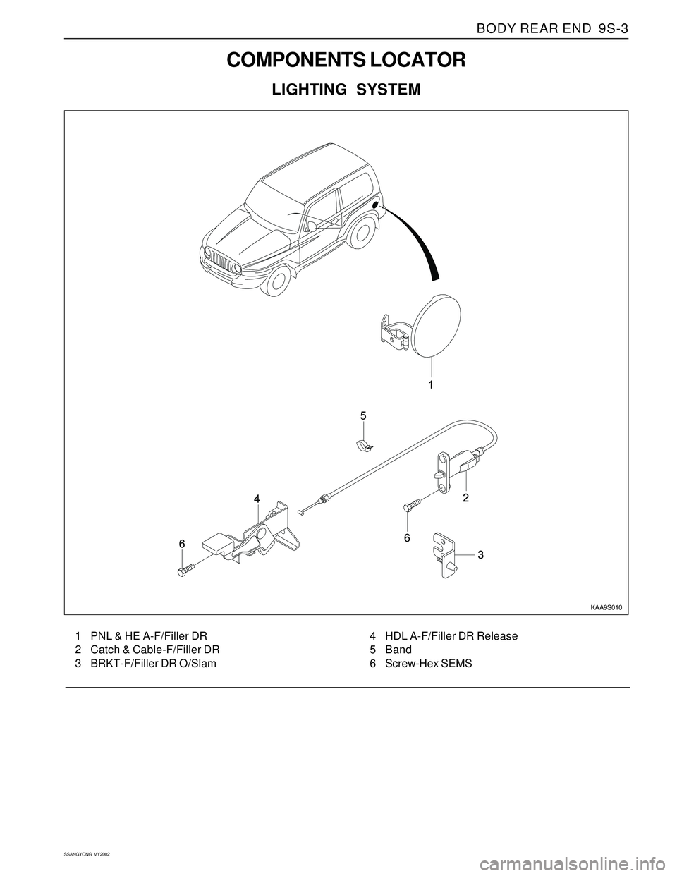
1 PNL & HE A-F/Filler DR
2 Catch & Cable-F/Filler DR
3 BRKT-F/Filler DR O/Slam4 HDL A-F/Filler DR Release
5 Band
6 Screw-Hex SEMS
Page 1849 of 2053
SSANGYONG MY2002
9T1-2 REMOTE KEYLESS ENTRY AND ANTI-THEFT SYSTEM
DESCRIPTION AND OPERATION
REMOTE KEYLESS ENTRY AND
ANTI-THEFT SYSTEM
The remote keyless entry and anti-theft system can
perform the following functions:
•Remotely lock and unlock the vehicle doors by
means of a hand-held, high-frequency transmitter.
Sense intrusion into the vehicle through the doors
or the hood.
Activate a warning if an intrusion is detected.
Automatically relock the doors if thedoor or the
tail gate is not opened within 30 seconds after the
vehicle has been unlocked by remote keyless
entry.
Help the driver find the vehicle in a parking area.
The remote keyless entry system consist of the
following components:
STICS.
Remote keyless entry system receiver.
Hand-held transmitter.
Tailgate open switch.
Door contact switch.
Siren.
Hood open switch
Key reminder switch.
Antenna.
STICS can perform the following functions:
1. Wiper INT sening vehicle speed.
By operating INT tiem control volume, variable
time will be changed within 1.5-20 seconds
2. Washer relating wiper.
3. Dimming room lamp.
When room lamp is coupled with door, it truns on
if door is opened. After closing the door it
maintains 2 seconds of lighting and dims off
whithin 3 seconds.
4. Time delayed power window control.
Power window can be operated within 30 seconds
after truning the IGN 1 switch from ON to OFF. If
driver/passenger’s door is opened within the 30
seconds from that moment.
5. Rear defogger timer.
The rear defogger will be operated for 12 min. by
turning ON the defogger switch while engine is
running.
Defogger will be stopped by pushing the switch
again.
The defogger will be operated 6 mim, if push ON
the switch within 10 min. after 12 min. of operation.6. Seat belt waring.
The warning lamp will be turned on for about 6
sec. With an intermittent chime bell when the IGN.
Switch is ON unless fastening the seat belt.
7. parking brake warning.
The indicator lamp will flash if drive while the
parking brake is applied.
8. Tail lamp lighting warning.
When the driver’s door is opened while the tail
lamp is still ON, the buzzer operates intermittently.
In this condition, the door will be automatically
unlock when it locked.
9. Door ajar warning.
The indicator lamp will be blinking when the door
is not closed completely and driving.
10. IGN key reminder.
The chime will be operated intermittently if the
driver’s door is opened while the IGN key is still
remain-ing in the ignition switch. In this condition,
the door will be automatically unlocked when it
locked.
11. Central door lock.
All doors will be locked/unlocked by locking/
unlocking the driver’s or passenger’s door.
12. coupled with REKES.
Being coupled with REKES (remote keyless entry
system), all doors will be locked/unlocked
according to signals of transmitter when the
ignition key is not inserted.
13. iginition key hole illumination.
coupled with door switch, ignition key hole
illumination lamp will trun on when the driver ’s
door is opened and will dim off after 10 sec. After
closing the door.
14. Auto door lock.
All doors will be locked automatically if the vehicle
speed reaches 50 km/h though the doors are in
unlock.
15. Auto door unlock.
All doors will be automatically unlock if the vehicle
crashes while driving (over 15km/h).
Operate the burglar alarm.
1. Burglar alarm must operate immediately when the
door, tailgate or hood is opened with improper
ways after all doors and hood were closed and
continued this status for 1 seconds.
2. If the tailgate is opened by key when the system
is on the burglar alarm cindition, the sysem must
be changed to the second burglar alarm condition
frim normal condition.