1997 SSANGYONG KORANDO Pedal
[x] Cancel search: PedalPage 1374 of 2053
SSANGYONG MY2002
5D1-4 TRANSFER CASE
COMPONENTS OF THE TOD
TRANSFER CASE SYSTEM
Shift Motor
It locates backside transfer case, which drives rotary
helical cam. When mode select switch changes to 4L,
shift fork is on position for 2.48 : 1 by rotation of helical
cam.
Rear Speed Sensor
A hall effect speed sensor which produces a square
wave. 0 to 5 volts direct current signal in response to
a rotating 30-tooth wheel coupled to the rear propeller
shaft inside the transfer case. Each rotation of the rear
propeller shaft will result in 30 speed sensor pulse.
Front Speed Sensor
A hall effect speed sensor which produces a square
wave. 0 to 5 volts direct current signal in response to
a rotating 30-tooth wheel coupled to the front propeller
shaft inside the transfer case. Each rotation of the front
propeller shaft will result in 30 speed sensor pulse.
Electro-Magnetic Clutch
An electromagnetic clutch used to control the amount
of torque applied to the front propeller shaft.
Position Encoder
A set of 4 gray code switches which provide feedback
to the TCCU indicating the position of the shift motor.
Clutch Pedal Position Switch
A switch on vehicles equipped with a manual transmis-
sion which indicates that the clutch pedal is depressed
Park/Neutral Position Switch
A switch on vehicles equipped with an automatic trans-
mission which indicates that the transmission is in neu-
tral.
4H/4L Switch
A switch selects the desired gear ratio.
DEFINITION OF TERMINOLOGY
Shift Inhibit Speed
The vehicle speed limit, which transfer case shifts, is
disallowed. Vehicle speed is indicated by propeller
shaft speed measurement.
Duty Cycle
Duty cycle is the time the electromagnetic clutch is on
divided by the period in which it is being modulated.
Touch-off
A minimum amount of duty cycle applied to the electro
magnetic clutch.
Front Overrun
A condition where the front propeller shaft is turning at
a rate which is faster than the rear propeller shaft.
Rear Overrun
A condition where the rear propeller shaft is turning at
a rate which is faster than the front propeller shaft.
High Range
The highest (numerically lowest = 1 : 1) gear ratio be-
tween the input and outputs of the transfer case.
Low Range
The lowest (numerically highest = 2.48 : 1) gear ratio
between the input and outputs of the transfer case.
OPERATION OF THE TOD
TRANSFER CASE SYSTEM
Initial Operation of TOD Control Unit
When ignition switch is turned to ON, 4WD LOW and
4WD CHECK lamp illuminates for 0.6 second to check
bulb in instrument panel, then perform diagnosis of
system. Refer to “Self-Diagnosis Test” in this section.
Electric Shift System Operation
The electric shift system is responsible for changing
the transfer case gear ratio by controlling the electric
shift motor. The TCCU monitors the 4H/4L switch, park/
neutral position switch, speed sensors, position
encoder, and ignition switch.
A range change is initiated when:
The 4H/4L switch is changed from 4H to 4L or from
4L to 4H.
The motor position (as indicated by the position
encoder) does not match the 4H/4L switch
immediately after the ignition is turned on.
Shift Criteria
When a range change is initiated a diagnostic test will
be completed on the motor, speed sensors, and
position encoder. If the diagnostic test fails, the shift
will not be attempted. If all components are operating
properly, the TCCU will attempt a range change after
the following shift criteria are met:
The transmission is in neutral for 2 seconds after
the shift is requested.
Both propeller shaft speeds are below 87 rpm (2580
pulses/minute). If the transmission is taken out of
neutral before 2 seconds has passed, or either
propeller shaft speed increases above the limit, the
shift will be suspended and the 4L indicator will
continue to blink until the criteria are met again or
the 4H/4L switch is returned to the original position.
Range Change
When the shift criteria are met, the motor is rotated in
the appropriate direction (as determined by the selector
switch) until one of the following occurs:
Page 1402 of 2053
SSANGYONG MY2002
5D2-2 TRANSFER CASE (PART TIME - 4408)
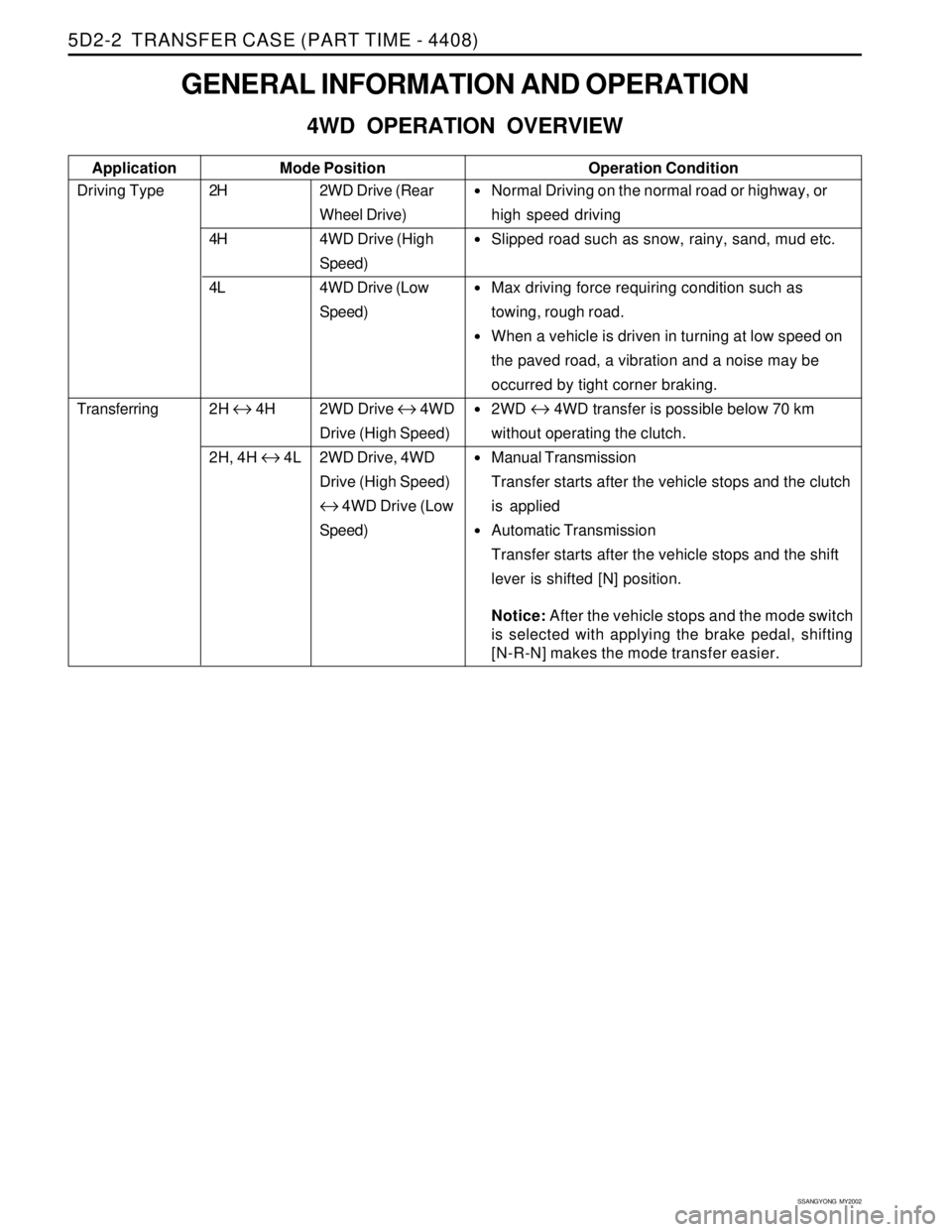
2WD Drive (Rear
Wheel Drive)
4WD Drive (High
Speed)
4WD Drive (Low
Speed)
2WD Drive
↔ 4WD
Drive (High Speed)
2WD Drive, 4WD
Drive (High Speed)
↔ 4WD Drive (Low
Speed)
GENERAL INFORMATION AND OPERATION
4WD OPERATION OVERVIEW
Driving Type
Transferring2H
4H
4L
2H
↔ 4H
2H, 4H
↔ 4L Application
•Normal Driving on the normal road or highway, or
high speed driving
Slipped road such as snow, rainy, sand, mud etc.
Max driving force requiring condition such as
towing, rough road.
When a vehicle is driven in turning at low speed on
the paved road, a vibration and a noise may be
occurred by tight corner braking.
2WD ↔ 4WD transfer is possible below 70 km
without operating the clutch.
Manual Transmission
Transfer starts after the vehicle stops and the clutch
is applied
Automatic Transmission
Transfer starts after the vehicle stops and the shift
lever is shifted [N] position.
Notice: After the vehicle stops and the mode switch
is selected with applying the brake pedal, shifting
[N-R-N] makes the mode transfer easier.
Operation ConditionMode Position
Page 1408 of 2053
SSANGYONG MY2002
5D2-8 TRANSFER CASE (PART TIME - 4408)
KAA5D050
KAA5D060
KAA5D070
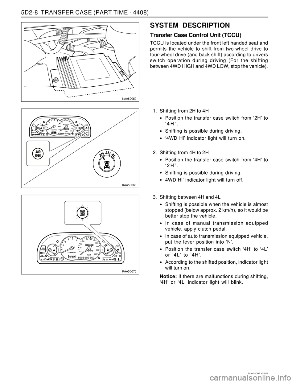
1. Shifting from 2H to 4H
Position the transfer case switch from ‘2H’ to
‘4H’.
Shifting is possible during driving.
‘4WD Hl’ indicator light will turn on.
2. Shifting from 4H to 2H
Position the transfer case switch from ‘4H’ to
‘2H’.
Shifting is possible during driving.
4WD Hl’ indicator light will turn off.
SYSTEM DESCRIPTION
Transfer Case Control Unit (TCCU)
TCCU is located under the front left handed seat and
permits the vehicle to shift from two-wheel drive to
four-wheel drive (and back shift) according to drivers
switch operation during driving (For the shifting
between 4WD HIGH and 4WD LOW, stop the vehicle).
3. Shifting between 4H and 4L
Shifting is possible when the vehicle is almost
stopped (below approx. 2 km/h), so it would be
better stop the vehicle.
In case of manual transmission equipped
vehicle, apply clutch pedal.
In case of auto transmission equipped vehicle,
put the lever position into ‘N’.
Position the transfer case switch ‘4H’ to ‘4L’
or ‘4L’ to ‘4H’.
According to the shifted position, indicator light
will turn on.
Notice: If there are malfunctions during shifting,
‘4H’ or ‘4L’ indicator light will blink.
Page 1420 of 2053
TRANSFER CASE (PART TIME - 4408) 5D2-21
SSANGYONG MY2002
KAA5D240
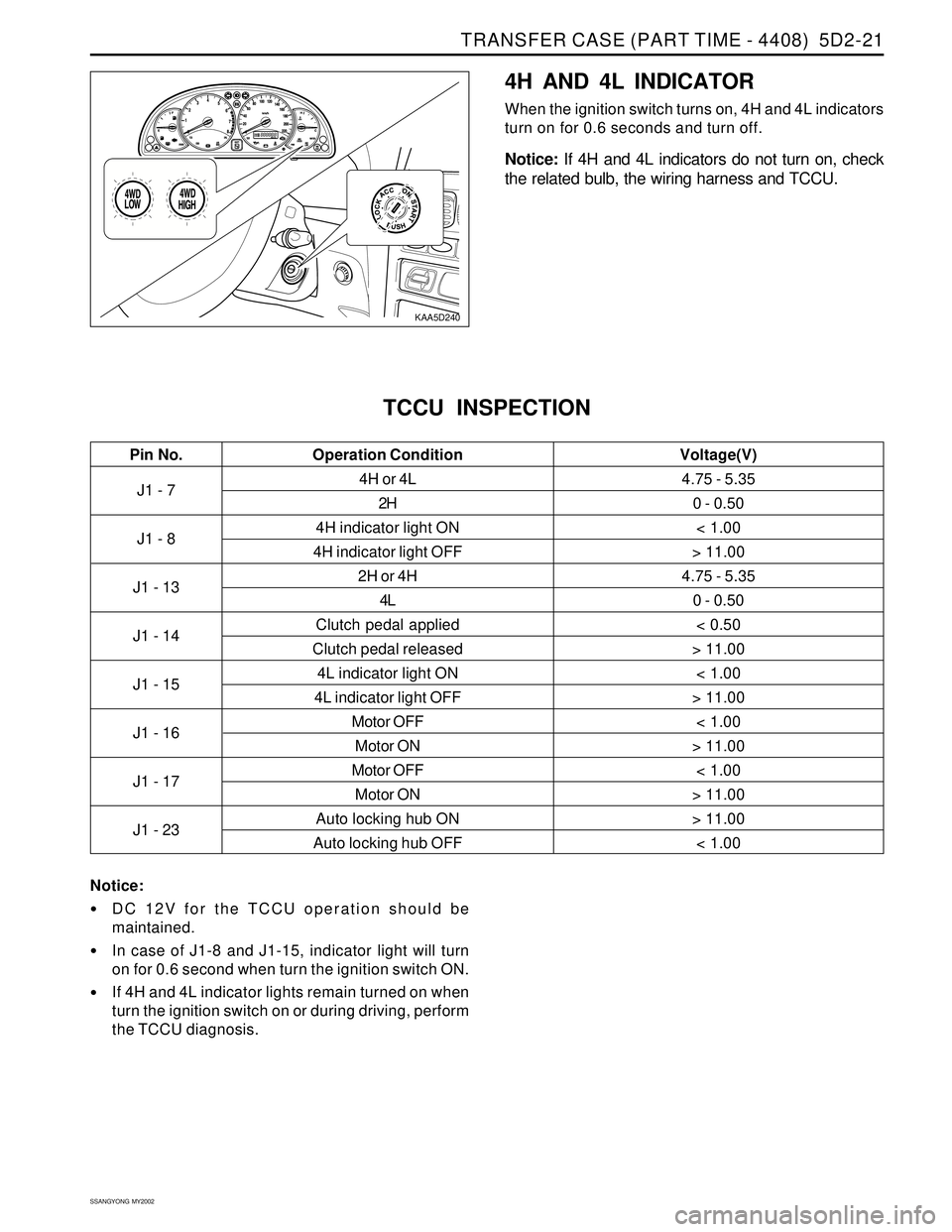
4H AND 4L INDICATOR
When the ignition switch turns on, 4H and 4L indicators
turn on for 0.6 seconds and turn off.
Notice: If 4H and 4L indicators do not turn on, check
the related bulb, the wiring harness and TCCU.
J1 - 7
J1 - 8
J1 - 13
J1 - 14
J1 - 15
J1 - 16
J1 - 17
J1 - 234H or 4L
2H
4H indicator light ON
4H indicator light OFF
2H or 4H
4L
Clutch pedal applied
Clutch pedal released
4L indicator light ON
4L indicator light OFF
Motor OFF
Motor ON
Motor OFF
Motor ON
Auto locking hub ON
Auto locking hub OFF
TCCU INSPECTION
4.75 - 5.35
0 - 0.50
< 1.00
> 11.00
4.75 - 5.35
0 - 0.50
< 0.50
> 11.00
< 1.00
> 11.00
< 1.00
> 11.00
< 1.00
> 11.00
> 11.00
< 1.00
Pin No. Voltage(V)Operation Condition
Notice:
DC 12V for the TCCU operation should be
maintained.
In case of J1-8 and J1-15, indicator light will turn
on for 0.6 second when turn the ignition switch ON.
If 4H and 4L indicator lights remain turned on when
turn the ignition switch on or during driving, perform
the TCCU diagnosis.
Page 1664 of 2053
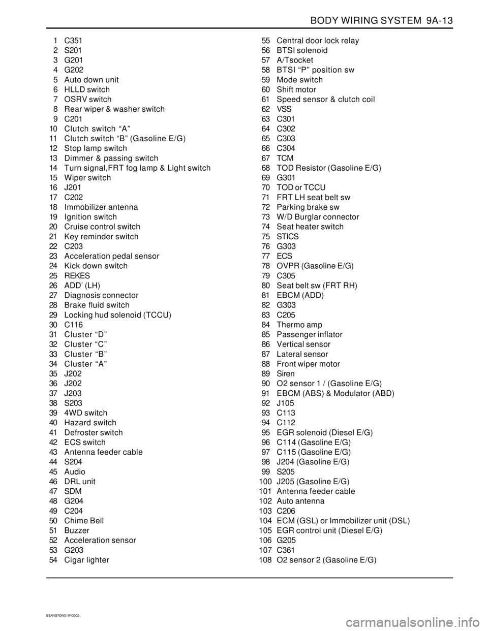
BODY WIRING SYSTEM 9A-13
SSANGYONG MY2002
1 C351
2 S201
3 G201
4 G202
5 Auto down unit
6 HLLD switch
7 OSRV switch
8 Rear wiper & washer switch
9 C201
10 Clutch switch “A”
11 Clutch switch “B” (Gasoline E/G)
12 Stop lamp switch
13 Dimmer & passing switch
14 Turn signal,FRT fog lamp & Light switch
15 Wiper switch
16 J201
17 C202
18 Immobilizer antenna
19 Ignition switch
20 Cruise control switch
21 Key reminder switch
22 C203
23 Acceleration pedal sensor
24 Kick down switch
25 REKES
26 ADD’ (LH)
27 Diagnosis connector
28 Brake fluid switch
29 Locking hud solenoid (TCCU)
30 C116
31 Cluster “D”
32 Cluster “C”
33 Cluster “B”
34 Cluster “A”
35 J202
36 J202
37 J203
38 S203
39 4WD switch
40 Hazard switch
41 Defroster switch
42 ECS switch
43 Antenna feeder cable
44 S204
45 Audio
46 DRL unit
47 SDM
48 G204
49 C204
50 Chime Bell
51 Buzzer
52 Acceleration sensor
53 G203
54 Cigar lighter55 Central door lock relay
56 BTSI solenoid
57 A/Tsocket
58 BTSI “P” position sw
59 Mode switch
60 Shift motor
61 Speed sensor & clutch coil
62 VSS
63 C301
64 C302
65 C303
66 C304
67 TCM
68 TOD Resistor (Gasoline E/G)
69 G301
70 TOD or TCCU
71 FRT LH seat belt sw
72 Parking brake sw
73 W/D Burglar connector
74 Seat heater switch
75 STICS
76 G303
77 ECS
78 OVPR (Gasoline E/G)
79 C305
80 Seat belt sw (FRT RH)
81 EBCM (ADD)
82 G303
83 C205
84 Thermo amp
85 Passenger inflator
86 Vertical sensor
87 Lateral sensor
88 Front wiper motor
89 Siren
90 O2 sensor 1 / (Gasoline E/G)
91 EBCM (ABS) & Modulator (ABD)
92 J105
93 C113
94 C112
95 EGR solenoid (Diesel E/G)
96 C114 (Gasoline E/G)
97 C115 (Gasoline E/G)
98 J204 (Gasoline E/G)
99 S205
100 J205 (Gasoline E/G)
101 Antenna feeder cable
102 Auto antenna
103 C206
104 ECM (GSL) or Immobilizer unit (DSL)
105 EGR control unit (Diesel E/G)
106 G205
107 C361
108 O2 sensor 2 (Gasoline E/G)
Page 1676 of 2053
SSANGYONG MY2002
9B-2 LIGHTING SYSTEM
DESCRIPTION AND OPERATION
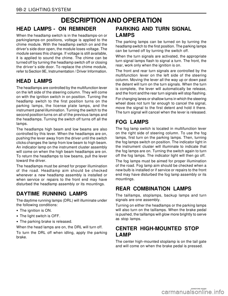
HEAD LAMPS - ON REMINDER
When the headlamp switch is in the headlamps-on or
parkinglamps-on positions, voltage is applied to the
chime module. With the headlamp switch on and the
driver’s side door open, the module loses voltage. The
module senses this change. If voltage is still available,
it is applied to sound the chime. The chime can be
turned off by turning the headlamp switch off or closing
the driver’s side door. To replace the chime module,
refer to Section 9E, Instrumentation / Driver Information.
HEAD LAMPS
The headlamps are controlled by the multifunction lever
on the left side of the steering column. They will come
on with the ignition switch in on position. Turning the
headlamp switch to the first position turns on the
parking lamps, the license plate lamps, and the
instrument panel illumination. Turning the switch to the
second position turns on all of the previous lamps and
the headlamps. Turning the switch off turns off all the
lamps.
The headlamps high beam and low beams are also
controlled by this lever. When the headlamps are on,
pushing the lever away from the driver until the switch
clicks changes the lamp from low beam to high beam.
An indicator lamp on the instrument cluster assembly
will come on when the high beam headlamps are on.
To return the headlamps to low beams, pull the lever
toward the driver.
The headlamps must be aimed for proper illumination
of the road. Headlamp aim should be checked
whenever a new headlamp assembly is installed or
when service or repairs to the front end may have
disturbed the headlamp assembly or its mountings.
DAYTIME RUNNING LAMPS
The daytime running lamps (DRL) will illuminate under
the following conditions:
The ignition is ON.
The light switch is OFF.
The parking brake is released.
When the head lamps are on, the DRL will turn off.
To turn the DRL off when idling, apply the parking
brake.
PARKING AND TURN SIGNAL
LAMPS
The parking lamps can be turned on by turning the
headlamp switch to the first position. The parking lamps
can be turned off by turning the switch off.
When the turn signals are activated, the appropriate
turn signal lamps flash to signal a turn. The front, the
rear, work only when the ignition is on.
The front and rear turn signals are controlled by the
multifunction lever on the left side of the steering
column. Moving the lever all the way up or down past
the detent will turn on the turn signals. When the turn
is complete, the lever will automatically be release,
and the front and the rear turn signals will stop flashing.
For changing lanes or shallow turns in which the steering
wheel does not turn far enough to cancel the signal,
move the signal to the first detent and hold it there.
The turn signal will cancel when the lever is released.
FOG LAMPS
The fog lamp switch is located in multifunction lever
on the right side of steering column. To use the fog
lamps, first turn on the parking lamps. Then, turning
the fog lamps switch on position. The indicator light in
the instrument cluster will illuminate to indicate that
the fog lamps are on. Turning the switch again to turn
off the fog lamps. The indicator light will then go off.
The fog lamps must be aimed for proper illumination
of the road. Fog lamp aim should be checked when a
new bulb is installed or if service or repairs to the front
end may have disturbed the fog lamp assembly or its
mountings.
REAR COMBINATION LAMPS
The taillamps, stoplamps, backup lamps and turn
signals are one assembly.
Turning on either the headlamps or the parking lamps
will also turn on the taillamps. When the brake pedal
is pushed, the taillamps will glow more brightly to serve
as stop lamps.
CENTER HIGH-MOUNTED STOP
LAMP
The center high-mounted stoplamp is on the tail gate
and will come on when the brake pedal is pressed.
Page 1682 of 2053
SSANGYONG MY2002
9B-8 LIGHTING SYSTEM
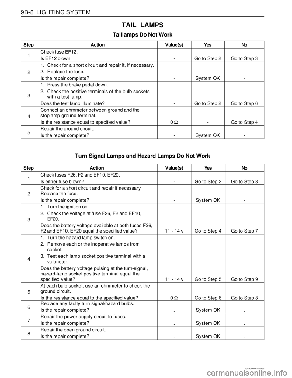
Turn Signal Lamps and Hazard Lamps Do Not Work
Step
1
2
3
4
5
6
7
8Action
Check fuses F26, F2 and EF10, EF20.
Is either fuse blown?
Check for a short circuit and repair if necessary
Replace the fuse.
Is the repair complete?
1. Turn the ignition on.
2. Check the voltage at fuse F26, F2 and EF10,
EF20.
Does the battery voltage available at both fuses F26,
F2 and EF10, EF20 equal the specified value?
1. Turn the hazard lamp switch on.
2. Remove each or the inoperative lamps from
socket.
3. Test each lamp socket positive terminal with a
voltmeter.
Does the battery voltage pulsing at the turn-signal,
hazard-lamp socket positive terminal equal the
specified value?
At each bulb socket, use an ohmmeter to check the
ground circuit.
Is the resistance equal to the specified value?
Replace any faulty turn signal/hazard bulbs.
Is the repair complete?
Repair the power supply circuit to fuses.
Is the repair complete?
Repair the open ground circuit.
Is the repair complete?Yes
Go to Step 2
System OK
Go to Step 4
Go to Step 5
Go to Step 6
System OK
System OK
System OKNo
Go to Step 3
-
Go to Step 7
Go to Step 9
Go to Step 8
-
-
- Value(s)
-
-
11 - 14 v
11 - 14 v
0 Ω
-
-
-
TAIL LAMPS
Taillamps Do Not Work
Step
1
2
3
4
5Action
Check fuse EF12.
Is EF12 blown.
1. Check for a short circuit and repair it, if necessary.
2. Replace the fuse.
Is the repair complete?
1. Press the brake pedal down.
2. Check the positive terminals of the bulb sockets
with a test lamp.
Does the test lamp illuminate?
Connect an ohmmeter between ground and the
stoplamp ground terminal.
Is the resistance equal to specified value?
Repair the ground circuit.
Is the repair complete?Yes
Go to Step 2
System OK
Go to Step 2
-
System OKNo
Go to Step 3
-
Go to Step 6
Go to Step 4
- Value(s)
-
-
-
0 Ω
-
Page 1871 of 2053
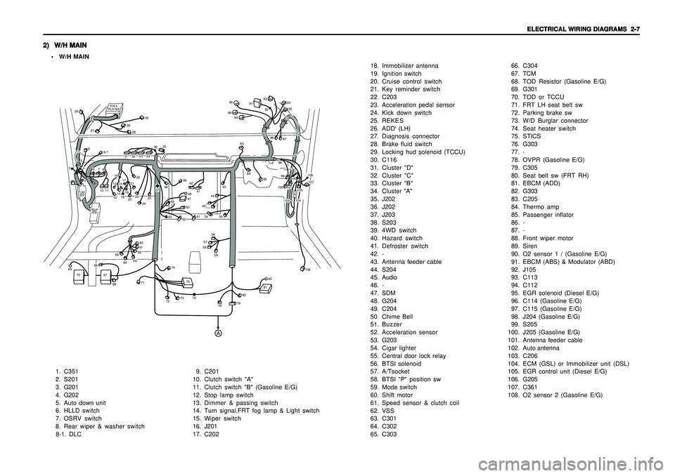
ELECTRICAL WIRING DIAGRAMS ELECTRICAL WIRING DIAGRAMSELECTRICAL WIRING DIAGRAMS ELECTRICAL WIRING DIAGRAMS
ELECTRICAL WIRING DIAGRAMS
2-7 2-7 2-7 2-7
2-7
2) 2)2) 2)
2)
W/H MAIN W/H MAINW/H MAIN W/H MAIN
W/H MAIN• W/H MAIN
1. C351
2. S201
3. G201
4. G202
5. Auto down unit
6. HLLD switch
7. OSRV switch
8. Rear wiper & washer switch
8-1. DLC9. C201
10. Clutch switch "A"
11. Clutch switch "B" (Gasoline E/G)
12. Stop lamp switch
13. Dimmer & passing switch
14. Turn signal,FRT fog lamp & Light switch
15. Wiper switch
16. J201
17. C20218. Immobilizer antenna
19. Ignition switch
20. Cruise control switch
21. Key reminder switch
22. C203
23. Acceleration pedal sensor
24. Kick down switch
25. REKES
26. ADD' (LH)
27. Diagnosis connector
28. Brake fluid switch
29. Locking hud solenoid (TCCU)
30. C116
31. Cluster "D"
32. Cluster "C"
33. Cluster "B"
34. Cluster "A"
35. J202
36. J202
37. J203
38. S203
39. 4WD switch
40. Hazard switch
41. Defroster switch
42. -
43. Antenna feeder cable
44. S204
45. Audio
46. -
47. SDM
48. G204
49. C204
50. Chime Bell
51. Buzzer
52. Acceleration sensor
53. G203
54. Cigar lighter
55. Central door lock relay
56. BTSI solenoid
57. A/Tsocket
58. BTSI "P" position sw
59. Mode switch
60. Shift motor
61. Speed sensor & clutch coil
62. VSS
63. C301
64. C302
65. C30366. C304
67. TCM
68. TOD Resistor (Gasoline E/G)
69. G301
70. TOD or TCCU
71. FRT LH seat belt sw
72. Parking brake sw
73. W/D Burglar connector
74. Seat heater switch
75. STICS
76. G303
77. -
78. OVPR (Gasoline E/G)
79. C305
80. Seat belt sw (FRT RH)
81. EBCM (ADD)
82. G303
83. C205
84. Thermo amp
85. Passenger inflator
86. -
87. -
88. Front wiper motor
89. Siren
90. O2 sensor 1 / (Gasoline E/G)
91. EBCM (ABS) & Modulator (ABD)
92. J105
93. C113
94. C112
95. EGR solenoid (Diesel E/G)
96. C114 (Gasoline E/G)
97. C115 (Gasoline E/G)
98. J204 (Gasoline E/G)
99. S205
100.J205 (Gasoline E/G)
101.Antenna feeder cable
102.Auto antenna
103.C206
104.ECM (GSL) or Immobilizer unit (DSL)
105.EGR control unit (Diesel E/G)
106. G205
107.C361
108. O2 sensor 2 (Gasoline E/G)
FUSE
BOX
RELAY
BOX
FUSE &
RELAY BOX
A
1011
12131415171618192021222829
30
26
27
31323334
35
3637
38
394041
43
83888990
91
93
9495
9296
979899102
101100
106107
104105
103
108
84
85
44
8-1
4748
49
50
51
52
53
45
55
54565758
60616263
6465
66
67
68
71
72
73
74
7576
78
7980
8182
69
70
59
232425
13
4259678