1997 SSANGYONG KORANDO air conditioning
[x] Cancel search: air conditioningPage 14 of 2053

0B -- 14 GENERAL INFORMATION
D AEW OO M Y_2000
EACH TIME THE OIL IS CHANGED
Brake System Inspection
This inspection should be done when the wheels are re-
moved for rotation. Inspect the lines and the hoses for
proper hookup, binding, leaks, cracks, chafing, etc. In-
spect the disc brake pads for wear. Inspect the rotors for
surface condition. Inspect other brake parts, the parking
brake, etc., at the same time. Inspect the brakes more
often if habit or conditions result in frequent braking.
Steering, Suspension and Front Drive Axle
Boot And Seal Inspection
Inspect the front and rear suspension and the steering
system for damaged, loose or missing parts, signs of
wear or lack of lubrication. Inspect the power steering
line and the hoses for proper hookup, binding, leaks,
cracks, chafing, etc. Clean and inspect the drive axle
boot and seals for damage, tears or leakage. Replace
the seals if necessary.
Exhaust System Inspection
Inspect the complete system (including the catalytic
converter if equipped). Inspect the body near the ex-
haust system. Look for broken, damaged, missing, or
out -- of -- position parts as well as open seams, holes,
loose connections, or other conditions which could
cause heat buildup in the floor pan or could let exhaust
fumes seep into the trunk or passenger compartment.
Throttle Linkage Inspection
Inspect the throttle linkage for interference or binding,
damaged, or missing parts. Lubricate all linkage joints
and throttle cable joints, the intermediate throttle shaft
bearing, the return spring at throttle valve assembly, and
the accelerator pedal sliding face with suitable grease.
Check the throttle cable for free movements.
Engine Drive Belts
Inspect all belts for cracks, fraying, wear and proper ten-
sion. Adjust or replace the belts as needed.
Hood Latch Operation
When opening the hood, note the operation of the sec-
ondary latch. It should keep the hood from opening all
the way when the primary latch is released. The hood
must close firmly.
AT LEAST ANNUALLY
Lap and Shoulder Belts Condition and Operation
Inspect the belt system including: the webbing, the
buckles, the latch plates, the retractor, the guide loops
and the anchors.
Movable Head Restraint Operation
On vehicles with movable head restraints, the restraints
must stay in the desired position.
Spare Tire and Jack Storage
Be alert to rattles in the rear of the vehicle. The spare
tire, all the jacking equipment, and the tools must be se-
curely stowed at all times. Oil the jack ratchet or the
screw mechanism after each use.
Key Lock Service
Lubricate the key lock cylinder.
Body Lubrication Service
Lubricate all the body door hinges including the hood,
the fuel door, the rear compartment hinges and the
latches, the glove box and the console doors, and any
folding seat hardware.
Underbody Flushing
Flushing the underbody will remove any corrosive mate-
rials used for ice and snow removal and dust control. At
least every spring clean the underbody. First, loosen the
sediment packed in closed areas of the vehicle. Then
flush the underbody with plain water.
Engine Cooling System
Inspect the coolant and freeze protection fluid. If the
fluid is dirty or rusty, drain, flush and refill the engine
cooling system with new coolant. Keep the coolant at
the proper mixture in order to ensure proper freeze
protection, corrosion protection and engine operating
temperature. Inspect the hoses. Replace the cracked,
swollen, or deteriorated hoses. Tighten the clamps.
Clean the outside of the radiator and the air conditioning
condenser. Wash the filler cap and the neck. Pressure
test the cooling system and the cap in order to help en-
sure proper operation.
Page 42 of 2053

1B1 -- 10 M162 ENGINE MECHANICAL
D AEW OO M Y_2000
13. Remove the hydraulic pipe of power steering.
Notice:Completely drain the oil.
14. Discharge the refrigerant from A/C system, and dis-
connect the discharge pipe and suction pipe from
the compressor. Refer toSection 7B, Manual Con-
trol Heating, Ventilation, and Air Conditioning Sys -
tem.
15. Remove the fuel feed and return line.
Notice:Before removing the fuel lines, release the pres-
sure in the fuel system.
Installation Notice
Tightening Torque
21 -- 25 NSm (15 -- 18 lb-ft)
16. Disconnect the terminals from the generator.
Page 1145 of 2053
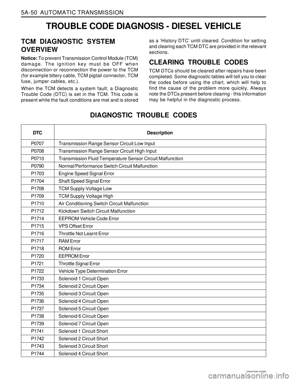
5A-50 AUTOMATIC TRANSMISSION
SSANGYONG MY2002
Transmission Range Sensor Circuit Low Input
Transmission Range Sensor Circuit High Input
Transmission Fluid Temperature Sensor Circuit Malfunction
Normal/Performance Switch Circuit Malfunction
Engine Speed Signal Error
Shaft Speed Signal Error
TCM Supply Voltage Low
TCM Supply Voltage High
Air Conditioning Switch Circuit Malfunction
Kickdown Switch Circuit Malfunction
EEPROM Vehicle Code Error
VPS Offset Error
Throttle Not Learnt Error
RAM Error
ROM Error
EEPROM Error
Throttle Signal Error
Vehicle Type Determination Error
Solenoid 1 Circuit Open
Solenoid 2 Circuit Open
Solenoid 3 Circuit Open
Solenoid 4 Circuit Open
Solenoid 5 Circuit Open
Solenoid 6 Circuit Open
Solenoid 7 Circuit Open
Solenoid 1 Circuit Short
Solenoid 2 Circuit Short
Solenoid 3 Circuit Short
Solenoid 4 Circuit Short
TROUBLE CODE DIAGNOSIS - DIESEL VEHICLE
TCM DIAGNOSTIC SYSTEM
OVERVIEW
Notice: To prevent Transmission Control Module (TCM)
damage. The ignition key must be OFF when
disconnection or reconnection the power to the TCM
(for example bttery cable, TCM pigtail connector, TCM
fuse, jumper cables, etc.).
When the TCM detects a system fault, a Diagnostic
Trouble Code (DTC) is set in the TCM. This code is
present while the fault conditions are met and is storedas a ‘History DTC’ until cleared. Condition for setting
and clearing each TCM DTC are provided in the relevant
sections.CLEARING TROUBLE CODES
TCM DTCs should be cleared after repairs have been
completed. Some diagnostic tables will tell you to clear
the codes before using the chart, which will help to
find the cause of the problem more quickly. Always
note the DTCs present before clearing - this information
may be helpful in the diagnostic process.
DIAGNOSTIC TROUBLE CODES
DTC
P0707
P0708
P0710
P0790
P1703
P1704
P1708
P1709
P1710
P1712
P1714
P1715
P1716
P1717
P1718
P1720
P1721
P1722
P1733
P1734
P1735
P1736
P1737
P1738
P1739
P1741
P1742
P1743
P1744Description
Page 1173 of 2053
5A-78 AUTOMATIC TRANSMISSION
SSANGYONG MY2002
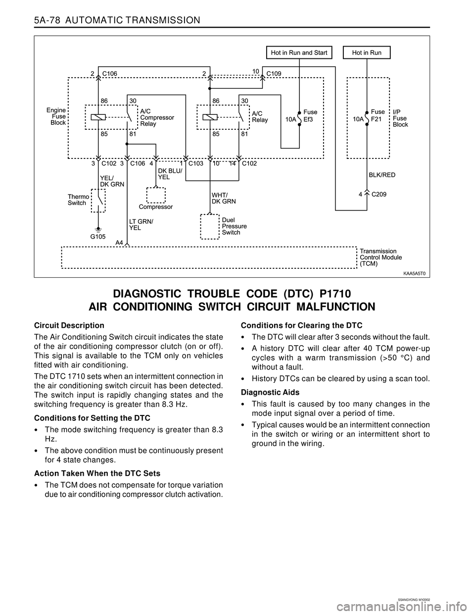
Circuit Description
The Air Conditioning Switch circuit indicates the state
of the air conditioning compressor clutch (on or off).
This signal is available to the TCM only on vehicles
fitted with air conditioning.
The DTC 1710 sets when an intermittent connection in
the air conditioning switch circuit has been detected.
The switch input is rapidly changing states and the
switching frequency is greater than 8.3 Hz.
Conditions for Setting the DTC
The mode switching frequency is greater than 8.3
Hz.
The above condition must be continuously present
for 4 state changes.
Action Taken When the DTC Sets
The TCM does not compensate for torque variation
due to air conditioning compressor clutch activation.
DIAGNOSTIC TROUBLE CODE (DTC) P1710
AIR CONDITIONING SWITCH CIRCUIT MALFUNCTION
Conditions for Clearing the DTC
The DTC will clear after 3 seconds without the fault.
A history DTC will clear after 40 TCM power-up
cycles with a warm transmission (>50 °C) and
without a fault.
History DTCs can be cleared by using a scan tool.
Diagnostic Aids
This fault is caused by too many changes in the
mode input signal over a period of time.
Typical causes would be an intermittent connection
in the switch or wiring or an intermittent short to
ground in the wiring.
KAA5A5T0
Page 1174 of 2053
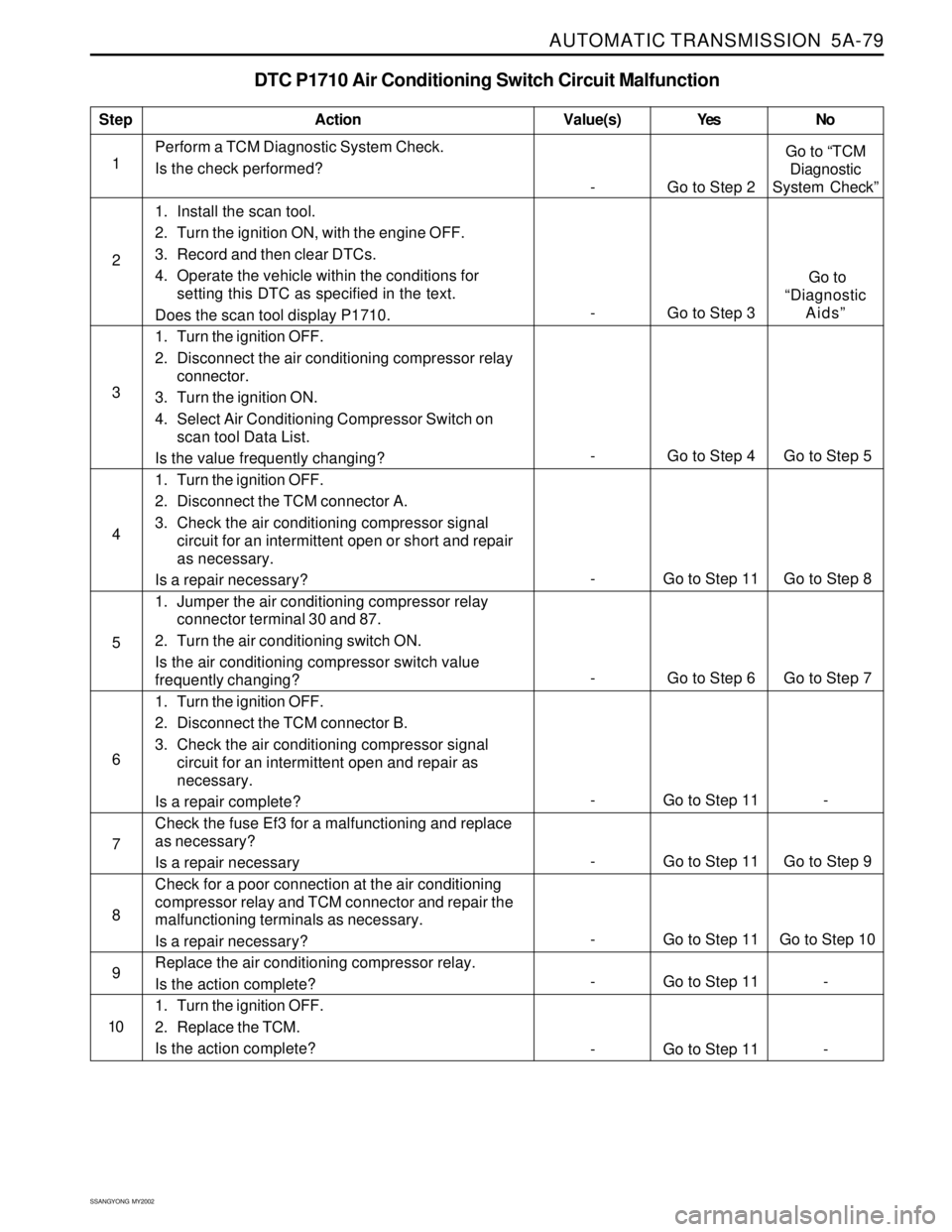
AUTOMATIC TRANSMISSION 5A-79
SSANGYONG MY2002
DTC P1710 Air Conditioning Switch Circuit Malfunction
1Perform a TCM Diagnostic System Check.
Is the check performed?
1. Install the scan tool.
2. Turn the ignition ON, with the engine OFF.
3. Record and then clear DTCs.
4. Operate the vehicle within the conditions for
setting this DTC as specified in the text.
Does the scan tool display P1710.
1. Turn the ignition OFF.
2. Disconnect the air conditioning compressor relay
connector.
3. Turn the ignition ON.
4. Select Air Conditioning Compressor Switch on
scan tool Data List.
Is the value frequently changing?
1. Turn the ignition OFF.
2. Disconnect the TCM connector A.
3. Check the air conditioning compressor signal
circuit for an intermittent open or short and repair
as necessary.
Is a repair necessary?
1. Jumper the air conditioning compressor relay
connector terminal 30 and 87.
2. Turn the air conditioning switch ON.
Is the air conditioning compressor switch value
frequently changing?
1. Turn the ignition OFF.
2. Disconnect the TCM connector B.
3. Check the air conditioning compressor signal
circuit for an intermittent open and repair as
necessary.
Is a repair complete?
Check the fuse Ef3 for a malfunctioning and replace
as necessary?
Is a repair necessary
Check for a poor connection at the air conditioning
compressor relay and TCM connector and repair the
malfunctioning terminals as necessary.
Is a repair necessary?
Replace the air conditioning compressor relay.
Is the action complete?
1. Turn the ignition OFF.
2. Replace the TCM.
Is the action complete?
StepAction Value(s) Yes No
2
3
4
5
- Go to Step 2Go to “TCM
Diagnostic
System Check”
6
7
8
9
10
- Go to Step 3 Go to
“Diagnostic
Aids”
- Go to Step 4 Go to Step 5
- Go to Step 11 Go to Step 8
- Go to Step 6 Go to Step 7
- Go to Step 11 -
- Go to Step 11 Go to Step 9
- Go to Step 11 Go to Step 10
- Go to Step 11 -
- Go to Step 11 -
Page 1175 of 2053
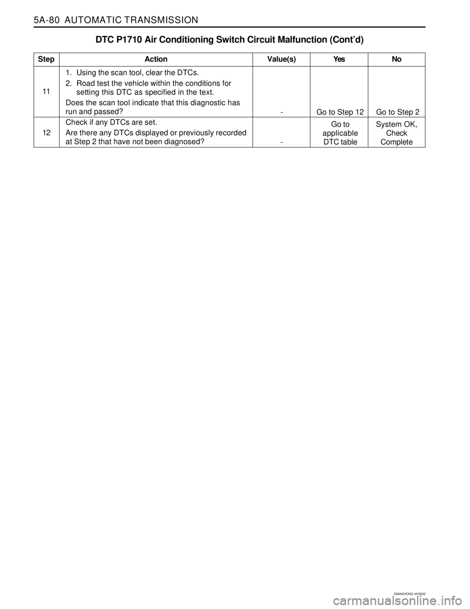
5A-80 AUTOMATIC TRANSMISSION
SSANGYONG MY2002
DTC P1710 Air Conditioning Switch Circuit Malfunction (Cont’d)
111. Using the scan tool, clear the DTCs.
2. Road test the vehicle within the conditions for
setting this DTC as specified in the text.
Does the scan tool indicate that this diagnostic has
run and passed?
Check if any DTCs are set.
Are there any DTCs displayed or previously recorded
at Step 2 that have not been diagnosed?
StepAction Value(s) Yes No
12
- Go to Step 12 Go to Step 2
-Go to
applicable
DTC tableSystem OK,
Check
Complete
Page 1505 of 2053
SSANGYONG MY2002
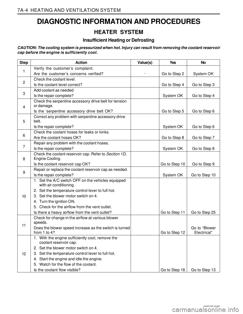
7A-4 HEATING AND VENTILATION SYSTEM
DIAGNOSTIC INFORMATION AND PROCEDURES
HEATER SYSTEM
Insufficient Heating or Defrosting
CAUTION: The cooling system is pressurized when hot. Injury can result from removing the coolant reservoir
cap before the engine is sufficiently cool.
Step
1
2
3
4
5
6
7
8
9
10
11
12
Action
Verify the customer’s complaint.
Are the customer’s concerns verified?
Check the coolant level.
Is the coolant level correct?
Add coolant as needed
Is the repair complete?
Check the serpentine accessory drive belt for tension
or damage.
Is the ’serpentine accessory drive belt OK?
Correct any problem with serpentine accessory drive
belt.
Is the repair complete?
Check the coolant hoses for leaks or kinks.
Are the coolant hoses OK?
Repair any problem with the coolant hoses.
Is the repair complete?
Check the coolant reservoir cap. Refer to Section 1D,
Engine Cooling.
Is the coolant reservoir cap OK?
Repair or replace the coolant reservoir cap as needed.
Is the repair complete?
1. Set the A/C switch OFF on the vehicles equipped
with air conditioning.
2. Set the temperature control lever to full hot.
3. Set the blower motor switch on 4.
4. Turn the ignition ON.
5. Check for the airflow from the vent outlet.
Is there a heavy airflow from the vent outlet?
Check for change in the airflow at various blower
speeds.
Does the blower speed increase as the switch is turned
from 1 to 4?
1. With the engine sufficiently cool, remove the
coolant reservoir cap.
2. Set the blower motor switch on 4.
3. Set the temperature control lever to full hot.
4. Start the engine and idle the engine.
5. Watch for the flow of the coolant.
Is the coolant flow visible?Yes
Go to Step 2
Go to Step 4
System OK
Go to Step 5
System OK
Go to Step 8
System OK
Go to Step 10
System OK
Go to Step 11
Go to Step 12
Go to Step 16No
System OK
Go to Step 3
Go to Step 4
Go to Step 6
Go to Step 6
Go to Step 7
Go to Step 8
Go to Step 9
Go to Step 10
Go to Step 25
Go to “Blower
Electrical”
Go to Step 13 Value(s)
-
Page 1530 of 2053
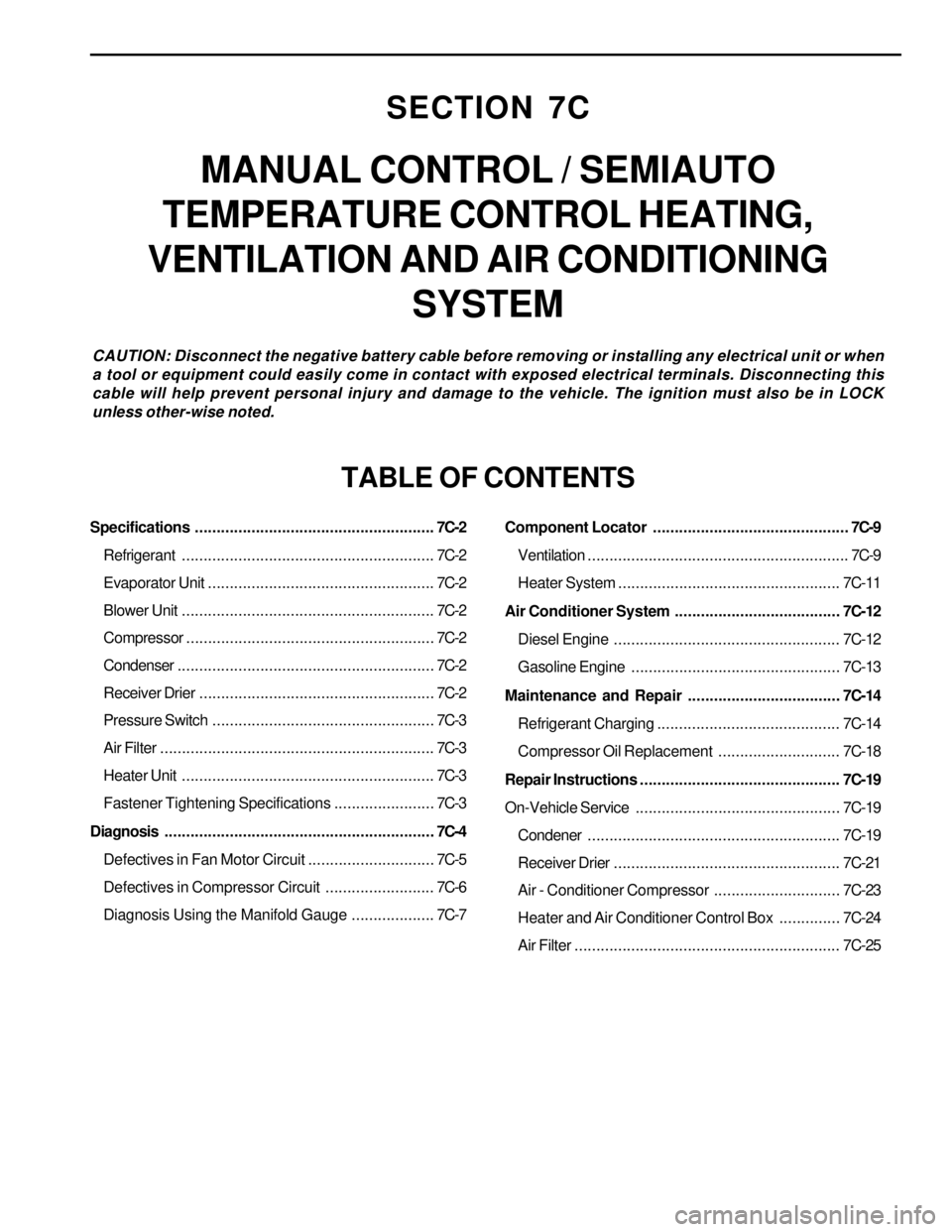
SECTION 7C
MANUAL CONTROL / SEMIAUTO
TEMPERATURE CONTROL HEATING,
VENTILATION AND AIR CONDITIONING
SYSTEM
CAUTION: Disconnect the negative battery cable before removing or installing any electrical unit or when
a tool or equipment could easily come in contact with exposed electrical terminals. Disconnecting this
cable will help prevent personal injury and damage to the vehicle. The ignition must also be in LOCK
unless other-wise noted.
TABLE OF CONTENTS
Specifications.......................................................7C-2
Refrigerant..........................................................7C-2
Evaporator Unit....................................................7C-2
Blower Unit..........................................................7C-2
Compressor.........................................................7C-2
Condenser...........................................................7C-2
Receiver Drier......................................................7C-2
Pressure Switch...................................................7C-3
Air Filter...............................................................7C-3
Heater Unit..........................................................7C-3
Fastener Tightening Specifications.......................7C-3
Diagnosis..............................................................7C-4
Defectives in Fan Motor Circuit.............................7C-5
Defectives in Compressor Circuit.........................7C-6
Diagnosis Using the Manifold Gauge...................7C-7Component Locator.............................................7C-9
Ventilation............................................................7C-9
Heater System ................................................... 7C-11
Air Conditioner System...................................... 7C-12
Diesel Engine .................................................... 7C-12
Gasoline Engine................................................ 7C-13
Maintenance and Repair................................... 7C-14
Refrigerant Charging .......................................... 7C-14
Compressor Oil Replacement............................ 7C-18
Repair Instructions.............................................. 7C-19
On-Vehicle Service............................................... 7C-19
Condener.......................................................... 7C-19
Receiver Drier.................................................... 7C-21
Air - Conditioner Compressor............................. 7C-23
Heater and Air Conditioner Control Box.............. 7C-24
Air Filter............................................................. 7C-25