1997 MITSUBISHI TRITON lock
[x] Cancel search: lockPage 1027 of 1310
6
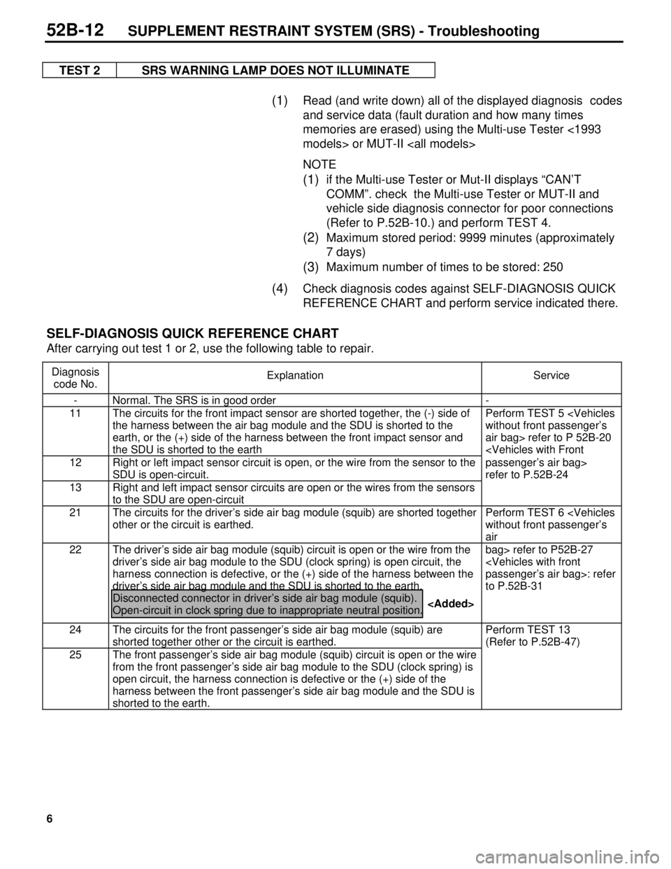
TEST 2 SRS WARNING LAMP DOES NOT ILLUMINATE
(1) Read (and write down) all of the displayed diagnosis codes
and service data (fault duration and how many times
memories are erased) using the Multi-use Tester <1993
models> or MUT-II
NOTE
(1) if the Multi-use Tester or Mut-II displays “CAN’T
COMM”. check the Multi-use Tester or MUT-II and
vehicle side diagnosis connector for poor connections
(Refer to P.52B-10.) and perform TEST 4.
(2) Maximum stored period: 9999 minutes (approximately
7 days)
(3) Maximum number of times to be stored: 250
(4) Check diagnosis codes against SELF-DIAGNOSIS QUICK
REFERENCE CHART and perform service indicated there.
SELF-DIAGNOSIS QUICK REFERENCE CHART
After carrying out test 1 or 2, use the following table to repair.
Diagnosis
code No.Explanation Service
- Normal. The SRS is in good order -
11 The circuits for the front impact sensor are shorted together, the (-) side of
the harness between the air bag module and the SDU is shorted to the
earth, or the (+) side of the harness between the front impact sensor and
the SDU is shorted to the earthPerform TEST 5
air bag> refer to P 52B-20
SDU is open-circuit.passenger’s air bag>
refer to P.52B-24
13 Right and left impact sensor circuits are open or the wires from the sensors
to the SDU are open-circuit
21 The circuits for the driver’s side air bag module (squib) are shorted together
other or the circuit is earthed.Perform TEST 6
air
22 The driver’s side air bag module (squib) circuit is open or the wire from the
driver’s side air bag module to the SDU (clock spring) is open circuit, the
harness connection is defective, or the (+) side of the harness between the
driver’s side air bag module and the SDU is shorted to the earth.
Disconnected connector in driver’s side air bag module (squib).
Open-circuit in clock spring due to inappropriate neutral position.bag> refer to P52B-27
to P.52B-31
24 The circuits for the front passenger’s side air bag module (squib) are
shorted together other or the circuit is earthed.Perform TEST 13
(Refer to P.52B-47)
25 The front passenger’s side air bag module (squib) circuit is open or the wire
from the front passenger’s side air bag module to the SDU (clock spring) is
open circuit, the harness connection is defective or the (+) side of the
harness between the front passenger’s side air bag module and the SDU is
shorted to the earth.
52B-12SUPPLEMENT RESTRAINT SYSTEM (SRS) - Troubleshooting
Page 1031 of 1310
10
TROUBLESHOOTING
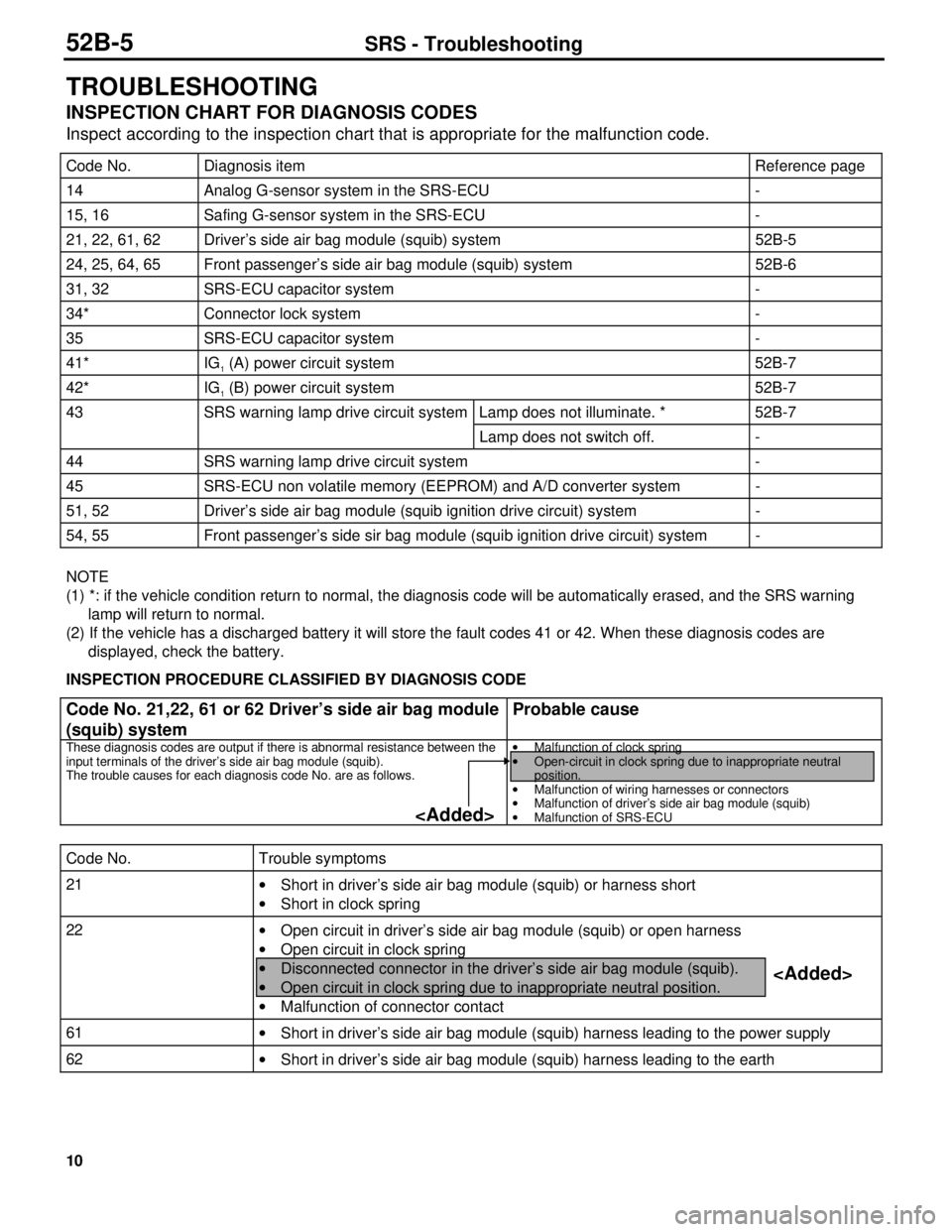
INSPECTION CHART FOR DIAGNOSIS CODES
Inspect according to the inspection chart that is appropriate for the malfunction code.
Code No. Diagnosis item Reference page
14 Analog G-sensor system in the SRS-ECU -
15, 16 Safing G-sensor system in the SRS-ECU -
21, 22, 61, 62 Driver’s side air bag module (squib) system 52B-5
24, 25, 64, 65 Front passenger’s side air bag module (squib) system 52B-6
31, 32 SRS-ECU capacitor system -
34* Connector lock system -
35 SRS-ECU capacitor system -
41* IG1 (A) power circuit system 52B-7
42* IG1 (B) power circuit system 52B-7
43 SRS warning lamp drive circuit system Lamp does not illuminate. * 52B-7
Lamp does not switch off. -
44 SRS warning lamp drive circuit system -
45 SRS-ECU non volatile memory (EEPROM) and A/D converter system -
51, 52 Driver’s side air bag module (squib ignition drive circuit) system -
54, 55 Front passenger’s side sir bag module (squib ignition drive circuit) system -
NOTE
(1) *: if the vehicle condition return to normal, the diagnosis code will be automatically erased, and the SRS warning
lamp will return to normal.
(2) If the vehicle has a discharged battery it will store the fault codes 41 or 42. When these diagnosis codes are
displayed, check the battery.
INSPECTION PROCEDURE CLASSIFIED BY DIAGNOSIS CODE
Code No. 21,22, 61 or 62 Driver’s side air bag module
(squib) systemProbable cause
These diagnosis codes are output if there is abnormal resistance between the
input terminals of the driver’s side air bag module (squib).
The trouble causes for each diagnosis code No. are as follows.·
Malfunction of clock spring
·
Open-circuit in clock spring due to inappropriate neutral
position.
·
Malfunction of wiring harnesses or connectors
·
Malfunction of driver’s side air bag module (squib)
·
Malfunction of SRS-ECU
Code No. Trouble symptoms
21
·
Short in driver’s side air bag module (squib) or harness short
·
Short in clock spring
22
·
Open circuit in driver’s side air bag module (squib) or open harness
·
Open circuit in clock spring
·
Disconnected connector in the driver’s side air bag module (squib).
·
Open circuit in clock spring due to inappropriate neutral position.
·
Malfunction of connector contact
61
·
Short in driver’s side air bag module (squib) harness leading to the power supply
62
·
Short in driver’s side air bag module (squib) harness leading to the earth
52B-5SRS - Troubleshooting
Page 1035 of 1310
14
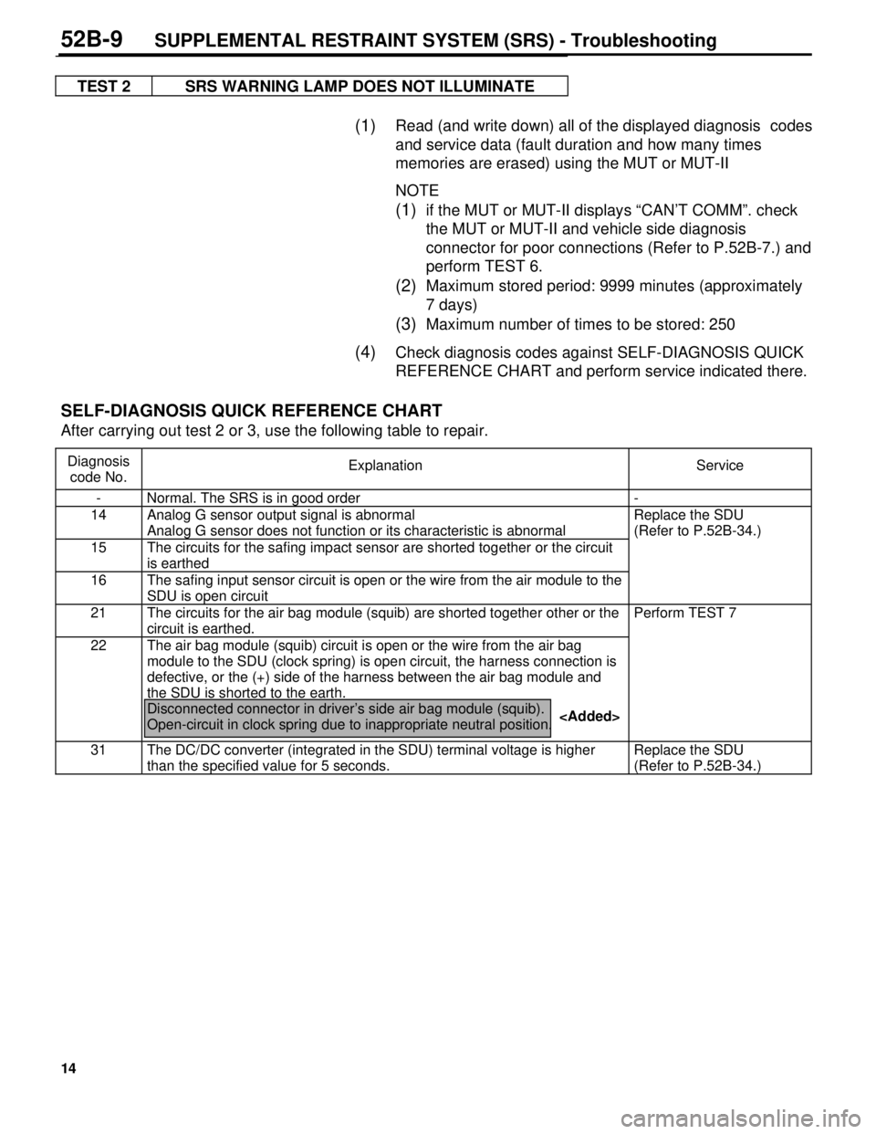
TEST 2 SRS WARNING LAMP DOES NOT ILLUMINATE
(1) Read (and write down) all of the displayed diagnosis codes
and service data (fault duration and how many times
memories are erased) using the MUT or MUT-II
NOTE
(1) if the MUT or MUT-II displays “CAN’T COMM”. check
the MUT or MUT-II and vehicle side diagnosis
connector for poor connections (Refer to P.52B-7.) and
perform TEST 6.
(2) Maximum stored period: 9999 minutes (approximately
7 days)
(3) Maximum number of times to be stored: 250
(4) Check diagnosis codes against SELF-DIAGNOSIS QUICK
REFERENCE CHART and perform service indicated there.
SELF-DIAGNOSIS QUICK REFERENCE CHART
After carrying out test 2 or 3, use the following table to repair.
Diagnosis
code No.Explanation Service
- Normal. The SRS is in good order -
14 Analog G sensor output signal is abnormal
Analog G sensor does not function or its characteristic is abnormalReplace the SDU
(Refer to P.52B-34.)
15 The circuits for the safing impact sensor are shorted together or the circuit
is earthed
16 The safing input sensor circuit is open or the wire from the air module to the
SDU is open circuit
21 The circuits for the air bag module (squib) are shorted together other or the
circuit is earthed.Perform TEST 7
22 The air bag module (squib) circuit is open or the wire from the air bag
module to the SDU (clock spring) is open circuit, the harness connection is
defective, or the (+) side of the harness between the air bag module and
the SDU is shorted to the earth.
Disconnected connector in driver’s side air bag module (squib).
Open-circuit in clock spring due to inappropriate neutral position.
31 The DC/DC converter (integrated in the SDU) terminal voltage is higher
than the specified value for 5 seconds.Replace the SDU
(Refer to P.52B-34.)
52B-9SUPPLEMENTAL RESTRAINT SYSTEM (SRS) - Troubleshooting
Page 1036 of 1310
15
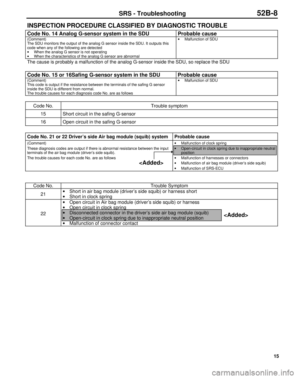
INSPECTION PROCEDURE CLASSIFIED BY DIAGNOSTIC TROUBLE
Code No. 14 Analog G-sensor system in the SDU Probable cause
(Comment)
The SDU monitors the output of the analog G sensor inside the SDU. It outputs this
code when any of the following are detected
·
When the analog G sensor is not operating
·
When the characteristics of the analog G sensor are abnormal·
Malfunction of SDU
The cause is probably a malfunction of the analog G-sensor inside the SDU, so replace the SDU
Code No. 15 or 16Safing G-sensor system in the SDU Probable cause
(Comment)
This code is output if the resistance between the terminals of the safing G sensor
inside the SDU is different from normal.
The trouble causes for each diagnosis code No. are as follows·
Malfunction of SDU
Code No. Trouble symptom
15 Short circuit in the safing G-sensor
16 Open circuit in the safing G-sensor
Code No. 21 or 22 Driver’s side Air bag module (squib) system Probable cause
(Comment)
These diagnosis codes are output if there is abnormal resistance between the input
terminals of the air bag module (driver’s side squib).
The trouble causes for each code No. are as follows·
Malfunction of clock spring
·
Open-circuit in clock spring due to inappropriate neutral
position
·
Malfunction of harnesses or connectors
·
Malfunction of air bag module (driver’s side squib)
·
Malfunction of SRS-ECU
Code No. Trouble Symptom
21·
Short in air bag module (driver’s side squib) or harness short
·
Short in clock spring
22·
Open circuit in Air bag module (driver’s side squib) or harness
·
Open circuit in clock spring
·
Disconnected connector in the driver’s side air bag module (squib)
·
Open-circuit in clock spring due to inappropriate neutral position
·
Malfunction of connector contact
SRS - Troubleshooting52B-8
Page 1042 of 1310
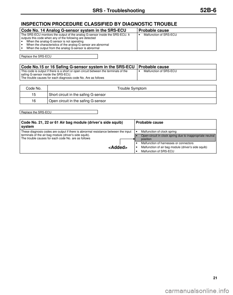
21
INSPECTION PROCEDURE CLASSIFIED BY DIAGNOSTIC TROUBLE
Code No. 14 Analog G-sensor system in the SRS-ECU Probable cause
The SRS-ECU monitors the output of the analog G-sensor inside the SRS-ECU. It
outputs this code when any of the following are detected
·
When the analog-G sensor is not operating
·
When the characteristics of the analog-G sensor are abnormal
·
When the output from the analog G-sensor is abnormal·
Malfunction of SRS-ECU
Replace the SRS-ECU
Code No.15 or 16 Safing G-sensor system in the SRS-ECU Probable cause
This code is output if there is a short or open circuit between the terminals of the
safing G-sensor inside the SRS-ECU.
The trouble causes for each diagnosis code No. Are as follows·
Malfunction of SRS-ECU
Code No. Trouble Symptom
15 Short circuit in the safing G-sensor
16 Open circuit in the safing G-sensor
Replace the SRS-ECU
Code No. 21, 22 or 61 Air bag module (driver’s side squib)
systemProbable cause
These diagnosis codes are output if there is abnormal resistance between the input
terminals of the air bag module (driver’s side squib).
The trouble causes for each code No. are as follows·
Malfunction of clock spring
·
Open-circuit in clock spring due to inappropriate neutral
position
·
Malfunction of harnesses or connectors
·
Malfunction of air bag module (driver’s side squib)
·
Malfunction of SRS-ECU
SRS - Troubleshooting52B-6
Page 1044 of 1310
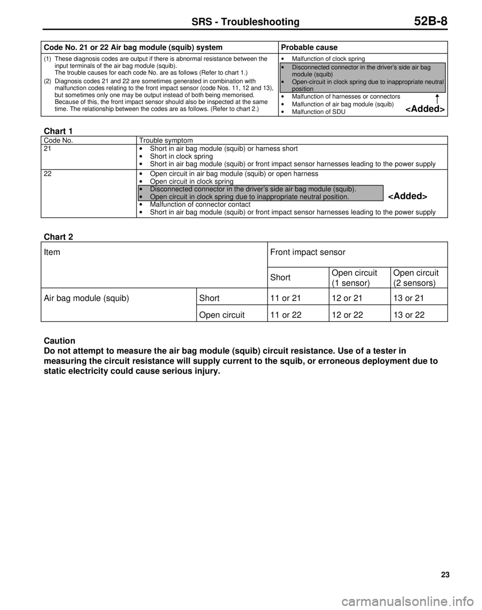
23
Code No. 21 or 22 Air bag module (squib) system Probable cause
(1) These diagnosis codes are output if there is abnormal resistance between the
input terminals of the air bag module (squib).
The trouble causes for each code No. are as follows (Refer to chart 1.)
(2) Diagnosis codes 21 and 22 are sometimes generated in combination with
malfunction codes relating to the front impact sensor (code Nos. 11, 12 and 13),
but sometimes only one may be output instead of both being memorised.
Because of this, the front impact sensor should also be inspected at the same
time. The relationship between the codes are as follows. (Refer to chart 2.)·
Malfunction of clock spring
·
Disconnected connector in the driver’s side air bag
module (squib)
·
Open-circuit in clock spring due to inappropriate neutral
position
·
Malfunction of harnesses or connectors
·
Malfunction of air bag module (squib)
·
Malfunction of SDU
Chart 1
Code No. Trouble symptom
21
· Short in air bag module (squib) or harness short
· Short in clock spring
· Short in air bag module (squib) or front impact sensor harnesses leading to the power supply
22
· Open circuit in air bag module (squib) or open harness
· Open circuit in clock spring
· Disconnected connector in the driver’s side air bag module (squib).
· Open circuit in clock spring due to inappropriate neutral position.
· Malfunction of connector contact
· Short in air bag module (squib) or front impact sensor harnesses leading to the power supply
Chart 2
Item Front impact sensor
ShortOpen circuit
(1 sensor)Open circuit
(2 sensors)
Air bag module (squib) Short 11 or 21 12 or 21 13 or 21
Open circuit 11 or 22 12 or 22 13 or 22
Caution
Do not attempt to measure the air bag module (squib) circuit resistance. Use of a tester in
measuring the circuit resistance will supply current to the squib, or erroneous deployment due to
static electricity could cause serious injury.
SRS - Troubleshooting52B-8
Page 1073 of 1310

14
LUBRICANTS
Items Specified lubricant Quantity
Manual steering gear oil Hypoid gear oil API
GL-4 or higher SAE 80210 cm3 (12.81 cu.in.)
Power steering fluid
L.H. drive vehicles
<2800D>11.1 dm3 (1.17 U.S.qts.,
0.98 lmp.qts.)
0.93 lmp.qts.)
R.H. drive vehicels Automatic transmission fluid
DEXRON or DEXRON II
<2800D>1.02 dm3 (1,08 U.S.qts.,
0.90 lmp.qts.)
0.85 lmp.qts.)
Power steering gear box
Bearing, O-ring and oil seal
Automatic transmission fluid
DEXRON or DEXRON IIAs required
Oil pump
Flow control valve and O-ring
Friction surface of rotor, vane, cam ring
and pump coverAutomatic transmission fluid
DEXRON or DEXRON IIAs required
SEALANTS AND ADHESIVES
Items Specified sealant and adhesive Remarks
Steering column cover assembly
installation hole
Dash panel cover installed surface
Manual steering gear box top cover
packing
Manual steering gear box cross-shaft
adjusting and lock nut3M ATD Part No. 861 or equivalent Semi-drying sealant
Manual steering gear box top cover bolt
Manual steering gear box adjusting shim
Tie-rod end dust cover installed surface
Inside of steering column lower pipe
bearing
Connection of steering column upper and
steering column lower (Nut side)3M Stud Locking Part No. 4170 or
equivalentSemi-drying sealant
Steering column upper bearing 3M ATD Part No. 8001 or equivalent Semi-drying sealant
37-4STEERING – Specifications
E37CD--
E37CE--
Page 1075 of 1310
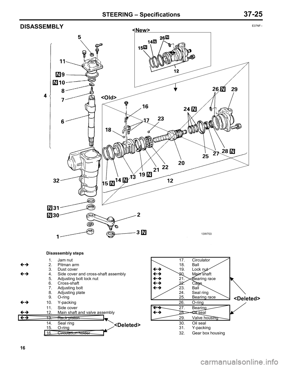
0
3. Dust c o ve r !
"
19. Lock n ut 0
5. Adju stin g b olt lo ck n ut !
"
21. Bearin g r a ce 0
6 . Cro ss-s h aft !
"
22. Cage 0
7. Adju stin g b olt !
"
23. Ball 0
8. Adju stin g p la te 24. Seal r in g 0
9. O-rin g 25. Bearin g r a ce 1
1. Sid e c o ve r !
"
27. Bearin g 1
4. Seal r in g 30. Oil s e a l 1
5. O-rin g 31. Y-p ackin g
1 6. Cir c u la tio n h old er 32. Gear b ox h ousin g <
D ele te d >