1997 MERCEDES-BENZ ML500 ad blue
[x] Cancel search: ad bluePage 3106 of 4133
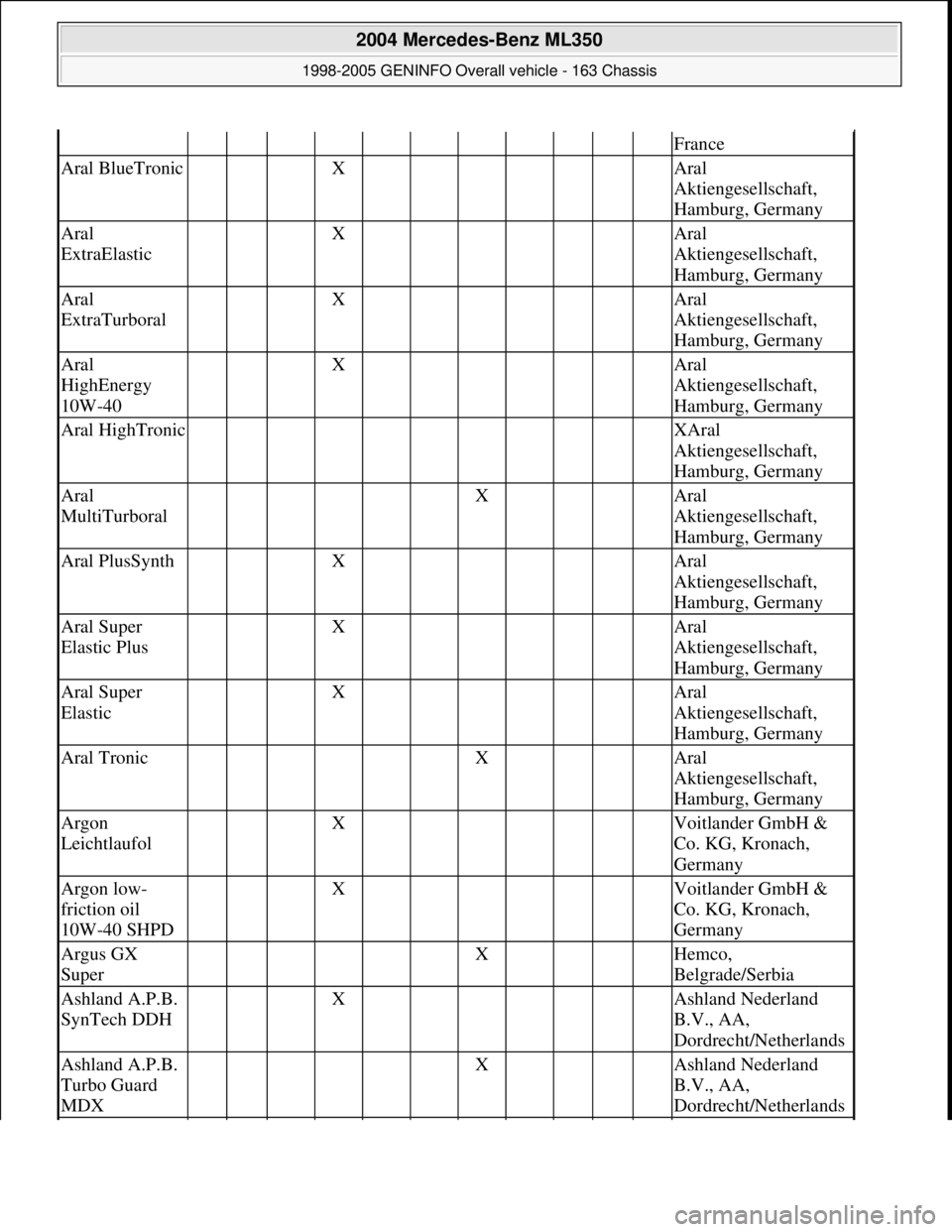
France
Aral BlueTronic X Aral
Aktiengesellschaft,
Hamburg, Germany
Aral
ExtraElastic X Aral
Aktiengesellschaft,
Hamburg, Germany
Aral
ExtraTurboral X Aral
Aktiengesellschaft,
Hamburg, Germany
Aral
HighEnergy
10W-40 X Aral
Aktiengesellschaft,
Hamburg, Germany
Aral HighTronic XAral
Aktiengesellschaft,
Hamburg, Germany
Aral
MultiTurboral X Aral
Aktiengesellschaft,
Hamburg, Germany
Aral PlusSynth X Aral
Aktiengesellschaft,
Hamburg, Germany
Aral Super
Elastic Plus X Aral
Aktiengesellschaft,
Hamburg, Germany
Aral Super
Elastic X Aral
Aktiengesellschaft,
Hamburg, Germany
Aral Tronic X Aral
Aktiengesellschaft,
Hamburg, Germany
Argon
Leichtlaufol X Voitlander GmbH &
Co. KG, Kronach,
Germany
Argon low-
friction oil
10W-40 SHPD X Voitlander GmbH &
Co. KG, Kronach,
Germany
Argus GX
Super X Hemco,
Belgrade/Serbia
Ashland A.P.B.
SynTech DDH X Ashland Nederland
B.V., AA,
Dordrecht/Netherlands
Ashland A.P.B.
Turbo Guard
MDX X Ashland Nederland
B.V., AA,
Dordrecht/Netherlands
2004 Mercedes-Benz ML350
1998-2005 GENINFO Overall vehicle - 163 Chassis
me
Saturday, October 02, 2010 3:47:54 PMPage 461 © 2006 Mitchell Repair Information Company, LLC.
Page 3189 of 4133

AF18.00-P-8045A
High oil consumption, blue smoke
26.10.99
ENGINE
112 in MODEL 129, 163, 202, 208, 210
ENGINE
112 in MODEL 463
Modification notes
18.11.99
Supersedes STIP 18.40-004 dated 5.11.97
Remedy revised
Damage code
Cause
Remedy
01 241 B2
Cast iron crust in oil drain duct on right
cylinder head, inner rear
1
Remove right cylinder head.
#
In case of complaint oil drain duct is filled
with engine oil.
Engine 112 in model 129, 202, 208, 210
AR01.30-P-5800B
Engine 112.942 in model 163.154
AR01.30-P-5800MV
Engine 112.945 in model 463
AR01.30-P-5800GV
2
Remove present cast iron crust.
Use sharp edged 10 mm punch. The cast
iron crust (approx. 11x17x1 mm) is located
approx. 50 mm below the upper cylinder head
separating surface.
3
Install right cylinder head
#
Engine 112 in model 129
AR01.30-P-5800B
Engine 112 in model 202, 208, 210
AR01.30-P-5800BA
Engine 112.942 in model 163.154
AR01.30-P-5800MV
Engine 112.945 in model 463
AR01.30-P-5800GV
Copyright DaimlerChrysler AG 20.05.2006 CD-Ausgabe G/10/04 . This WIS print-out will not be recorde
d by Modification services.
Page 1
Page 3221 of 4133
TESTS.
Normal Ventilation In Regulating Mode
To check normal ventilation in regulating mode, set temperature selector knob to White range (vertical). Set
mode control knob to 4-o'clock position. Ensure A/C button indicator is illuminated. Air will vent from upper
and lower outlets and A/C compressor will engage. Ambient air will flow from center outlet and coolant
circulation pump will operate. If operation is not as specified, perform the following in order:
Check A/C button activation. See A/C BUTTON under ELECTRICAL TESTS.
Check A/C pressure switch. See A/C REFRIGERANT PRESSURE SWITCH under ELECTRICAL
TESTS.
Economy Setting Not In Heating Mode
To check economy setting without heating mode activated, set temperature selector knob to Blue range. Set
mode control knob to the 9-o'clock position. Ensure A/C button indicator is not illuminated. Ambient air will
flow from center outlet and A/C compressor will NOT be engaged. If operation is not as specified, perform the
following:
Check A/C button activation. See A/C BUTTON under ELECTRICAL TESTS.
Economy Setting In Heating Mode
To check economy setting with heating mode activated, set temperature selector knob to Red range. Set mode
control knob to the 4-o'clock position. Ensure A/C button indicator is not illuminated. Heated air will flow from
lower, upper and center outlets and A/C compressor will NOT be engaged. If operation is not as specified,
perform the following:
Check A/C button activation. See A/C BUTTON under ELECTRICAL TESTS.
Recirculation Mode
To check recirculation mode, press fresh/recirculation button. Ensure fresh/recirculation indicator is
illuminated. Set blower speed knob to position No. 4. Blower fan noise will increase noticeably. If operation is
not as specified, check wiring between recirculated air flap element, heater-A/C switch and No. 16 fuse (15-
amp).
ELECTRICAL TESTS
Voltage Supply Circuit Z50/2
1. Connect socket box to A/C push button control unit and wiring harness. See CONNECTING TEST
EQUIPMENT . Turn ignition on, with engine off. Connect voltmeter positive lead to socket box terminal
No. 7 and negative lead to terminal No. 9.
2. Voltage should be 11-14 volts. If voltage is not as specified, check voltage supply circuit Z50/2 between
No. 16 fuse (15-amp) and connected components. See WIRING DIAGRAMS
. Repair as necessary.
2001 Mercedes-Benz ML320
2000-01 MANUAL A/C-HEATER SYSTEMS ML 320, ML 430 & ML 55
me
Saturday, October 02, 2010 3:25:10 PMPage 10 © 2006 Mitchell Repair Information Company, LLC.
Page 3223 of 4133
4. If resistance is not as specified, check wiring harness between temperature sensor and control unit. Repair
as necessary. If wiring harness is okay, replace icing protection temperature sensor.
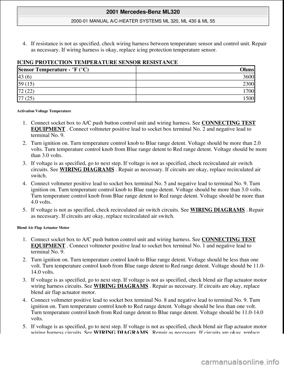
ICING PROTECTION TEMPERATURE SENSOR RESISTANCE
Activation Voltage Temperature
1. Connect socket box to A/C push button control unit and wiring harness. See CONNECTING TEST
EQUIPMENT . Connect voltmeter positive lead to socket box terminal No. 2 and negative lead to
terminal No. 9.
2. Turn ignition on. Turn temperature control knob to Blue range detent. Voltage should be more than 2.0
volts. Turn temperature control knob from Blue range detent to Red range detent. Voltage should be more
than 3.0 volts.
3. If voltage is as specified, go to next step. If voltage is not as specified, check recirculated air switch
circuits. See WIRING DIAGRAMS
. Repair as necessary. If circuits are okay, replace recirculated air
switch.
4. Connect voltmeter positive lead to socket box terminal No. 5 and negative lead to terminal No. 9. Turn
ignition on. Turn temperature control knob to Blue range detent. Voltage should be more than 3.0 volts.
Turn temperature control knob from Blue range detent to Red range detent. Voltage should be more than
4.0 volts.
5. If voltage is not as specified, check recirculated air switch circuits. See WIRING DIAGRAMS
. Repair
as necessary. If circuits are okay, replace recirculated air switch.
Blend Air Flap Actuator Motor
1. Connect socket box to A/C push button control unit and wiring harness. See CONNECTING TEST
EQUIPMENT . Connect voltmeter positive lead to socket box terminal No. 1 and negative lead to
terminal No. 9.
2. Turn ignition on. Turn temperature control knob to Blue range detent. Voltage should be less than one
volt. Turn temperature control knob from Blue range detent to Red range detent. Voltage should be 11.0-
14.0 volts.
3. If voltage is as specified, go to next step. If voltage is not as specified, check blend air flap actuator motor
wiring harness circuits. See WIRING DIAGRAMS
. Repair as necessary. If circuits are okay, replace
blend air flap actuator motor.
4. Connect voltmeter positive lead to socket box terminal No. 8 and negative lead to terminal No. 9. Turn
ignition on. Turn temperature control knob to Red range detent. Voltage should be less than one volt.
Turn temperature control knob from Red range detent to Blue range detent. Voltage should be 11.0-14.0
volts.
5. If voltage is as specified, go to next step. If voltage is not as specified, check blend air flap actuator motor
wiring harness circuits. See WIRING DIAGRAMS
. Repair as necessary. If circuits are okay, replace
Sensor Temperature - °F (°C)Ohms
43 (6)3600
59 (15)2300
72 (22)1700
77 (25)1500
2001 Mercedes-Benz ML320
2000-01 MANUAL A/C-HEATER SYSTEMS ML 320, ML 430 & ML 55
me
Saturday, October 02, 2010 3:25:10 PMPage 12 © 2006 Mitchell Repair Information Company, LLC.
Page 3250 of 4133
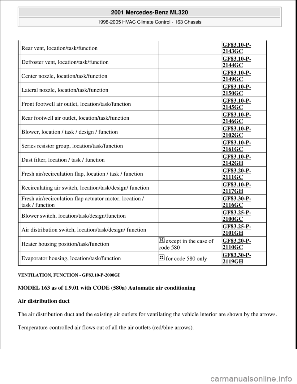
VENTILATION, FUNCTION - GF83.10-P-2000GI
MODEL 163 as of 1.9.01 with CODE (580a) Automatic air conditioning
Air distribution duct
The air distribution duct and the existing air outlets for ventilating the vehicle interior are shown by the arrows.
Temperature-controlled air flows out of all the air outlets (red/blue arrows).
Rear vent, location/task/function GF83.10-P-
2143GC
Defroster vent, location/task/function GF83.10-P-
2144GC
Center nozzle, location/task/function GF83.10-P-
2149GC
Lateral nozzle, location/task/function GF83.10-P-
2150GC
Front footwell air outlet, location/task/function GF83.10-P-
2145GC
Rear footwell air outlet, location/task/function GF83.10-P-
2146GC
Blower, location / task / design / function GF83.10-P-
2102GC
Series resistor group, location/task/function GF83.10-P-
2161GC
Dust filter, location / task / function GF83.10-P-
2142GH
Fresh air/recirculation flap, location / task / function GF83.20-P-
2111GC
Recirculating air switch, location/task/design/ function GF83.10-P-
2117GH
Fresh air/recirculation flap actuator motor, location /
task / function GF83.30-P-
2116GC
Blower switch, location/task/design/function GF83.25-P-
2100GC
Air distribution switch, location/task/design/ function GF83.25-P-
2101GH
Heater housing position/task/function except in the case of
code 580GF83.20-P-
2110GC
Evaporator housing, location/task/function for code 580 onlyGF83.30-P-
2119GH
2001 Mercedes-Benz ML320
1998-2005 HVAC Climate Control - 163 Chassis
me
Saturday, October 02, 2010 3:23:14 PMPage 6 © 2006 Mitchell Repair Information Company, LLC.
Page 3288 of 4133
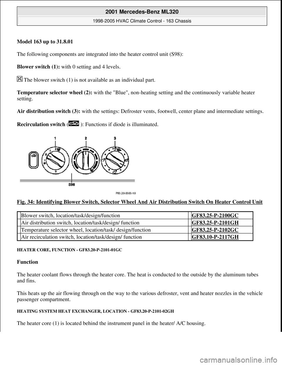
Model 163 up to 31.8.01
The following components are integrated into the heater control unit (S98):
Blower switch (1): with 0 setting and 4 levels.
The blower switch (1) is not available as an individual part.
Temperature selector wheel (2): with the "Blue", non-heating setting and the continuously variable heater
setting.
Air distribution switch (3): with the settings: Defroster vents, footwe ll, center plane and intermediate settings.
Recirculation switch ( ): Functions if diode is illuminated.
Fig. 34: Identifying Blower Switch, Selector Wheel And Air Distribution Switch On Heater Control Unit
HEATER CORE, FUNCTI ON - GF83.20-P-2101-01GC
Function
The heater coolant flows through the heater core. The he at is conducted to the outside by the aluminum tubes
and fins.
This heats up the air flowing through on the way to the vari ous defroster, vent and heater nozzles in the vehicle
passenger compartment.
HEATING SYSTEM HEAT EXCHANGE R, LOCATION - GF83.20-P-2101-02GH
The heater core (1) is located behind the instrument panel in the heater/ A/C housing.
Blower switch, location/task/design/function GF83.25-P-2100GC
Air distribution switch, locat ion/task/design/ function GF83.25-P-2101GH
Temperature selector wheel, location/task/ design/function GF83.25-P-2102GC
Air recirculation switch, loca tion/task/design/ function GF83.10-P-2117GH
2001 Mercedes-Benz ML320
1998-2005 HVAC Climate Control - 163 Chassis
me
Saturday, October 02, 2010 3:23:15 PMPage 44 © 2006 Mitchell Repair Information Company, LLC.
Page 3309 of 4133
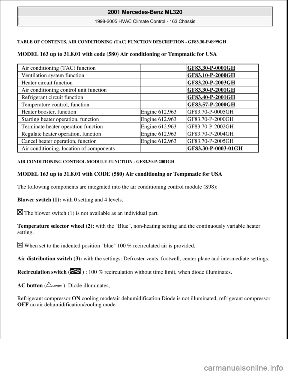
TABLE OF CONTENTS, AIR CONDITIONING (TAC) FUNCTION DESCRIPTION - GF83.30-P-0999GH
MODEL 163 up to 31.8.01 with code (580) Air conditioning or Tempmatic for USA
AIR CONDITIONING CONTROL MODULE FUNCTION - GF83.30-P-2001GH
MODEL 163 up to 31.8.01 with CODE (580) Air conditioning or Tempmatic for USA
The following components are integrated into the air conditioning control module (S98):
Blower switch (1): with 0 setting and 4 levels.
The blower switch (1) is not available as an individual part.
Temperature selector wheel (2): with the "Blue", non-heating setting and the continuously variable heater
setting.
When set to the indented position "blue" 100 % recirculated air is provided.
Air distribution switch (3): with the settings: Defroster vents, footwell, center plane and intermediate settings.
Recirculation switch ( ) : 100 % recirculation without time limit, when diode illuminates.
AC button ( ): Diode illuminates,
Refrigerant compressor ON cooling mode/air dehumidification Diode is not illuminated, refrigerant compressor
OFF no air dehumidification/coolin
g mode
Air conditioning (TAC) function GF83.30-P-0001GH
Ventilation system function GF83.10-P-2000GH
Heater circuit function GF83.20-P-2003GH
Air conditioning control unit function GF83.30-P-2001GH
Refrigerant circuit function GF83.40-P-2001GH
Temperature control, function GF83.57-P-2000GH
Heater booster, functionEngine 612.963GF83.70-P-0005GH
Starting heater operation, functionEngine 612.963GF83.70-P-2000GH
Terminate heater operation functionEngine 612.963GF83.70-P-2002GH
Regulate heater operation, functionEngine 612.963GF83.70-P-2004GH
Cancel heater operation, functionEngine 612.963GF83.70-P-2005GH
Air conditioning, location of components GF83.30-P-0003-01GH
2001 Mercedes-Benz ML320
1998-2005 HVAC Climate Control - 163 Chassis
me
Saturday, October 02, 2010 3:23:15 PMPage 65 © 2006 Mitchell Repair Information Company, LLC.
Page 3318 of 4133
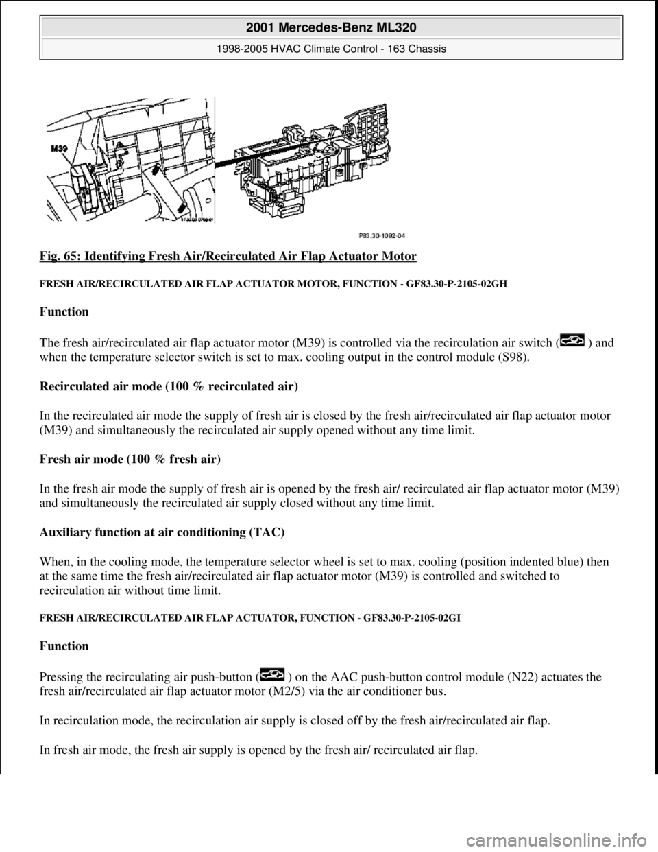
Fig. 65: Identifying Fresh Air/Recirc ulated Air Flap Actuator Motor
FRESH AIR/RECIRCULATED AIR FLAP ACTUATOR MOTO R, FUNCTION - GF83.30-P-2105-02GH
Function
The fresh air/recirculated air flap actuator motor (M39) is controlled via the recirculation air switch ( ) and
when the temperature selector switch is set to max. cooling output in the control module (S98).
Recirculated air mode (100 % recirculated air)
In the recirculated air mode the supply of fresh air is closed by the fresh air/recirculated air flap actuator motor
(M39) and simultaneously the recirculated air supply opened without any time limit.
Fresh air mode (100 % fresh air)
In the fresh air mode the supply of fresh air is opened by th e fresh air/ recirculated air flap actuator motor (M39)
and simultaneously the recirculated air supply closed without any time limit.
Auxiliary function at air conditioning (TAC)
When, in the cooling mode, the temperat ure selector wheel is set to max. cooling (position indented blue) then
at the same time the fres h air/recirculated air flap actuator moto r (M39) is controlled and switched to
recirculation air wi thout time limit.
FRESH AIR/RECIRCUL ATED AIR FLAP ACTUATOR, FU NCTION - GF83.30-P-2105-02GI
Function
Pressing the recirculating air push- button ( ) on the AAC push-button control module (N22) actuates the
fresh air/recirculated air flap actuator motor (M2/5) via the air conditioner bus.
In recirculation mode, the recircul ation air supply is closed off by th e fresh air/recirculated air flap.
In fresh air mode, the fresh air supply is ope ned by the fresh air/ recirculated air flap.
2001 Mercedes-Benz ML320
1998-2005 HVAC Climate Control - 163 Chassis
me
Saturday, October 02, 2010 3:23:15 PMPage 74 © 2006 Mitchell Repair Information Company, LLC.