Page 1130 of 4133
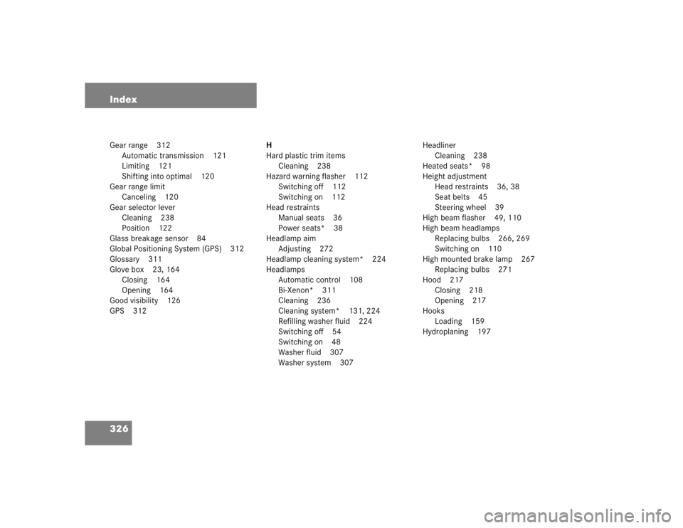
326 IndexGear range 312
Automatic transmission 121
Limiting 121
Shifting into optimal 120
Gear range limit
Canceling 120
Gear selector lever
Cleaning 238
Position 122
Glass breakage sensor 84
Global Positioning System (GPS) 312
Glossary 311
Glove box 23, 164
Closing 164
Opening 164
Good visibility 126
GPS 312H
Hard plastic trim items
Cleaning 238
Hazard warning flasher 112
Switching off 112
Switching on 112
Head restraints
Manual seats 36
Power seats* 38
Headlamp aim
Adjusting 272
Headlamp cleaning system* 224
Headlamps
Automatic control 108
Bi-Xenon* 311
Cleaning 236
Cleaning system* 131, 224
Refilling washer fluid 224
Switching off 54
Switching on 48
Washer fluid 307
Washer system 307Headliner
Cleaning 238
Heated seats* 98
Height adjustment
Head restraints 36, 38
Seat belts 45
Steering wheel 39
High beam flasher 49, 110
High beam headlamps
Replacing bulbs 266, 269
Switching on 110
High mounted brake lamp 267
Replacing bulbs 271
Hood 217
Closing 218
Opening 217
Hooks
Loading 159
Hydroplaning 197
Page 1135 of 4133
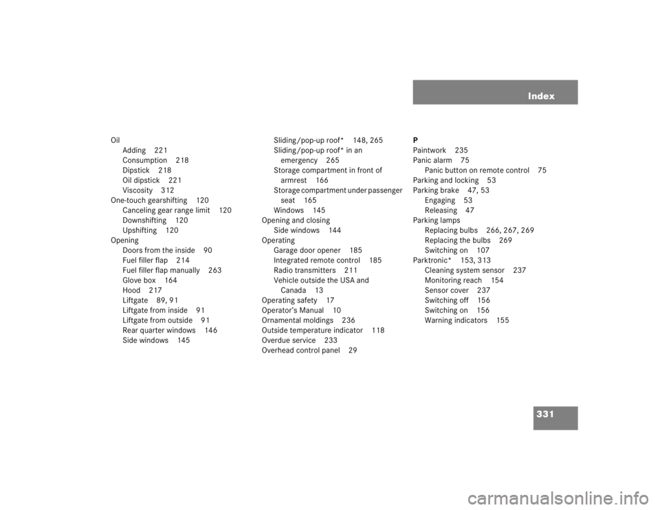
331 Index
Oil
Adding 221
Consumption 218
Dipstick 218
Oil dipstick 221
Viscosity 312
One-touch gearshifting 120
Canceling gear range limit 120
Downshifting 120
Upshifting 120
Opening
Doors from the inside 90
Fuel filler flap 214
Fuel filler flap manually 263
Glove box 164
Hood 217
Liftgate 89, 91
Liftgate from inside 91
Liftgate from outside 91
Rear quarter windows 146
Side windows 145Sliding/pop-up roof* 148, 265
Sliding/pop-up roof* in an
emergency 265
Storage compartment in front of
armrest 166
Storage compartment under passenger
seat 165
Windows 145
Opening and closing
Side windows 144
Operating
Garage door opener 185
Integrated remote control 185
Radio transmitters 211
Vehicle outside the USA and
Canada 13
Operating safety 17
Operator’s Manual 10
Ornamental moldings 236
Outside temperature indicator 118
Overdue service 233
Overhead control panel 29P
Paintwork 235
Panic alarm 75
Panic button on remote control 75
Parking and locking 53
Parking brake 47, 53
Engaging 53
Releasing 47
Parking lamps
Replacing bulbs 266, 267, 269
Replacing the bulbs 269
Switching on 107
Parktronic* 153, 313
Cleaning system sensor 237
Monitoring reach 154
Sensor cover 237
Switching off 156
Switching on 156
Warning indicators 155
Page 1183 of 4133
Fig. 13: Disconnecting Ground Lead From Battery
Courtesy of MERCEDES-BENZ OF NORTH AMERICA.
1.1 - Open engine hood.
2 - Disconnect ground cable of battery. See Fig. 13
.
NOTE: Model Series 163.
NOTE: To protect against unwanted contact of the disconnected ground line (1)
W16/4 insulate cable lug of the ground line.
2001 Mercedes-Benz ML320
1998-03 AUTOMATIC TRANSMISSIONS Complete Transmissions - ML 320 - 722.662
me
Saturday, October 02, 2010 3:15:25 PMPage 14 © 2006 Mitchell Repair Information Company, LLC.
Page 1748 of 4133
Fig. 153: Identifying Headlamp Unit Bulbs Components
REMOVE/INSTALL FOG LAMP BULB - AR82.10-P-1825GH
Remove/install
1Open hood and raise to
vertical positionUp to 31.08.99AR88.40-P-1000GH
As of 01.09.99AR88.40-P-1000GI
2Release cover (1) by
pressing on catch lever (3,
direction of arrow) and
remove
3Remove cover (2)
4Disconnect electrical
connectors (4) for bulbs
5Open retaining clips (5)
for bulbs
6Remove bulbs (E1e1,
E1e2, E1e4) Do not touch bulbs
with bare fingers, use
grease-free, soft cloth.
Installation: Ensure
bulb is correctly installed.
7Install in the reverse order
8Perform function check
2001 Mercedes-Benz ML320
1998-2005 ACCESSORIES & BODY, CAB Electrical System - Body - 163 Chassis
me
Saturday, October 02, 2010 3:30:08 PMPage 253 © 2006 Mitchell Repair Information Company, LLC.
Page 1758 of 4133
REMOVE/INSTALL HEADLAMP UNIT - AR82.10-P-4730GH
MODEL 163.113 /128 /136 /154 /157 /172 /174 /175
Fig. 163: Identifying Headlamp Unit Components
paneling (4)
2Unscrew screw (2) of turn
signal lamp (3) in the
exterior mirror paneling
(4)
3Remove turn signal lamp
(3) from the exterior
mirror paneling (4)
4Install in the reverse order
Remove/Install
1Open engine hood
2Unlock cover (1) at the
clip (arrow A) under the
lamp unit and unhook Installation: Lock
clip again.
3Unscrew screw (2)
4Unscrew nuts (3). Installation: Align
the lamp unit so that the
2001 Mercedes-Benz ML320
1998-2005 ACCESSORIES & BODY, CAB Electrical System - Body - 163 Chassis
me
Saturday, October 02, 2010 3:30:09 PMPage 263 © 2006 Mitchell Repair Information Company, LLC.
Page 2030 of 4133
AR09.41-P-6817MM
Removing and installing charge air cooler
10.11.99
ENGINE
612.963 in MODEL 163.113
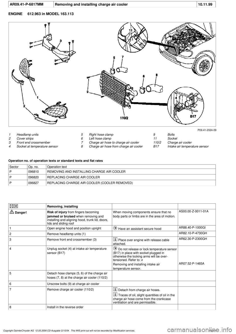
P09.41-2024-09
1
Headlamp units
2
Cover strips
3
Front end crossmember
4
Socket at temperature sensor
9
Bolts
11
Socket
110/2
Charge air cooler
B17
Intake air temperature sensor
5
Right hose clamp
6
Left hose clamp
7
Charge air hose to charge air cooler
8
Charge air hose from charge air cooler
Operation no. of operation texts or standard texts and flat rates
Sector
Op. no.
Operation text
P
096810
REMOVING AND INSTALLING CHARGE AIR COOLER
P
096820
REPLACING CHARGE AIR COOLER
P
096827
REPLACING CHARGE AIR COOLER (COOLER REMOVED)
Removing, installing
Danger!
Risk of injury
from fingers becoming
jammed or bruised
when removing and
installing and aligning hood, trunk lid, doors,
lids and sliding roof
When moving components ensure that no
body parts or limbs are in the area of motion.
AS00.00-Z-0011-01A
1
Open engine hood and position upright
Have an assistant secure hood
AR88.40-P-1000GI
2
Remove headlamp units (1)
AR82.10-P-4730GH
3
Remove front end crossmember (3)
Place over engine with release cable
attached.
AR62.30-P-2300GH
4
Unplug socket (4) at intake air temperature
sensor (B17)
Do not release or lock temperature sensor
(B17) in place with socket plugged in
otherwise the locking arms will be over-
tensioned. Refer to:
#
Removing and installing intake air
temperature sensor.
AR07.52-P-1465A
5
Detach hose clamps (5, 6) of the charge air
hoses (7, 8) at the charge air cooler (110/2)
6
Unscrew bolts (9) at charge air cooler
7
Remove charge air cooler (110/2)
Detach from charge air hoses.
Traces of oil, slight quantities of oil in the
charge air hose come from the crankcase
ventilation and are permissible.
8
Install in the reverse order
Copyright DaimlerChrysler AG 12.05.2006 CD-Ausgabe G/10/04 . This WIS print-out will not be recorde
d by Modification services.
Page 1
Page 2032 of 4133
AR09.41-P-6817MM
Removing and installing charge air cooler
10.11.99
ENGINE
612.963 in MODEL 163.113
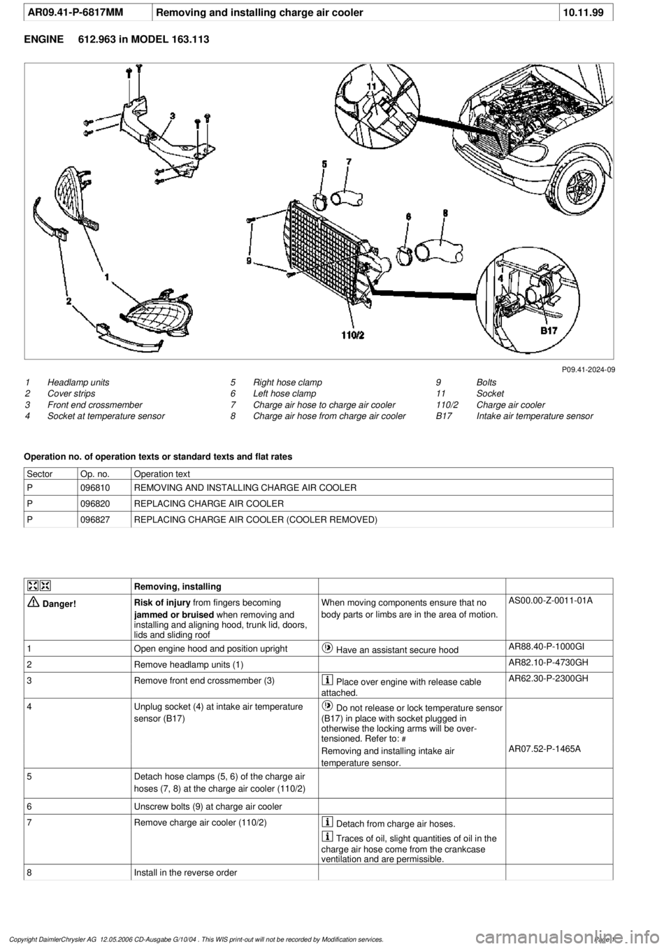
P09.41-2024-09
1
Headlamp units
2
Cover strips
3
Front end crossmember
4
Socket at temperature sensor
9
Bolts
11
Socket
110/2
Charge air cooler
B17
Intake air temperature sensor
5
Right hose clamp
6
Left hose clamp
7
Charge air hose to charge air cooler
8
Charge air hose from charge air cooler
Operation no. of operation texts or standard texts and flat rates
Sector
Op. no.
Operation text
P
096810
REMOVING AND INSTALLING CHARGE AIR COOLER
P
096820
REPLACING CHARGE AIR COOLER
P
096827
REPLACING CHARGE AIR COOLER (COOLER REMOVED)
Removing, installing
Danger!
Risk of injury
from fingers becoming
jammed or bruised
when removing and
installing and aligning hood, trunk lid, doors,
lids and sliding roof
When moving components ensure that no
body parts or limbs are in the area of motion.
AS00.00-Z-0011-01A
1
Open engine hood and position upright
Have an assistant secure hood
AR88.40-P-1000GI
2
Remove headlamp units (1)
AR82.10-P-4730GH
3
Remove front end crossmember (3)
Place over engine with release cable
attached.
AR62.30-P-2300GH
4
Unplug socket (4) at intake air temperature
sensor (B17)
Do not release or lock temperature sensor
(B17) in place with socket plugged in
otherwise the locking arms will be over-
tensioned. Refer to:
#
Removing and installing intake air
temperature sensor.
AR07.52-P-1465A
5
Detach hose clamps (5, 6) of the charge air
hoses (7, 8) at the charge air cooler (110/2)
6
Unscrew bolts (9) at charge air cooler
7
Remove charge air cooler (110/2)
Detach from charge air hoses.
Traces of oil, slight quantities of oil in the
charge air hose come from the crankcase
ventilation and are permissible.
8
Install in the reverse order
Copyright DaimlerChrysler AG 12.05.2006 CD-Ausgabe G/10/04 . This WIS print-out will not be recorde
d by Modification services.
Page 1
Page 2037 of 4133
Fig. 1: Drive Belt Routing
Courtesy of MERCEDES-BENZ OF NORTH AMERICA.
TROUBLE SHOOTING
PRELIMINARY INSPECTION
Verify customer complaint by operating system. Visually inspect for obvious signs of mechanical and electrical
damage. Check generator belt tension and condition. Ensure that battery voltage is within specifications. Inspect
for blown fuses and damaged relays.
Verify ground connection integrity between engine, body, battery and generator. Check for damaged wiring
harnesses and/or switches. Check for a broken or partially broken wire inside insulation, which could cause
system malfunction but prove good in a continuity/voltage check with system disconnected. Ensure any
aftermarket electronic equipment is properly installed. If fault is found, repair as necessary. If no fault is found,
check for conditions that might cause an intermittent situation.
SERVICE PRECAUTIONS
BATTERY DISCONNECT/CONNECT
Disconnect Procedures
1. On vehicles not equipped with TELE AID, go to step 5 . Vehicles equipped with TELE AID, switch
TELE AID into service mode by turning ignition ON.
2. Turn ON telephone and enter code "*#4610#" on handset.
3. Confirm that "No Telematics Service" appears on handset with okay.
4. Turn OFF handset.
5. Turn OFF ignition.
6. Open hood and open snap fasteners (1) on dust filter housing. See Fig. 2
.
7. Remove dust filter housing (2) exposing battery.
8. If not using quiescent current retention unit, go to step 14 . If using quiescent current retention unit, go to
next step.
9. Connect quiescent current retention unit by switching on quiescent current retention unit (7) and then first
connecting positive terminal (8) and negative terminal (9) of retention unit to positive cable and battery
ground (W10). See Fig. 3
.
10. On vehicles equipped with TELE AID, remove luggage compartment cargo anchoring lugs and remove
floor paneling.
11. Remove screws (1). See Fig. 4
.
12. Dismantle cover from TELE AID control module (A35/8).
13. Disconnect connection coupling for back up battery and remove back up battery.
14. Disconnect ne
gative battery cable (1) and insulate terminal. See Fig. 5. NOTE: Numbers and letters in text refer to numbers and letters in figures.
2001 Mercedes-Benz ML320
2001-04 STARTING & CHARGING SYSTEMS Generators & Regulators - 163 Chassis
me
Saturday, October 02, 2010 3:20:31 PMPage 3 © 2006 Mitchell Repair Information Company, LLC.