1997 MERCEDES-BENZ ML500 open hood
[x] Cancel search: open hoodPage 3195 of 4133
AR88.40-P-3020GH
Adjust engine hood
8.4.99
MODEL
163.113 /128 /136 /154 /157 /172 /174 /175
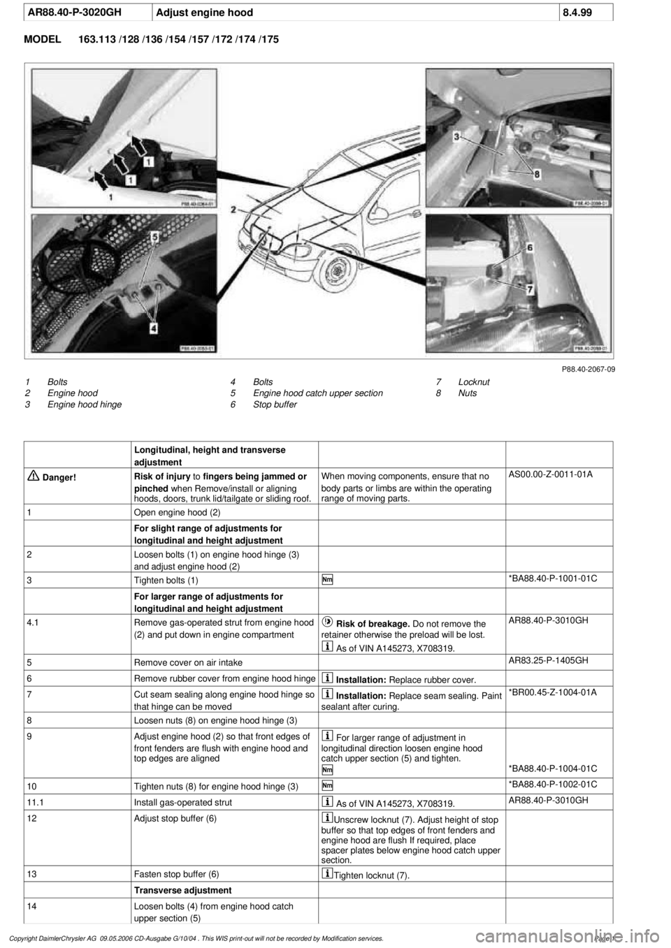
P88.40-2067-09
1
Bolts
2
Engine hood
3
Engine hood hinge
7
Locknut
8
Nuts
4
Bolts
5
Engine hood catch upper section
6
Stop buffer
Longitudinal, height and transverse
adjustment
Danger!
Risk of injury
to
fingers being jammed or
pinched
when Remove/install or aligning
hoods, doors, trunk lid/tailgate or sliding roof.
When moving components, ensure that no
body parts or limbs are within the operating
range of moving parts.
AS00.00-Z-0011-01A
1
Open engine hood (2)
For slight range of adjustments for
longitudinal and height adjustment
2
Loosen bolts (1) on engine hood hinge (3)
and adjust engine hood (2)
3
Tighten bolts (1)
*BA88.40-P-1001-01C
For larger range of adjustments for
longitudinal and height adjustment
4.1
Remove gas-operated strut from engine hood
(2) and put down in engine compartment
Risk of breakage. Do not remove the
retainer otherwise the preload will be lost.
AR88.40-P-3010GH
As of VIN A145273, X708319.
5
Remove cover on air intake
AR83.25-P-1405GH
6
Remove rubber cover from engine hood hinge
Installation:
Replace rubber cover.
7
Cut seam sealing along engine hood hinge so
that hinge can be moved
Installation:
Replace seam sealing. Paint
sealant after curing.
*BR00.45-Z-1004-01A
8
Loosen nuts (8) on engine hood hinge (3)
9
Adjust engine hood (2) so that front edges of
front fenders are flush with engine hood and
top edges are aligned
For larger range of adjustment in
longitudinal direction loosen engine hood
catch upper section (5) and tighten.
*BA88.40-P-1004-01C
10
Tighten nuts (8) for engine hood hinge (3)
*BA88.40-P-1002-01C
11.1
Install gas-operated strut
As of VIN A145273, X708319.
AR88.40-P-3010GH
12
Adjust stop buffer (6)
Unscrew locknut (7). Adjust height of stop
buffer so that top edges of front fenders and
engine hood are flush If required, place
spacer plates below engine hood catch upper
section.
13
Fasten stop buffer (6)
Tighten locknut (7).
Transverse adjustment
14
Loosen bolts (4) from engine hood catch
upper section (5)
Copyright DaimlerChrysler AG 09.05.2006 CD-Ausgabe G/10/04 . This WIS print-out will not be recorde
d by Modification services.
Page 1
Page 3197 of 4133
AR88.40-P-3100GH
Remove/install control cable for engine hood
5.5.00
MODEL
163.113 /128 /136 /154 /157 /172 /174 /175
P88.40-2140-06
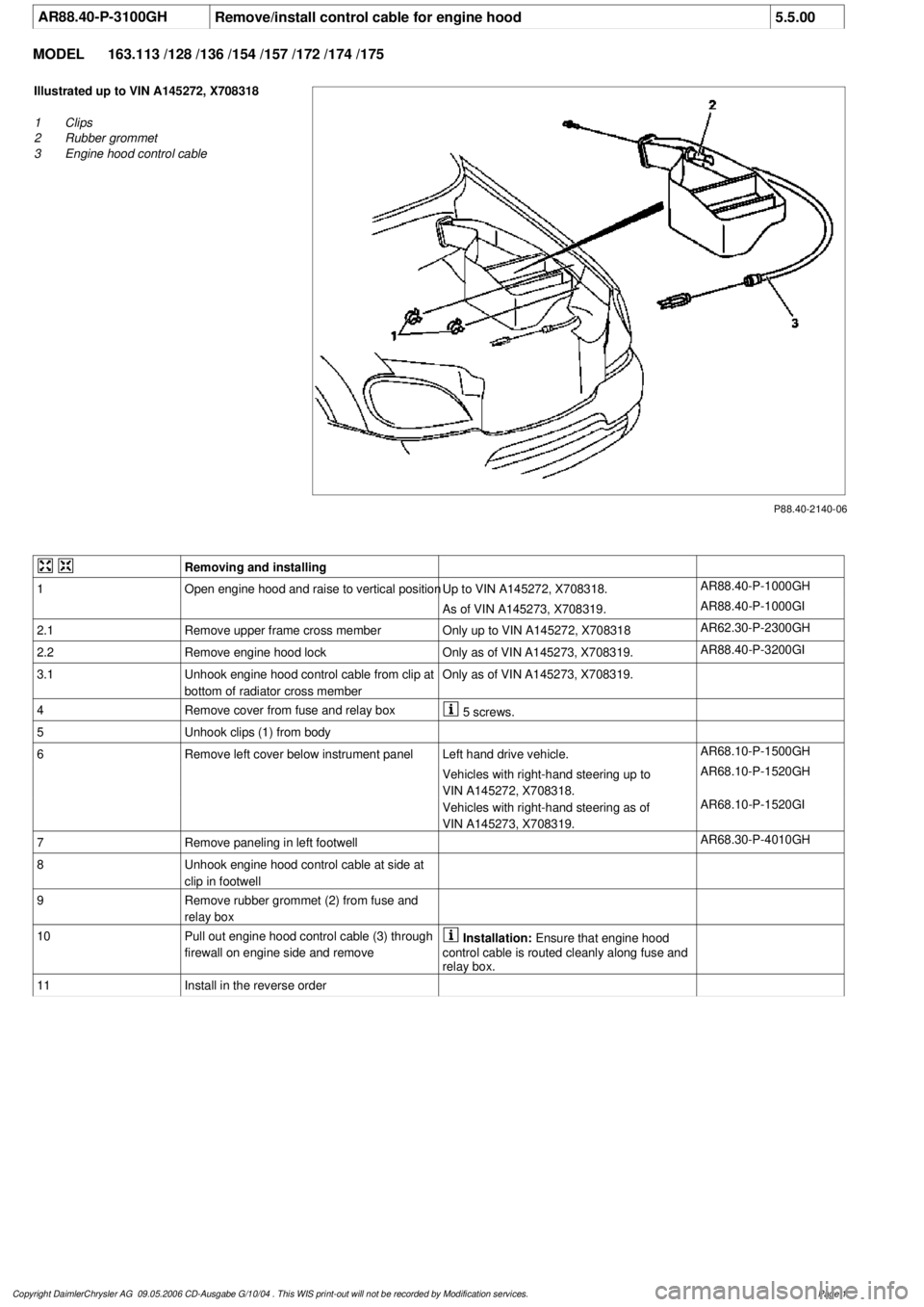
Illustrated up to VIN A145272, X708318
1
Clips
2
Rubber grommet
3
Engine hood control cable
Removing and installing
1
Open engine hood and raise to vertical position
Up to VIN A145272, X708318.
AR88.40-P-1000GH
As of VIN A145273, X708319.
AR88.40-P-1000GI
2.1
Remove upper frame cross member
Only up to VIN A145272, X708318
AR62.30-P-2300GH
2.2Remove engine hood lock
Only as of VIN A145273, X708319.
AR88.40-P-3200GI
3.1
Unhook engine hood control cable from clip at
bottom of radiator cross member
Only as of VIN A145273, X708319.
4
Remove cover from fuse and relay box
5 screws.
5
Unhook clips (1) from body
6
Remove left cover below instrument panel
Left hand drive vehicle.
AR68.10-P-1500GH
Vehicles with right-hand steering up to
VIN A145272, X708318.
AR68.10-P-1520GH
Vehicles with right-hand steering as of
VIN A145273, X708319.
AR68.10-P-1520GI
7
Remove paneling in left footwell
AR68.30-P-4010GH
8
Unhook engine hood control cable at side at
clip in footwell
9
Remove rubber grommet (2) from fuse and
relay box
10
Pull out engine hood control cable (3) through
firewall on engine side and remove
Installation:
Ensure that engine hood
control cable is routed cleanly along fuse and
relay box.
11
Install in the reverse order
Copyright DaimlerChrysler AG 09.05.2006 CD-Ausgabe G/10/04 . This WIS print-out will not be recorde
d by Modification services.
Page 1
Page 3199 of 4133
AR88.40-P-3060GH
Remove/install engine hood hinge
16.4.97
MODEL
163.113 /128 /136 /154 /157 /172 /174 /175
P88.40-0365-01
P88.40-0364-01
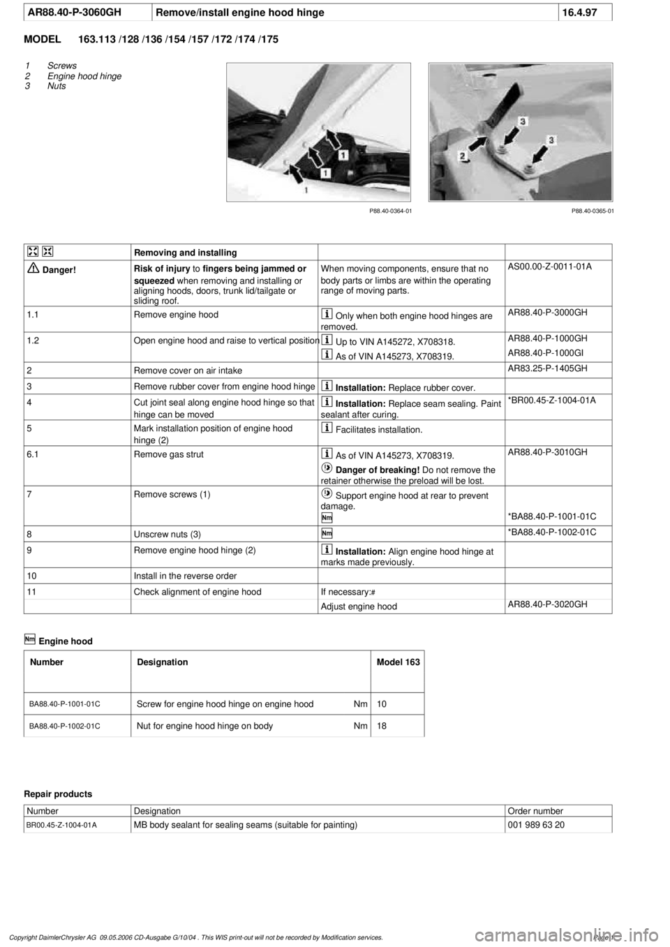
1
Screws
2
Engine hood hinge
3
Nuts
Removing and installing
Danger!
Risk of injury
to
fingers being jammed or
squeezed
when removing and installing or
aligning hoods, doors, trunk lid/tailgate or
sliding roof.
When moving components, ensure that no
body parts or limbs are within the operating
range of moving parts.
AS00.00-Z-0011-01A
1.1
Remove engine hood
Only when both engine hood hinges are
removed.
AR88.40-P-3000GH
1.2
Open engine hood and raise to vertical position
Up to VIN A145272, X708318.
AR88.40-P-1000GH
As of VIN A145273, X708319.
AR88.40-P-1000GI
2
Remove cover on air intake
AR83.25-P-1405GH
3
Remove rubber cover from engine hood hinge
Installation:
Replace rubber cover.
4
Cut joint seal along engine hood hinge so that
hinge can be moved
Installation:
Replace seam sealing. Paint
sealant after curing.
*BR00.45-Z-1004-01A
5
Mark installation position of engine hood
hinge (2)
Facilitates installation.
6.1
Remove gas strut
As of VIN A145273, X708319.
AR88.40-P-3010GH
Danger of breaking!
Do not remove the
retainer otherwise the preload will be lost.
7
Remove screws (1)
Support engine hood at rear to prevent
damage.
*BA88.40-P-1001-01C
8
Unscrew nuts (3)
*BA88.40-P-1002-01C
9
Remove engine hood hinge (2)
Installation:
Align engine hood hinge at
marks made previously.
10
Install in the reverse order
11
Check alignment of engine hood
If necessary:
#
Adjust engine hood
AR88.40-P-3020GH
Engine hood
Number
Designation
Model 163
BA88.40-P-1001-01C
Screw for engine hood hinge on engine hood
Nm
10
BA88.40-P-1002-01C
Nut for engine hood hinge on body
Nm
18
Repair products
Number
Designation
Order number
BR00.45-Z-1004-01A
MB body sealant for sealing seams (suitable for painting)
001 989 63 20
Copyright DaimlerChrysler AG 09.05.2006 CD-Ausgabe G/10/04 . This WIS print-out will not be recorde
d by Modification services.
Page 1
Page 3206 of 4133
AR88.40-P-3200GI
Remove/install engine hood lock
9.4.99
MODEL
163.136 /154 /172 #A as of 145273,
163.136 /154 /172 #X as of 708319,
163.113 /128 /157 /174 /175
P88.40-2058-06
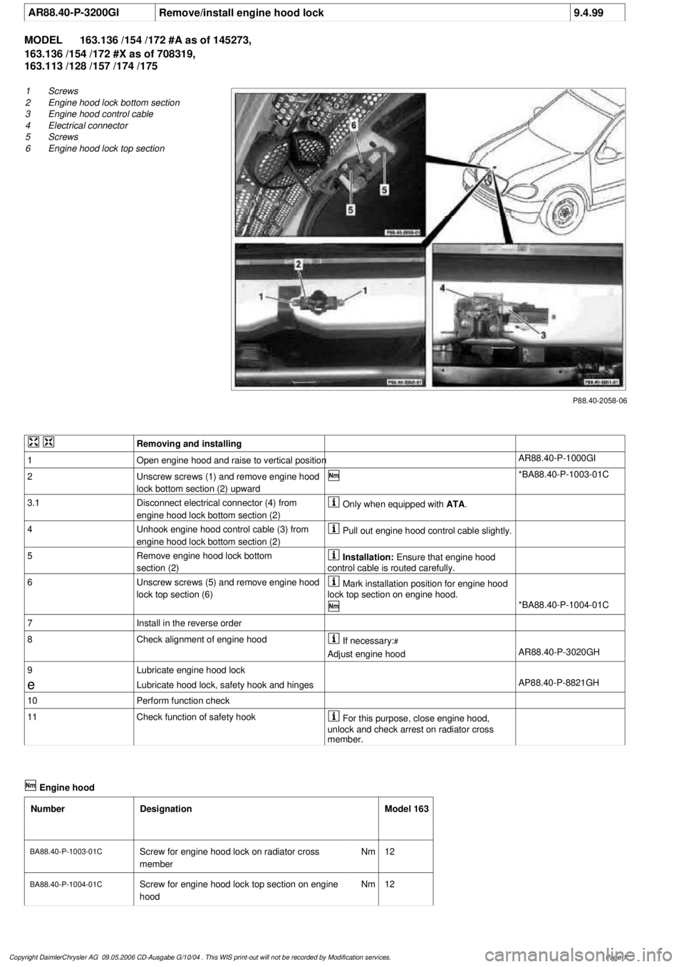
1
Screws
2
Engine hood lock bottom section
3
Engine hood control cable
4
Electrical connector
5
Screws
6
Engine hood lock top section
Removing and installing
1
Open engine hood and raise to vertical position
AR88.40-P-1000GI
2
Unscrew screws (1) and remove engine hood
lock bottom section (2) upward
*BA88.40-P-1003-01C
3.1
Disconnect electrical connector (4) from
engine hood lock bottom section (2)
Only when equipped with
ATA
.
4
Unhook engine hood control cable (3) from
engine hood lock bottom section (2)
Pull out engine hood control cable slightly.
5
Remove engine hood lock bottom
section (2)
Installation:
Ensure that engine hood
control cable is routed carefully.
6
Unscrew screws (5) and remove engine hood
lock top section (6)
Mark installation position for engine hood
lock top section on engine hood.
*BA88.40-P-1004-01C
7
Install in the reverse order
8
Check alignment of engine hood
If necessary:
#
Adjust engine hood
AR88.40-P-3020GH
9
Lubricate engine hood lock
e
Lubricate hood lock, safety hook and hinges
AP88.40-P-8821GH
10
Perform function check
11
Check function of safety hook
For this purpose, close engine hood,
unlock and check arrest on radiator cross
member.
Engine hood
Number
Designation
Model 163
BA88.40-P-1003-01C
Screw for engine hood lock on radiator cross
member
Nm
12
BA88.40-P-1004-01C
Screw for engine hood lock top section on engine
hood
Nm
12
Copyright DaimlerChrysler AG 09.05.2006 CD-Ausgabe G/10/04 . This WIS print-out will not be recorde
d by Modification services.
Page 1
Page 3208 of 4133
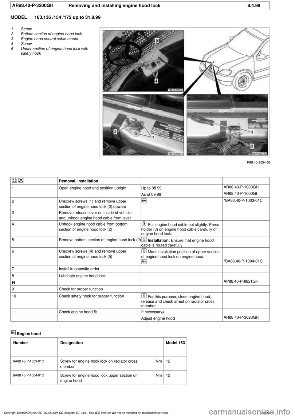
AR88.40-P-3200GH
Removing and installing engine hood lock
8.4.99
MODEL
163.136 /154 /172 up to 31.8.99
P88.40-2054-06
1
Screw
2
Bottom section of engine hood lock
3
Engine hood control cable mount
4
Screw
5
Upper section of engine hood lock with
safety hook
Removal, installation
1
Open engine hood and position upright
Up to 08.99
AR88.40-P-1000GH
As of 09.99
AR88.40-P-1000GI
2
Unscrew screws (1) and remove upper
section of engine hood lock (2) upward
*BA88.40-P-1003-01C
3
Remove release lever on inside of vehicle
and unhook engine hood cable from lever
4
Unhook engine hood cable from bottom
section of engine hood lock (2)
Pull engine hood cable out slightly. Press
holder (3) on engine hood cable carefully off
engine hood lock.
5
Remove bottom section of engine hood lock (2)
Installation:
Ensure that engine hood
cable is routed carefully.
6
Unscrew screws (4) and remove upper
section of engine hood lock (5)
Mark installation position of upper section
of engine hood lock on engine hood.
*BA88.40-P-1004-01C
7
Install in opposite order
8
Lubricate engine hood lock
e
AP88.40-P-8821GH
9
Check for proper function
10
Check safety hook for proper function
For this purpose, close engine hood,
release and check arrest on radiator cross
member
11
Check engine hood fit
If necessary
#
Adjust engine hood
AR88.40-P-3020GH
Engine hood
Number
Designation
Model 163
BA88.40-P-1003-01C
Screw for engine hook lock on radiator cross
member
Nm
12
BA88.40-P-1004-01C
Screw for engine hood lock upper section on
engine hood
Nm
12
Copyright DaimlerChrysler AG 09.05.2006 CD-Ausgabe G/10/04 . This WIS print-out will not be recorde
d by Modification services.
Page 1
Page 3209 of 4133
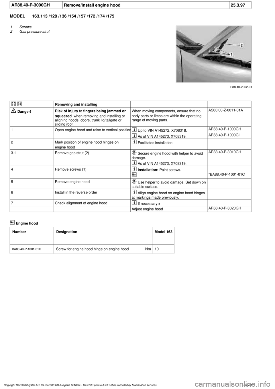
AR88.40-P-3000GH
Remove/install engine hood
25.3.97
MODEL
163.113 /128 /136 /154 /157 /172 /174 /175
P88.40-2062-01
1
Screws
2
Gas pressure strut
Removing and installing
Danger!
Risk of injury
to
fingers being jammed or
squeezed
when removing and installing or
aligning hoods, doors, trunk lid/tailgate or
sliding roof.
When moving components, ensure that no
body parts or limbs are within the operating
range of moving parts.
AS00.00-Z-0011-01A
1
Open engine hood and raise to vertical position
Up to VIN A145272, X708318.
AR88.40-P-1000GH
As of VIN A145273, X708319.
AR88.40-P-1000GI
2
Mark position of engine hood hinges on
engine hood
Facilitates installation.
3.1
Remove gas strut (2)
Secure engine hood with helper to avoid
damage.
AR88.40-P-3010GH
As of VIN A145273, X708319.
4
Remove screws (1)
Installation:
Paint screws.
*BA88.40-P-1001-01C
5
Remove engine hood
Use helper to avoid damage. Set down on
suitable surface.
6
Install in the reverse order
Align engine hood on engine hood hinges
at markings made previously.
7
Check alignment of engine hood
If necessary:
#
Adjust engine hood
AR88.40-P-3020GH
Engine hood
Number
Designation
Model 163
BA88.40-P-1001-01C
Screw for engine hood hinge on engine hood
Nm
10
Copyright DaimlerChrysler AG 09.05.2006 CD-Ausgabe G/10/04 . This WIS print-out will not be recorde
d by Modification services.
Page 1
Page 3211 of 4133
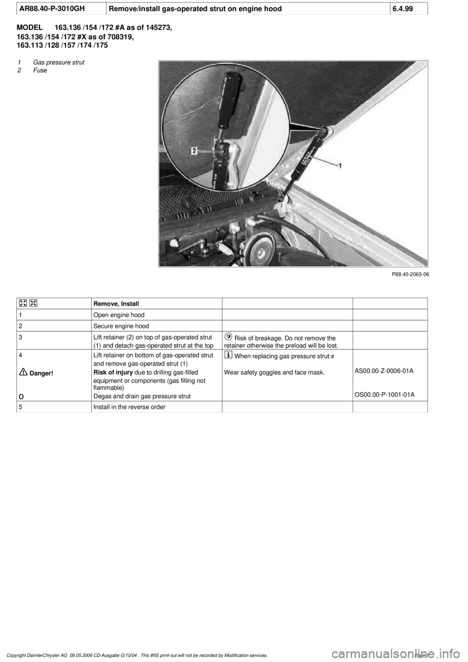
AR88.40-P-3010GH
Remove/install gas-operated strut on engine hood
6.4.99
MODEL
163.136 /154 /172 #A as of 145273,
163.136 /154 /172 #X as of 708319,
163.113 /128 /157 /174 /175
P88.40-2063-06
1
Gas pressure strut
2
Fuse
Remove, Install
1
Open engine hood
2
Secure engine hood
3
Lift retainer (2) on top of gas-operated strut
(1) and detach gas-operated strut at the top
Risk of breakage. Do not remove the
retainer otherwise the preload will be lost.
4
Lift retainer on bottom of gas-operated strut
and remove gas-operated strut (1)
When replacing gas pressure strut:
#
Danger!
Risk of injury
due to drilling gas-filled
equipment or components (gas filling not
flammable)
Wear safety goggles and face mask.
AS00.00-Z-0006-01A
o
Degas and drain gas pressure strut
OS00.00-P-1001-01A
5
Install in the reverse order
Copyright DaimlerChrysler AG 09.05.2006 CD-Ausgabe G/10/04 . This WIS print-out will not be recorde
d by Modification services.
Page 1
Page 3236 of 4133
Fig. 9: Replacing Intake Air Dust Filter
Courtesy of MERCEDES-BENZ OF NORTH AMERICA.
RECEIVER-DRIER
Removal & Installation
1. Discharge A/C system, using approved refrigerant recovery/recycling equipment. Remove headlight
units. Remove headlight units. Remove upper frame crossmember, release hood release control cable and
remove crossmember. See Fig. 6
.
2. Remove bolts from receiver-drier refrigerant lines. See Fig. 5
. Disconnect refrigerant lines from receiver-
drier. Plug exposed openings to protect A/C system from debris and moisture. Discard "O" rings. Loosen
receiver-drier clamp bolt. Remove receiver-drier. To install, reverse removal procedure.
3. When installing a new receiver-drier, add 0.34 ounce of NEW refrigerant oil to receiver-drier. Use NEW
"O" rings. Tighten refrigerant line bolts to specification. See TORQUE SPECIFICATIONS
.
TORQUE SPECIFICATIONS
TORQUE SPECIFICATIONS
WIRING DIAGRAMS
ApplicationFt. Lbs. (N.m)
Compressor Mounting Bolts15 (20)
Refrigerant Line-To-Compressor Bolt15 (20)
Refrigerant Line-To-Condenser Bolt15 (20)
Steering Column Bolt15 (20)
Steering Column Nut13 (18)
INCH Lbs. (N.m)
Expansion Valve Self-Locking Nut89 (10)
Refrigerant Line-To-Receiver-Drier Bolt89 (10)
2001 Mercedes-Benz ML320
2000-01 MANUAL A/C-HEATER SYSTEMS ML 320, ML 430 & ML 55
me
Saturday, October 02, 2010 3:25:10 PMPage 25 © 2006 Mitchell Repair Information Company, LLC.