Page 1054 of 4133
250 Practical hintsWhat to do if …Warning!
G
Driving when your engine is badly overheat-
ed can cause some fluids which may have
leaked into the engine compartment to
catch fire. You could be seriously burned.
Steam from an overheated engine can cause
serious burns and can occur just by opening
the engine hood. Stay away from the engine
if you see or hear steam coming from it.
Turn off the engine, get out of the vehicle
and do not stand near the vehicle until the
engine has cooled down.Warning!
G
Do not spill antifreeze on hot engine parts.
Antifreeze contains ethylene glycol which
may burn if it comes into contact with hot
engine parts. You can be seriously burned.
!Do not ignore the coolant warning
lamps. Extended driving with the sym-
bol displayed may cause serious engine
damage not covered by the
Mercedes-Benz Limited Warranty.
Do not drive without sufficient amount
of coolant. The engine will overheat,
causing major engine damage.
Page 1072 of 4133
268 Practical hintsReplacing bulbsReplacing bulbs for front lamps
Replacing low beam bulbs
1Low beam halogen or Bi-Xenon* head-
lamp cover with locking tab2Electrical connector
Bi-Xenon* headlampHalogen headlamp
�
Switch off the lights.
�
Open the hood (
�page 217).
�
Push down tab at top end of cover1
and remove.
�
Pull electrical connector2 off.
�
Unclip the retainer springs and take out
the bulb.
�
Insert the new bulb so that the base lo-
cates in the recess on the holder.
�
Clip the retainer springs.
�
Plug the connector2 onto the bulb.
�
Align headlamp cover and click into
place.
Warning!
G
Do not remove the cover
1
for the
Bi-Xenon headlamp. Because of high voltage
in xenon lamps, it is dangerous to replace
the bulb or repair the lamp and its compo-
nents. We recommend that you have such
work done by a qualified technician.
Page 1073 of 4133
269 Practical hints
Replacing bulbs
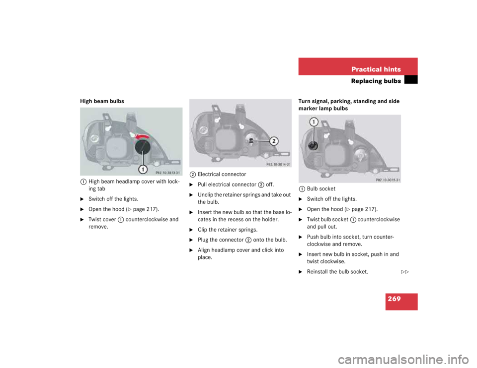
High beam bulbs
1High beam headlamp cover with lock-
ing tab�
Switch off the lights.
�
Open the hood (
�page 217).
�
Twist cover1 counterclockwise and
remove.2Electrical connector
�
Pull electrical connector2 off.
�
Unclip the retainer springs and take out
the bulb.
�
Insert the new bulb so that the base lo-
cates in the recess on the holder.
�
Clip the retainer springs.
�
Plug the connector2 onto the bulb.
�
Align headlamp cover and click into
place.Turn signal, parking, standing and side
marker lamp bulbs
1Bulb socket
�
Switch off the lights.
�
Open the hood (
�page 217).
�
Twist bulb socket1 counterclockwise
and pull out.
�
Push bulb into socket, turn counter-
clockwise and remove.
�
Insert new bulb in socket, push in and
twist clockwise.
�
Reinstall the bulb socket.
��
Page 1076 of 4133

272 Practical hintsReplacing bulbs�
Insert reflector from the left so that it
engages on the right.
�
Position tabs of cover in slots and rein-
stall cover until properly seated.
Adjusting headlamp aim
VVertical centerline
HHeadlamp mounting high, measured
from the centerCorrect headlamp adjustment is extremely
important. To check and readjust a head-
lamp, follow the steps described:
�
Park the vehicle on a level surface
25 feet (7.6 m) from a vertical test
screen or wall.
�
Switch the headlamps on
(�page 110).
If the beam does not show a beam pattern
as indicated in the figure left, then follow
the steps below:
�
Open hood (
�page 217).
2Headlamp vertical adjustment screw
3Headlamp vertical adjustment screw
�
Always turn adjustment screws2
and3 simultaneously for vertical ad-
justment until the headlamp is adjust-
ed as shown1. Turn clockwise for
upward movement and counterclock-
wise for downward movement.
Graduations:
screw2: 0.50° pitch
screw3: 0.67° pitch
The left and right headlamps must be ad-
justed individually.
iHigh beam adjustments simultaneous-
ly aim the low beam.
Vehicle should have a normal trunk
load.
iIf it is not possible to obtain a proper
headlamp adjustment, have the system
checked at your authorized
Mercedes-Benz Light Truck Center.
��
Page 1077 of 4133

273 Practical hints
Replacing wiper blades
�Replacing wiper blades
Removing�
Fold the wiper arm forward.
�
Turn wiper blade at a right angle to wip-
er arm.
1Wiper blade
2Safety tab
�
Press safety tab down2.
�
Push wiper blade downward1 and re-
move.
Installing�
Slide the wiper blade into end of wiper
arm until it locks in place.
�
Fold the wiper arm back to rest on the
windshield. Make sure you hold onto
the wiper when folding the wiper arm
back.
Warning!
G
For safety reasons, remove key from steer-
ing lock before replacing a wiper blade. Oth-
erwise the motor could suddenly turn on and
cause injury.
!Never open the hood when the wiper
arms are folded forward.
Hold on to the wiper when folding the
wiper arm back. If released, the force
of the impact from the tensioning
spring could crack the windshield.
Do not allow the wiper arms to contact
the windshield glass without a wiper
blade inserted.
Make certain that the wiper blades are
properly installed. Improperly installed
wiper blades may cause windshield
damage.
For your convenience, we recommend
that you have this work carried out by
an authorized Mercedes-Benz Center.
Page 1083 of 4133

279 Practical hints
Battery
Disconnecting the battery�
Depress parking brake firmly or move
gear selector lever to positionP.
�
Turn off all electrical consumers.
�
Remove key from the steering lock.
�
Open the hood (
�page 217).
�
Disconnect the battery negative lead.
�
Remove the cover from the positive ter-
minal.
�
Disconnect the battery positive lead.
Removing the batteries�
Remove the screw securing the bat-
tery.
�
Remove the battery support and brack-
et. Take out the battery.
Charging and reinstalling batteries�
Charge battery in accordance with the
instructions of the battery charger
manufacturer.
�
Reinstall the charged battery. Follow
the previously described steps in re-
verse order.
Reconnecting the batteries�
Turn off all electrical consumers.
�
Connect the positive lead and fasten its
cover.
�
Connect the negative lead.
Warning!
G
With a disconnected battery�
you will no longer be able to turn the key
in the steering lock
�
the gear selector lever will remain
locked in positionP
Warning!
G
Never charge a battery while still installed in
the vehicle. Gases may escape during charg-
ing and cause explosions that may result in
paint damage, corrosion or personal injury.
!Never invert the terminal connections!!The battery, its filler caps and the vent
tube must always be securely installed
when the vehicle is in operation.
Page 1086 of 4133

282 Practical hintsJump startingThe battery is located on the right side of
the engine compartment.�
Make sure the two vehicles do not
touch.
�
Turn off all electrical consumers.
�
Apply parking brake.
�
Shift gear selector lever to positionP.
�
Open the hood.
�
Connect positive terminals1 and4
of the batteries with the jumper cable.
Clamp cable to positive terminal4 of
charged battery first.1Positive terminal of discharged battery
2Negative terminal of discharged
battery
3Negative terminal of charged battery
4Positive terminal of charged battery
�
Start engine of the vehicle with the
charged battery and run at idle speed.
�
Connect negative terminals2 and3
of the batteries with the jumper cable.
Clamp cable to negative terminal3 of
charged battery first.
�
Start the engine of the disabled vehi-
cle.
Now you can turn on the electrical
consumers. Do not turn on the lights under
any circumstances.
�
Remove the jumper cables first from
the negative terminals2 and3 and
then from positive terminals1
and4.
You can now turn on the lights.
�
Have the battery checked at the
nearest authorized Mercedes-Benz
Light Truck Center.
Warning!
G
Keep flames or sparks away from battery.
Do not smoke.
Observe all safety instructions and precau-
tions when handling automotive batteries
(�page 223).
!Never invert the terminal connections.
!Do not tow-start the vehicle.
Page 1128 of 4133
 124
Emergency operations
Closing sliding/pop-up roof* 265
Locking the vehicle 262
Ope")
324 IndexEmergency calls
Initiating an emergency call 175
With Tele Aid* 173
Emergency operation (Limp Home
Mode) 124
Emergency operations
Closing sliding/pop-up roof* 265
Locking the vehicle 262
Opening sliding/pop-up roof* 265
Remote door unlock 179
Unlocking the vehicle 261
Emergency tensioning device see
ETD 67, 312
Emission control 212
Emission control label 292
Engine
Starting 46
Technical data 294
Turning off 54
Engine cleaning 236Engine compartment
Fuse box in 287
Hood 217
Engine malfunction indicator lamp 25,
248
Engine number 311
Engine oil 218, 302
Adding 221
Additives 302
Checking level 218
Consumption 218
Messages in display 219
Oil dipstick 221
Viscosity 312
Enlarged cargo area 99
Error
Display messages 256ESP 25, 80, 312
LOW RANGE mode 81
Malfunction indicator lamp 245, 246,
247
Switching off 81
Switching on 82
Synchronizing 246
Warning lamp 245, 246, 247, 251
ETD 312
Safety guidelines 62
ETD (Emergency tensioning device) 67
Exterior mirrors
Folding 128
Exterior rear view mirrors 40
Adjusting 40
Folding electrically 128