1997 MERCEDES-BENZ ML500 warning
[x] Cancel search: warningPage 2035 of 4133
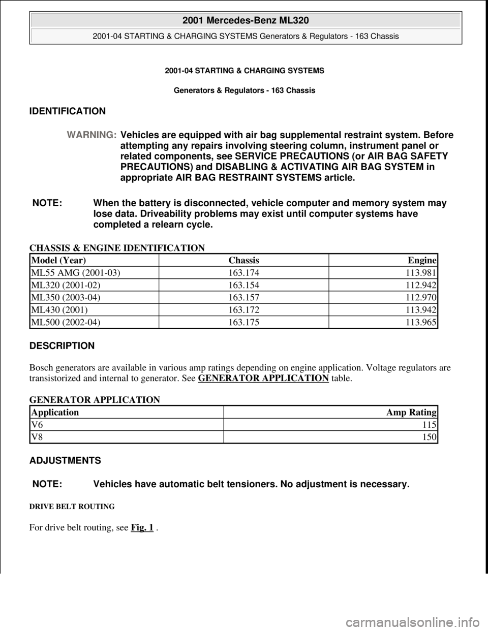
2001-04 STARTING & CHARGING SYSTEMS
Generators & Regulators - 163 Chassis
IDENTIFICATION
CHASSIS & ENGINE IDENTIFICATION
DESCRIPTION
Bosch generators are available in various amp ratings depending on engine application. Voltage regulators are
transistorized and internal to generator. See GENERATOR APPLICATION
table.
GENERATOR APPLICATION
ADJUSTMENTS
DRIVE BELT ROUTING
For drive belt routing, see Fig. 1 . WARNING:Vehicles are equipped with air bag supplemental restraint system. Before
attempting any repairs involving steering column, instrument panel or
related components, see SERVICE PRECAUTIONS (or AIR BAG SAFETY
PRECAUTIONS) and DISABLING & ACTIVATING AIR BAG SYSTEM in
appropriate AIR BAG RESTRAINT SYSTEMS article.
NOTE: When the battery is disconnected, vehicle computer and memory system may
lose data. Driveability problems may exist until computer systems have
completed a relearn cycle.
Model (Year)ChassisEngine
ML55 AMG (2001-03)163.174113.981
ML320 (2001-02)163.154112.942
ML350 (2003-04)163.157112.970
ML430 (2001)163.172113.942
ML500 (2002-04)163.175113.965
ApplicationAmp Rating
V6115
V8150
NOTE: Vehicles have automatic belt tensioners. No adjustment is necessary.
2001 Mercedes-Benz ML320
2001-04 STARTING & CHARGING SYSTEMS Generators & Regulators - 163 Chassis
2001 Mercedes-Benz ML320
2001-04 STARTING & CHARGING SYSTEMS Generators & Regulators - 163 Chassis
me
Saturday, October 02, 2010 3:20:31 PMPage 1 © 2006 Mitchell Repair Information Company, LLC.
me
Saturday, October 02, 2010 3:20:35 PMPage 1 © 2006 Mitchell Repair Information Company, LLC.
Page 2048 of 4133

Fig. 8: Connecting Hand Held Tester Scan Tool To OBD-II Data Link Connector
Courtesy of MERCEDES-BENZ OF NORTH AMERICA.
ON-VEHICLE TESTING
WIRING CONTINUITY
1. Connect voltmeter between generator B+ terminal and ground. Voltmeter should indicate battery voltage.
If battery voltage is not indicated, check battery and check wiring between generator and battery for
corrosion, loose terminals, etc.
2. Turn ignition on and ensure instrument cluster charge indicator light (battery symbol) comes on. If light
does not come on, check wiring between generator and warning light, including indicator bulb.
GENERATOR OUTPUT
1. Ensure connections at battery and generator are clean and tight. Ensure generator, engine and body are
properly grounded. Ensure generator drive belt is properly adjusted and in good condition.
2. Connect load tester/ammeter as per tester manufacturer's instructions. Connect voltmeter leads to battery
terminals. See Fig. 9
. Start engine and run at 2200 RPM for V6 or 2500 RPM for V8. Adjust load tester
to obtain maximum generator output. DO NOT allow voltage to drop to less than 12.7 volts.
3. Maximum generator output should be within a few amps of generator rated output stamped on generator.
If output is not within a few amps of generator rated output, check generator diodes. See DIODE TEST
.
Replace
generator as necessary.
2001 Mercedes-Benz ML320
2001-04 STARTING & CHARGING SYSTEMS Generators & Regulators - 163 Chassis
me
Saturday, October 02, 2010 3:20:32 PMPage 14 © 2006 Mitchell Repair Information Company, LLC.
Page 2106 of 4133

AD54.30-P-3000-03A
Display instruments/multi-function display
function check IC
Display
instruments
The display instruments must indicate according to operating
conditions.
Phototransistor (models 202, 208, 210)
Point a beam of light at the phototransistor with a pocket lamp, the
display illumination of the LCD displays (outside temperature, trip
odometer, total mileage recorder and electronic clock) must get
brighter.
Instrument cluster with multi-function display
If there are malfunctions (e.g. brake linings worn, coolant level too
low, exterior lamp failure etc.) or system faults (anti-lock brake
system faulty, supplemental restraint system faulty) the warning
display with warning information is inserted in place of outside
temperature, odometer, total mileage recorder and electronic clock.
The warning information is displayed in yellow or red depending on
the fault and a warning tone also sounds.
Copyright DaimlerChrysler AG 05.06.2006 CD-Ausgabe G/10/04 . This WIS print-out will not be recorde
d by Modification services.
Page 1
Page 2184 of 4133
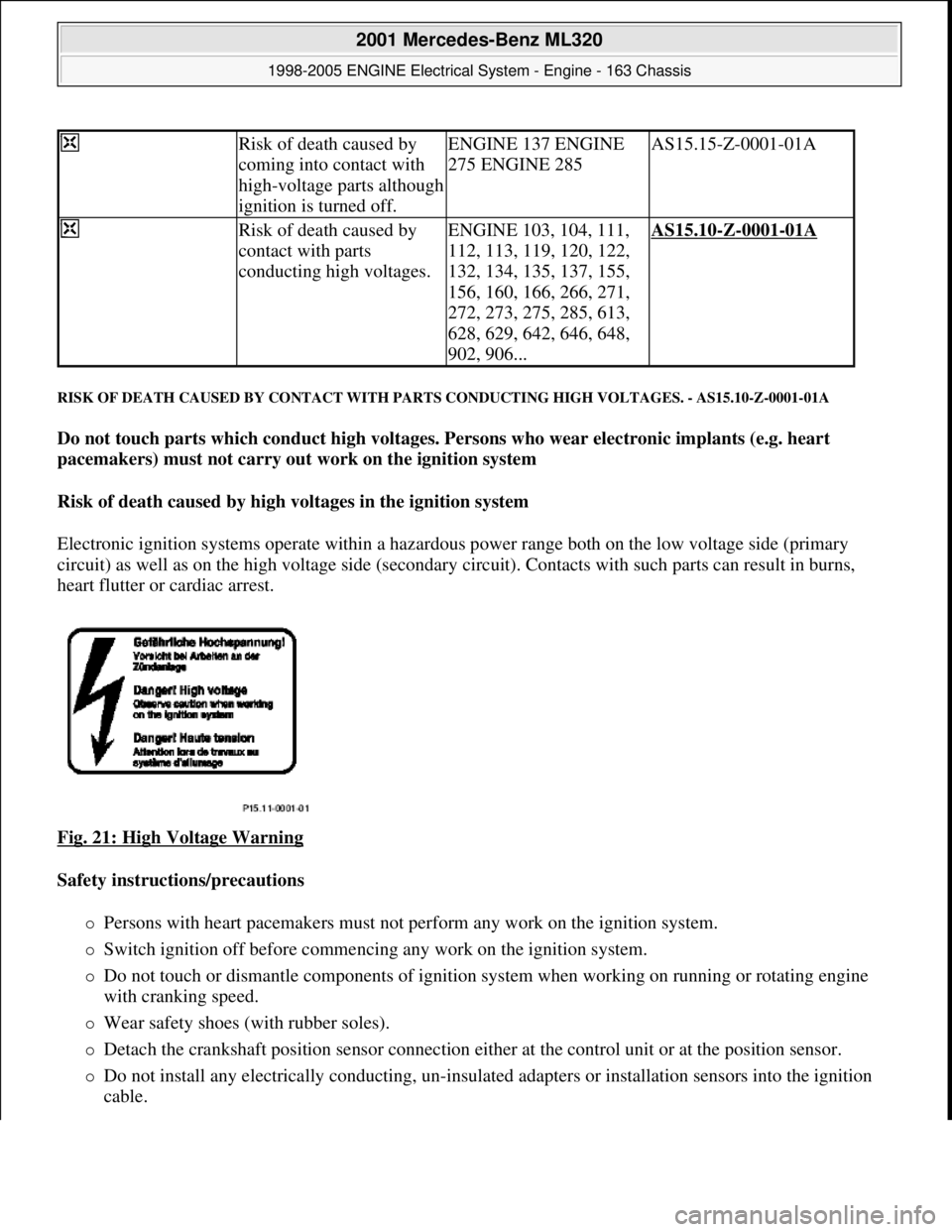
RISK OF DEATH CAUSED BY CONTACT WITH PARTS CONDUCTING HIGH VOLTAGES. - AS15.10-Z-0001-01A
Do not touch parts which conduct high voltages. Persons who wear electronic implants (e.g. heart
pacemakers) must not carry out work on the ignition system
Risk of death caused by high voltages in the ignition system
Electronic ignition systems operate within a hazardous power range both on the low voltage side (primary
circuit) as well as on the high voltage side (secondary circuit). Contacts with such parts can result in burns,
heart flutter or cardiac arrest.
Fig. 21: High Voltage Warning
Safety instructions/precautions
Persons with heart pacemakers must not perform any work on the ignition system.
Switch ignition off before commencing any work on the ignition system.
Do not touch or dismantle components of ignition system when working on running or rotating engine
with cranking speed.
Wear safety shoes (with rubber soles).
Detach the crankshaft position sensor connection either at the control unit or at the position sensor.
Do not install any electrically conducting, un-insulated adapters or installation sensors into the ignition
cable.
Risk of death caused by
coming into contact with
high-voltage parts although
ignition is turned off.ENGINE 137 ENGINE
275 ENGINE 285AS15.15-Z-0001-01A
Risk of death caused by
contact with parts
conducting high voltages.ENGINE 103, 104, 111,
112, 113, 119, 120, 122,
132, 134, 135, 137, 155,
156, 160, 166, 266, 271,
272, 273, 275, 285, 613,
628, 629, 642, 646, 648,
902, 906...AS15.10-Z-0001-01A
2001 Mercedes-Benz ML320
1998-2005 ENGINE Electrical System - Engine - 163 Chassis
me
Saturday, October 02, 2010 3:18:54 PMPage 30 © 2006 Mitchell Repair Information Company, LLC.
Page 2236 of 4133

GF00.20-P-2009A
Engine oil monitor function
24.10.96
MODEL
129 with ENGINE 112, 113
MODEL
163 with ENGINE 112, 113, 612
MODEL
168 with ENGINE 166, 668
MODEL
202 with ENGINE 112, 611
MODEL
208 up to 31.7.99 with ENGINE 112, 113
MODEL
210 up to 30.6.99 with ENGINE 112, 113, 611
General
The oil level is constantly monitored by the oil sensor, and the
appropriate data transmitted to the processor by the ASSYST.
Oil replenishments are detected automatically and result in a bonus,
which extends the service interval accordingly.
An excess oil level or insufficient oil level appears in the display
together with the oil can symbol.
Display of low oil level at maximum:
D
at driver request
Display of warnings: D
automatically, at the earliest 60 s after engine start and oil
temperature greater than 60°C:
D
if oil level too high: the oil can symbol appears together
with the readout "OIL LEVEL ABOVE MAX". In addition, a
brief warning signal sounds. (On models not fitted with
multifunction displaly, "HI" appears flashing.)
D
if oil level too low: the oil can symbol appears together with
the readout "OIL LEVEL BELOW MIN". In addition, a brief
warning signal sounds. (On models not fitted with multifunction
display, the oil level warning lamp (A1e12) comes on and the
readout "-2L" appears flashing.)
-----------------------------------------------------------------------------------------
D
if oil at minimum: the oil can symbol appears together with
the readout "OIL LEVEL MINIMUM". In addition, a brief
warning signal sounds. (On models not fitted with multifunction
display, the oil level warning lamp (A1e12) comes on.)
D
automatically 13 s after ignition ON:
D
if
no oil
is in engine: the oil can symbol appears together
with the readout "OIL LEVEL BELOW MIN". In addition, a
warning signal sounds. (On models not fitted with multifunction
display, the oil level warning lamp (A1e12) comes on and the
readout "-2L"appears flashing. In addition a brief warning
signal sounds.)
The missing oil quantity displayed no longer changes during the
display. In other words, any change in oil level cannot be observed
directly at the display. The new oil level is only displayed once the
conditions described below exist.
Display of oil quantity at driver request
The text "DISPLAY OIL LEVEL?" appears 10 s after the start switch
has been turned into position "2" (on models not fitted with
multifunction display, the oil can and the clock symbol are displayed).
If the reset button of the trip counter is pressed twice within one sec.
during this readout, for example, "add 1.0L oil" (or "-1.0L")
-----------------------------------------------------------------------------------------
appears in the display if oil level too low. The readout appears only
after the elapse of a waiting time after engine OFF. The waiting time
depends on the engine oil temperature.
It is
D
up to 20°C
30 minutes
D
from 60°C
1 minute
D
The waiting time is between these two limits at other engine oil
temperatures.
Possible readouts are (text in parenthesis relates to models not fitted
with multifunction display.):
D
"OIL LEVEL OKAY" ("o.k."),
D
1.0L, 1.5L, 2L,
D
"Overfilling" ("HI"),
D
"OBSERVE WAITING TIME" (clock symbol flashing and oil can
symbol),
D
"DISPLAY OIL LEVEL" (clock and oil can symbols.)
If there is a fault at the oil sensor (oil level/temperature/quality, B40)
the oil can symbol and the text "OIL LEVEL SENSOR FAULTY"
appears only 30 s after the fault has occurred.
(On models not fitted with multifunction display, the oil level warning
lamp (A1e12) comes on accordingly.)
For diagnosis, read also the injection system control module (N3)
with the HHT. (The instrument cluster (A1) receives the sensor data
through the CAN from the injection system control module (N3)).
-----------------------------------------------------------------------------------------
Oil change
The ASSYST has to be reset each time the oil is changed. Resetting
ASSYST also resets the remaining time and the remaining distance.
Resetting can be performed at the instrument cluster or using the
HHT.
The following data are stored when the system is reset:
D
current kilometer reading rounded off to 100,
D
total oil replenishments in the last interval,
D
remaining distance,
D
remaining time,
D
product of the quality factors,
D
the data of the last 5 resettings in 5 data sets
These data can only be read with the HHT!
If the specified quantity of oil is not replenished when the oil is
changed, the (internal) start distance is reduced.
Detecting oil replenishments
D
With the
HHT
it is possible to retrieve the last 10 oil
replenishments and the corresponding kilometer readings of
the current interval.
D
In the normal case, detection of an oil replenishment is
displayed by the remaining distance in the instrument cluster
being extended
-----------------------------------------------------------------------------------------
Copyright DaimlerChrysler AG 05.06.2006 CD-Ausgabe G/10/04 . This WIS print-out will not be recorde
d by Modification services.
Page 1
Page 2845 of 4133
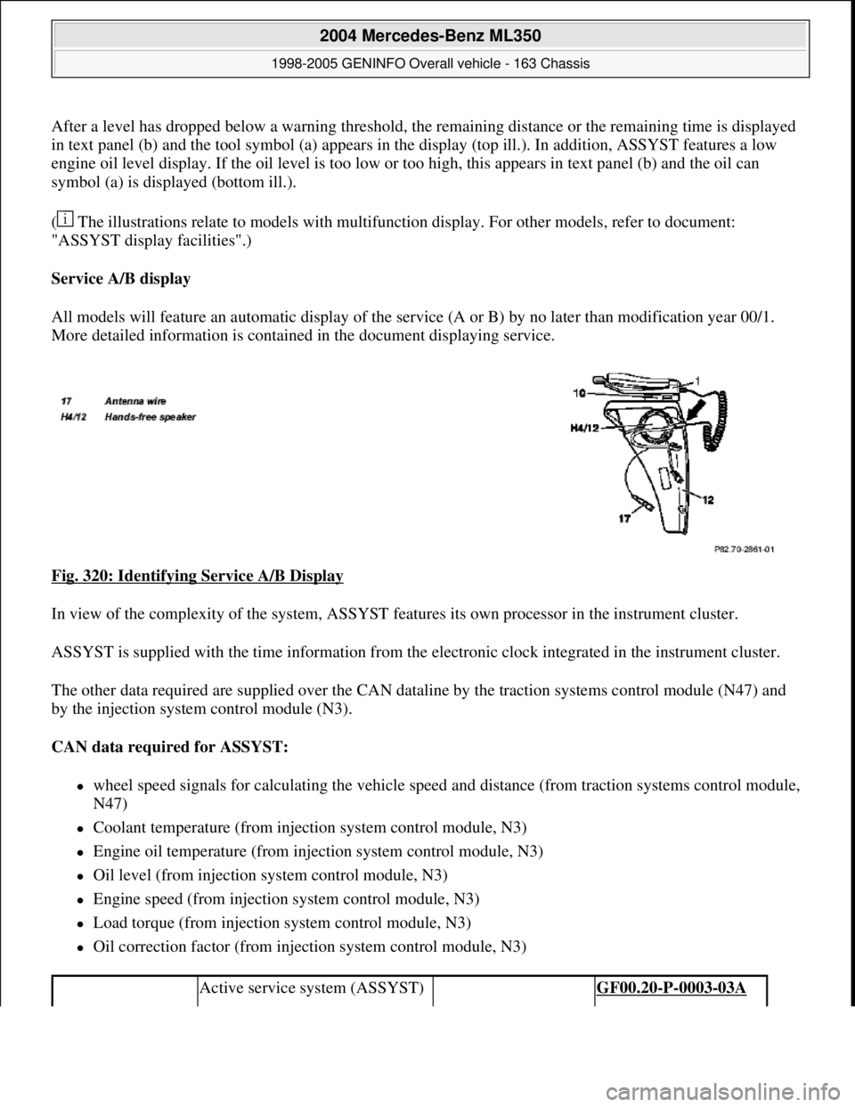
After a level has dropped below a warning threshold, the remaining distance or the remaining time is displayed
in text panel (b) and the tool symbol (a) appears in the display (top ill.). In addition, ASSYST features a low
engine oil level display. If the oil level is too low or too high, this appears in text panel (b) and the oil can
symbol (a) is displayed (bottom ill.).
( The illustrations relate to models with multifunction display. For other models, refer to document:
"ASSYST display facilities".)
Service A/B display
All models will feature an automatic display of the service (A or B) by no later than modification year 00/1.
More detailed information is contained in the document displaying service.
Fig. 320: Identifying Service A/B Display
In view of the complexity of the system, ASSYST features its own processor in the instrument cluster.
ASSYST is supplied with the time information from the electronic clock integrated in the instrument cluster.
The other data required are supplied over the CAN dataline by the traction systems control module (N47) and
by the injection system control module (N3).
CAN data required for ASSYST:
wheel speed signals for calculating the vehicle speed and distance (from traction systems control module,
N47)
Coolant temperature (from injection system control module, N3)
Engine oil temperature (from injection system control module, N3)
Oil level (from injection system control module, N3)
Engine speed (from injection system control module, N3)
Load torque (from injection system control module, N3)
Oil correction factor (from injection system control module, N3)
Active service system (ASSYST) GF00.20-P-0003-03A
2004 Mercedes-Benz ML350
1998-2005 GENINFO Overall vehicle - 163 Chassis
me
Saturday, October 02, 2010 3:47:47 PMPage 200 © 2006 Mitchell Repair Information Company, LLC.
Page 2850 of 4133
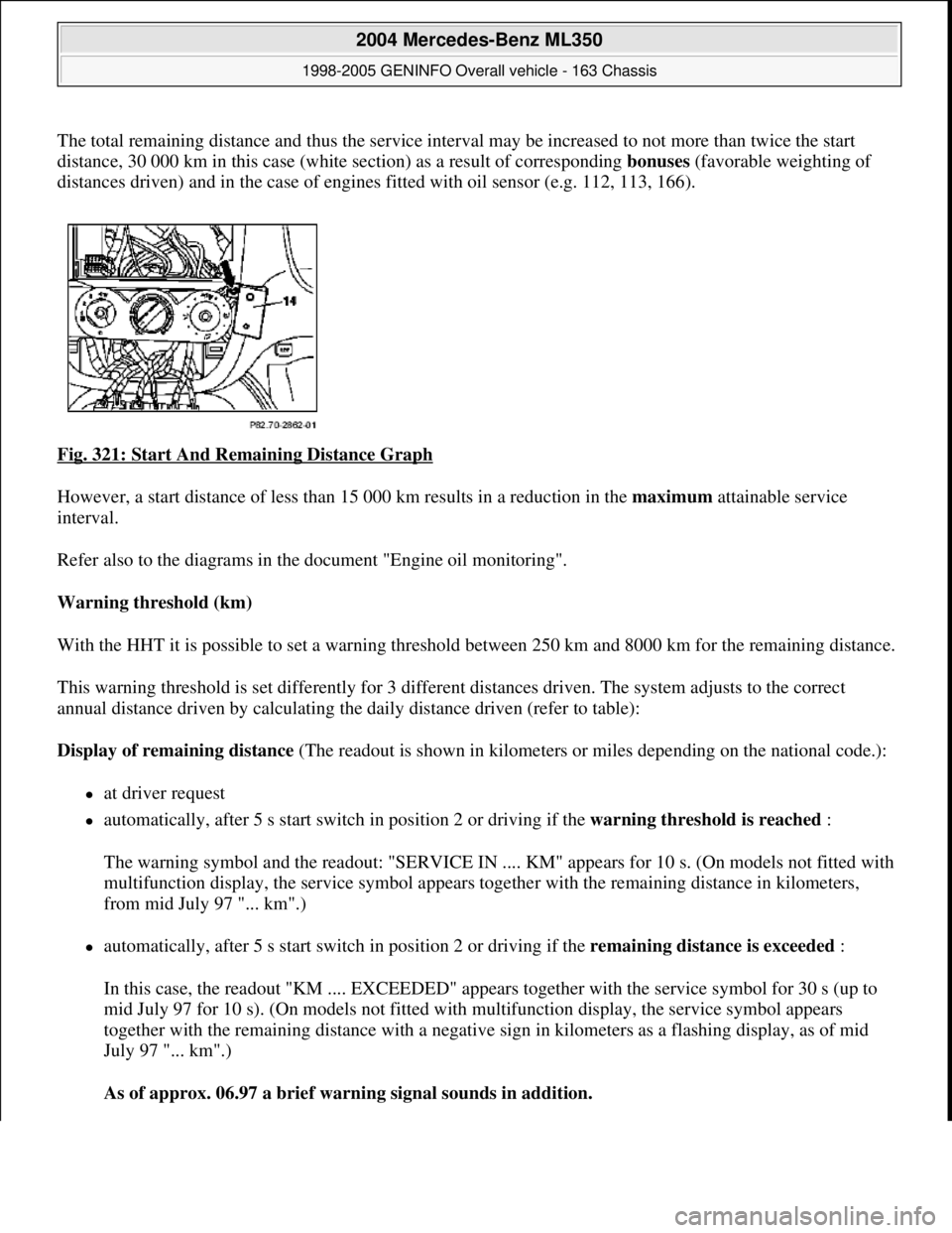
The total remaining distance and thus the service interval may be increased to not more than twice the start
distance, 30 000 km in this case (white section) as a result of corresponding bonuses (favorable weighting of
distances driven) and in the case of engines fitted with oil sensor (e.g. 112, 113, 166).
Fig. 321: Start And Remaining Distance Graph
However, a start distance of less than 15 000 km results in a reduction in the maximum attainable service
interval.
Refer also to the diagrams in the document "Engine oil monitoring".
Warning threshold (km)
With the HHT it is possible to set a warning threshold between 250 km and 8000 km for the remaining distance.
This warning threshold is set differently for 3 different distances driven. The system adjusts to the correct
annual distance driven by calculating the daily distance driven (refer to table):
Display of remaining distance (The readout is shown in kilometers or miles depending on the national code.):
at driver request
automatically, after 5 s start switch in position 2 or driving if the warning threshold is reached :
The warning symbol and the readout: "SERVICE IN .... KM" appears for 10 s. (On models not fitted with
multifunction display, the service symbol appears together with the remaining distance in kilometers,
from mid July 97 "... km".)
automatically, after 5 s start switch in position 2 or driving if the remaining distance is exceeded :
In this case, the readout "KM .... EXCEEDED" appears together with the service symbol for 30 s (up to
mid July 97 for 10 s). (On models not fitted with multifunction display, the service symbol appears
together with the remaining distance with a negative sign in kilometers as a flashing display, as of mid
July 97 "... km".)
As of approx. 06.97 a brief warning signal sounds in addition.
2004 Mercedes-Benz ML350
1998-2005 GENINFO Overall vehicle - 163 Chassis
me
Saturday, October 02, 2010 3:47:47 PMPage 205 © 2006 Mitchell Repair Information Company, LLC.
Page 2853 of 4133
Warning threshold (in days)
With the HHT it is possible to set a warning threshold of between 5 and 30 days for the remaining time, with a
stepwidth of one day. The basic setting is 30 days.
Display of remaining time
The remaining time is always only displayed in those cases where the following condition is met:
Remaining time (in days) x 40 < remaining distance (in km), and the warning threshold is reached.
The remaining time is displayed in the following cases:
automatically, after 5 s start switch in position 2 or driving, if the warning threshold is reached:
The service symbol and the readout "SERVICE IN ... DAYS" appears for 10 seconds. (On vehicles not
fitted with multifunction display, the current remaining time, the service and the clock symbol appear.)
automatically, after 5 s start switch in position 2 or driving, if the remaining time is exceeded:
The service symbol and the readout "DAYS ... EXCEEDED" appears for 30 s (for 10 s up to mid-July
97). (On vehicles not fitted with multifunction display, the service and the clock symbol appear. The
"remaining time" is displayed with a negative sign (minus sign). The readout flashes in this case.)
After the display reaches the maximum readout of -730 days, the readout remains at this figure! The
readout is displayed with a resolution of 1 day.
As of approx. 06.97 a brief warning signal sounds in addition.
at driver request. The readout is then displayed, as above, for 10 s.
If a speed limit is set at the cruise control, this speed limit is displayed for a short moment before the
ASSYST display.
If certain measured values are not supplied to the ASSYST, e.g. because of failure of a sensor, it switches to
stored substitute values. An appropriate entry is then made in the fault memory of the particular control module.
If the power supply fails, the data are retained. The times without operating voltage (battery disconnected) are
not recorded, however! They can be retroactively included, however, with the HHT.
Active service system
(ASSYST) operating
informationEngine with oil sensor
(e.g. 112, 113, 611)GF00.20-P-0003-01A
Model 210 as of 01.03.97
with engines 111, 602,
604, 605, 606
Model 129, 140, 170, 202 GF00.20-P-0003-01B
2004 Mercedes-Benz ML350
1998-2005 GENINFO Overall vehicle - 163 Chassis
me
Saturday, October 02, 2010 3:47:47 PMPage 208 © 2006 Mitchell Repair Information Company, LLC.