1997 MERCEDES-BENZ ML500 warning
[x] Cancel search: warningPage 2855 of 4133
An excess oil level or insufficient oil level appears in the display together with the oil can symbol.
Display of low oil level at maximum:
at driver request
Display of warnings:
automatically, at the earliest 60s after engine start and oil temperature greater than 60°C:
if oil level too high: the oil can symbol appears together with the readout "OIL LEVEL ABOVE
MAX". In addition, a brief warning signal sounds. (On models not fitted with multifunction
display, "HI" appears flashing.)
if oil level too low: the oil can symbol appears together with the readout "OIL LEVEL BELOW
MIN". In addition, a brief warning signal sounds. (On models not fitted with multifunction display,
the oil level warning lamp (A1e12) comes on and the readout "-2L" appears flashing.)
if oil at minimum: the oil can symbol appears together with the readout "OIL LEVEL MINIMUM".
In addition, a brief warning signal sounds. (On models not fitted with multifunction display, the oil
level warning lamp (A1e12) comes on.)
automatically 13 s after ignition ON:
if no oil is in engine: the oil can symbol appears together with the readout "OIL LEVEL BELOW
MIN". In addition, a warning signal sounds. (On models not fitted with multifunction display, the
oil level warning lamp (A1e12) comes on and the readout "-2L" appears flashing. In addition a
brief warning signal sounds.)
The missing oil quantity displayed no longer changes during the display. In other words, any change in oil level
cannot be observed directly at the display. The new oil level is only displayed once the conditions described
below exist.
Display of oil quantity at driver request
The text "DISPLAY OIL LEVEL?" appears 10 s after the start switch has been turned into position "2" (on
models not fitted with multifunction display, the oil can and the clock symbol are displayed).
If the reset button of the trip counter is pressed twice within one sec. during this readout, for example, "add 1.0L
oil" (or "-1.0L")
appears in the display if oil level too low. The readout appears only after the elapse of a waiting time after
engine OFF. The waiting time depends on the engine oil temperature.
It is
up to 20°C 30 minutes
from 60°C 1 minute
The waiting time is between these two limits at other engine oil temperatures.
2004 Mercedes-Benz ML350
1998-2005 GENINFO Overall vehicle - 163 Chassis
me
Saturday, October 02, 2010 3:47:47 PMPage 210 © 2006 Mitchell Repair Information Company, LLC.
Page 2856 of 4133
Possible readouts are (text in parenthesis relates to models not fitted with multifunction display.):
"OIL LEVEL OKAY" ("o.k."),
1.0L, 1.5L, 2L,
"Overfilling" ("HI"),
"OBSERVE WAITING TIME" (clock symbol flashing and oil can symbol),
"DISPLAY OIL LEVEL" (clock and oil can symbols.)
If there is a fault at the oil sensor (oil level/temperature/quality, B40) the oil can symbol and the text "OIL
LEVEL SENSOR FAULTY" appears only 30 s after the fault has occurred.
(On models not fitted with multifunction display, the oil level warning lamp (A1e12) comes on accordingly.)
For diagnosis, read also the injection system control module (N3) with the HHT. (The instrument cluster (A1)
receives the sensor data through the CAN from the injection system control module (N3)).
Oil change
The ASSYST has to be reset each time the oil is changed. Resetting ASSYST also resets the remaining time and
the remaining distance. Resetting can be performed at the instrument cluster or using the HHT. The following
data are stored when the system is reset:
current kilometer reading rounded off to 100,
total oil replenishments in the last interval,
remaining distance,
remaining time,
product of the quality factors,
the data of the last 5 resettings in 5 data sets
These data can only be read with the HHT!
If the specified quantity of oil is not replenished when the oil is changed, the (internal) start distance is
reduced.
Detecting oil replenishments
With the HHT it is possible to retrieve the last 10 oil replenishments and the corresponding kilometer
readings of the current interval.
In the normal case, detection of an oil replenishment is displayed by the remaining distance in the
instrument cluster being extended
Oil replenishments are always only detected once the following conditions are met:
the replenished quantit
y is at least
2004 Mercedes-Benz ML350
1998-2005 GENINFO Overall vehicle - 163 Chassis
me
Saturday, October 02, 2010 3:47:47 PMPage 211 © 2006 Mitchell Repair Information Company, LLC.
Page 3043 of 4133
These maintenance documents contain instructions relating to carrying out maintenance and repair operations
on Mercedes-Benz passenger cars. They are intended for the exclusive use of workshops affiliated to the
Mercedes-Benz Organization.
The instructions form the basis for proper and competent service and maintenance.
The nature in which the operations are described is based on the training standard of a fitter who has completed
vocational training and has good knowledge of our products. This level of knowledge is essential for carrying
out the described work.
The continuous further development and improvement of our vehicles may lead to deviations between the
actual technical status of the vehicles and the operation descriptions.
DaimlerChrysler AG reserves the right to make alterations and modifications at any time and without prior
notice.
If there are any open questions relating to repair procedures, please take up the matter with the competent
contact person in the relevant national organization (for DCVD refer to valid Service Information Group 99).
Additional information about the breakdown and structure of the work descriptions and the meaning of the
symbols (Logos) can be found in the Workshop Information System WIS.
Each described maintenance operation has a number (operation item) which is stated in the head line. The
operation item in the maintenance manual is identical with that on the SERVICE SHEET for the Active Service
System (ASSYST), enabling the appropriate texts and data to be found straight away if required when
performing maintenance jobs.
Maintenance operations which are not described have no number (operation item) on the SERVICE SHEET.
The group numbers familiar from the workshop literature are used for the first two digits of the 4-digit operation
item numbers. This ensures the assignment of each maintenance operation to the group.
DaimlerChrysler AG
Global Service & Parts
July 2004
SAFETY NOTES/WARNING NOTES - AP00.20-P-0000-02A
Safety information (hazardous situations for persons), warnings (quality of work, property damage).
These notes are identified by the following symbols (logos):
The logo " " represents safety information (dangerous situations for persons).
The lo
go " "represents a warning (work quality, property damage).
2004 Mercedes-Benz ML350
1998-2005 GENINFO Overall vehicle - 163 Chassis
me
Saturday, October 02, 2010 3:47:52 PMPage 398 © 2006 Mitchell Repair Information Company, LLC.
Page 3047 of 4133
SPECIAL SERVICE PROCEDURES - AP00.20-P-0000-06B
Have the brake fluid replaced if more than 2 years have elapsed since the last change; this is best done in the
spring.
The coolant should be inspected for correct anticorrosion/ antifreeze concentration before the beginning of, and
during the cold season of the year. Depending on the model series, the coolant has to be replaced every 3 years
or 15 years (or after 250,000 km).
Refer to the particular valid service sheet for further additional operations based on kilometers or years.
SERVICE DATE REMINDER - AP00.20-P-0000-07B
The confirmation in the service booklet must be filled out completely and signed for every service (A or B).
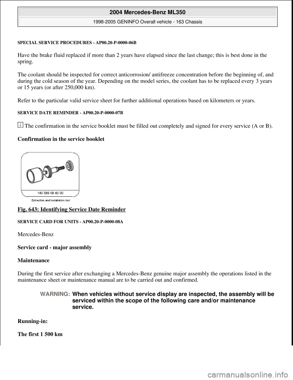
Confirmation in the service booklet
Fig. 643: Identifying Service Date Reminder
SERVICE CARD FOR UNITS - AP00.20-P-0000-08A
Mercedes-Benz
Service card - major assembly
Maintenance
During the first service after exchanging a Mercedes-Benz genuine major assembly the operations listed in the
maintenance sheet or maintenance manual are to be carried out and confirmed.
Running-in:
The first 1 500 km
WARNING:When vehicles without service display are inspected, the assembly will be
serviced within the scope of the following care and/or maintenance
service.
2004 Mercedes-Benz ML350
1998-2005 GENINFO Overall vehicle - 163 Chassis
me
Saturday, October 02, 2010 3:47:52 PMPage 402 © 2006 Mitchell Repair Information Company, LLC.
Page 3048 of 4133
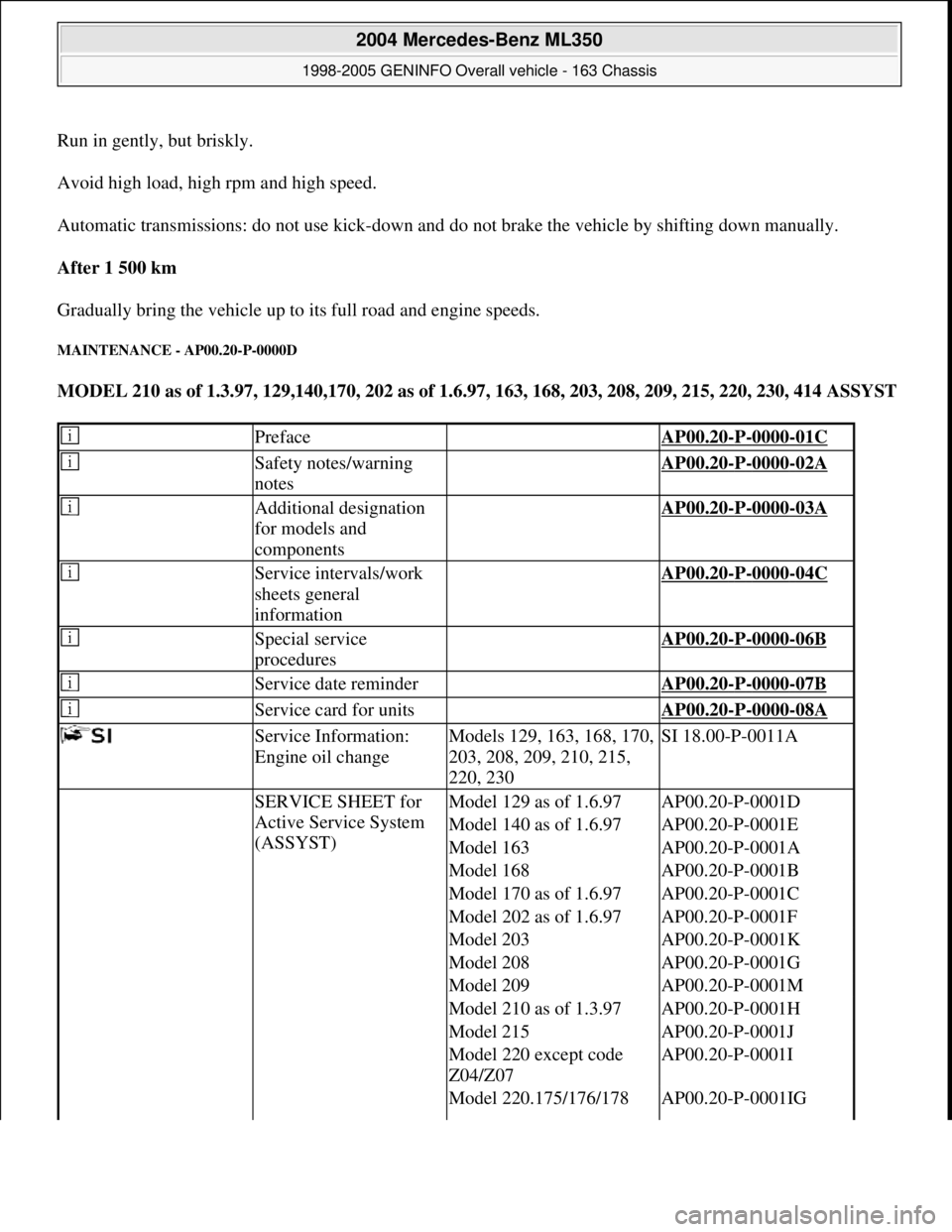
Run in gently, but briskly.
Avoid high load, high rpm and high speed.
Automatic transmissions: do not use kick-down and do not brake the vehicle by shifting down manually.
After 1 500 km
Gradually bring the vehicle up to its full road and engine speeds.
MAINTENANCE - AP00.20-P-0000D
MODEL 210 as of 1.3.97, 129,140,170, 202 as of 1.6.97, 163, 168, 203, 208, 209, 215, 220, 230, 414 ASSYST
Preface AP00.20-P-0000-01C
Safety notes/warning
notes AP00.20-P-0000-02A
Additional designation
for models and
components AP00.20-P-0000-03A
Service intervals/work
sheets general
information AP00.20-P-0000-04C
Special service
procedures AP00.20-P-0000-06B
Service date reminder AP00.20-P-0000-07B
Service card for units AP00.20-P-0000-08A
Service Information:
Engine oil changeModels 129, 163, 168, 170,
203, 208, 209, 210, 215,
220, 230SI 18.00-P-0011A
SERVICE SHEET for
Active Service System
(ASSYST)Model 129 as of 1.6.97AP00.20-P-0001D
Model 140 as of 1.6.97AP00.20-P-0001E
Model 163AP00.20-P-0001A
Model 168AP00.20-P-0001B
Model 170 as of 1.6.97AP00.20-P-0001C
Model 202 as of 1.6.97AP00.20-P-0001F
Model 203AP00.20-P-0001K
Model 208AP00.20-P-0001G
Model 209AP00.20-P-0001M
Model 210 as of 1.3.97AP00.20-P-0001H
Model 215AP00.20-P-0001J
Model 220 except code
Z04/Z07AP00.20-P-0001I
Model 220.175/176/178 AP00.20-P-0001IG
2004 Mercedes-Benz ML350
1998-2005 GENINFO Overall vehicle - 163 Chassis
me
Saturday, October 02, 2010 3:47:52 PMPage 403 © 2006 Mitchell Repair Information Company, LLC.
Page 3185 of 4133

AD54.30-P-2000-02GC
Notes on HHT previous knowledge diagnosis
IC
HHT :
The instrument cluster and active service system (ASSYST) sub-
function are checked with HHT, there being the choice of the
following functions for this:
1. Control module version
2. Fault memory
3. Actual values
4. Actuations
5. Control module adaptation
Additional information on test items 2, 3 and 5 can be called up using
the INPUT key
Control module adaptation
The following alternatives are available in the HHT under control
module adaptation:
1.)
Read out coding and transfer to new instrument cluster. IC and
ASSYST.
2.)
Read out/change codings e.g.:
Engine and national variants,
version of fuel tank,
special equipment etc.
3.)
Settings:
1
Clock
2
Put forward kilometer reading
3
Put back kilometer reading
4
Oil change
5
Reset oil change initiated inadvertently
6
Active Service System
7
Enter times with battery disconnected
8
Set minimum oil warning
Before replacing a defective instrument cluster, readout the existing
variant codings (driving data and instrument cluster data) and store in
the HHT on an interim basis. Read in the values stored on an interim
basis again after installing the new instrument cluster.
If it is not possible to read out the stored variant coding, all variant
codings must be input manually (menu-assistance in HHT).
When installing an instrument cluster on an experimental basis, do
not put forward the kilometer reading as it cannot be put back later.
Copyright DaimlerChrysler AG 05.06.2006 CD-Ausgabe G/10/04 . This WIS print-out will not be recorde
d by Modification services.
Page 1
Page 3212 of 4133
2000-01 MANUAL A/C-HEATER SYSTEMS
ML 320, ML 430 & ML 55
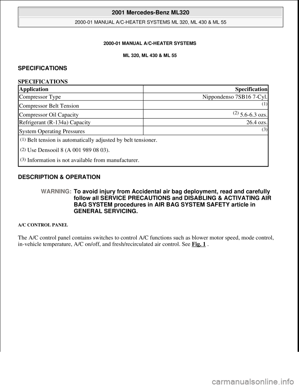
SPECIFICATIONS
SPECIFICATIONS
DESCRIPTION & OPERATION
A/C CONTROL PANEL
The A/C control panel contains switches to control A/C functions such as blower motor speed, mode control,
i
n-vehicle temperature, A/C on/off, and fresh/recirculated air control. See Fig. 1.
ApplicationSpecification
Compressor TypeNippondenso 7SB16 7-Cyl.
Compressor Belt Tension(1)
Compressor Oil Capacity(2) 5.6-6.3 ozs.
Refrigerant (R-134a) Capacity26.4 ozs.
System Operating Pressures(3)
(1)Belt tension is automatically adjusted by belt tensioner.
(2)Use Densooil 8 (A 001 989 08 03).
(3)Information is not available from manufacturer.
WARNING:To avoid injury from Accidental air bag deployment, read and carefully
follow all SERVICE PRECAUTIONS and DISABLING & ACTIVATING AIR
BAG SYSTEM procedures in AIR BAG SYSTEM SAFETY article in
GENERAL SERVICING.
2001 Mercedes-Benz ML320
2000-01 MANUAL A/C-HEATER SYSTEMS ML 320, ML 430 & ML 55
2001 Mercedes-Benz ML320
2000-01 MANUAL A/C-HEATER SYSTEMS ML 320, ML 430 & ML 55
me
Saturday, October 02, 2010 3:25:10 PMPage 1 © 2006 Mitchell Repair Information Company, LLC.
me
Saturday, October 02, 2010 3:25:13 PMPage 1 © 2006 Mitchell Repair Information Company, LLC.
Page 3218 of 4133
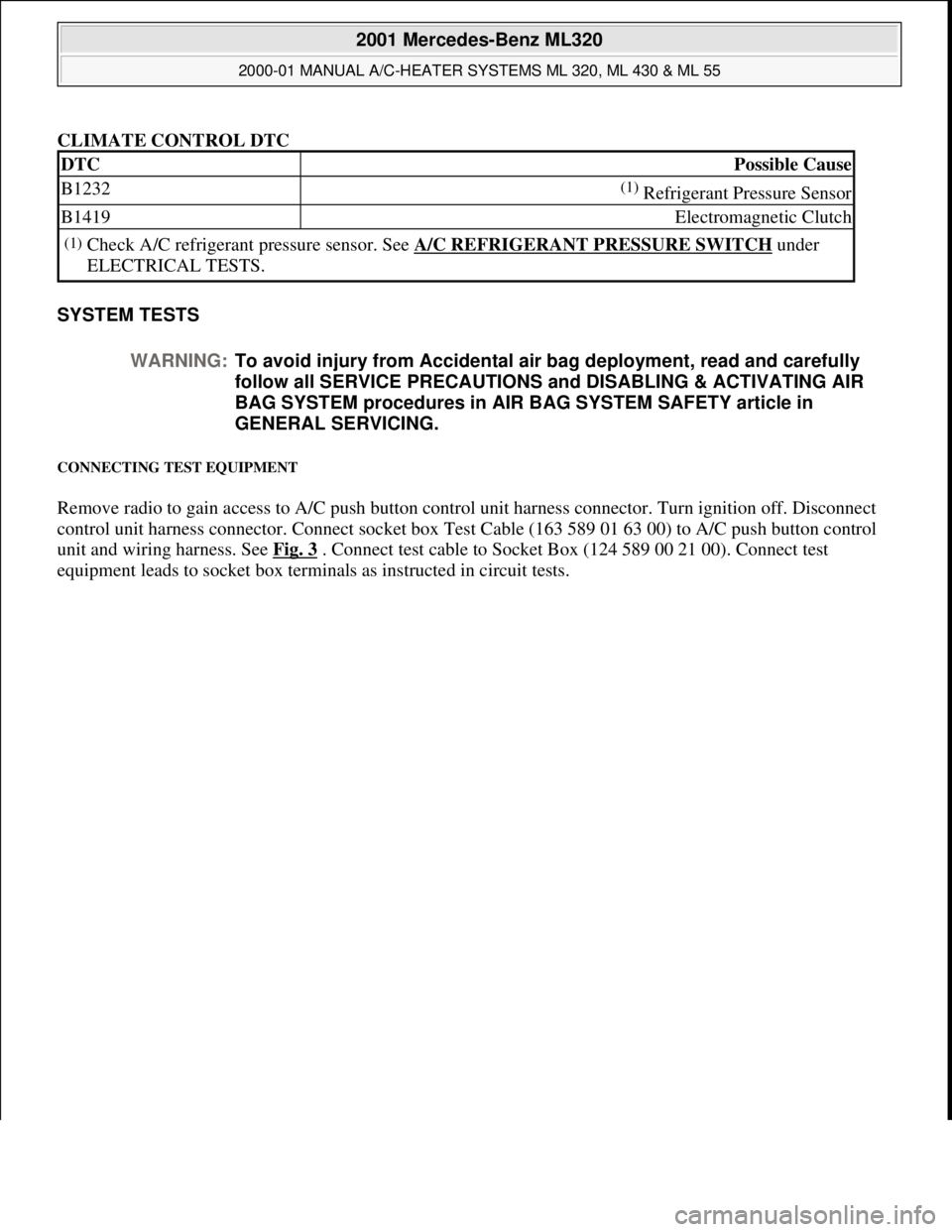
CLIMATE CONTROL DTC
SYSTEM TESTS
CONNECTING TEST EQUIPMENT
Remove radio to gain access to A/C push button control unit harness connector. Turn ignition off. Disconnect
control unit harness connector. Connect socket box Test Cable (163 589 01 63 00) to A/C push button control
unit and wiring harness. See Fig. 3
. Connect test cable to Socket Box (124 589 00 21 00). Connect test
equipment leads to socket box terminals as instructed in circuit tests.
DTCPossible Cause
B1232(1) Refrigerant Pressure Sensor
B1419Electromagnetic Clutch
(1)Check A/C refrigerant pressure sensor. See A/C REFRIGERANT PRESSURE SWITCH under
ELECTRICAL TESTS.
WARNING:To avoid injury from Accidental air bag deployment, read and carefully
follow all SERVICE PRECAUTIONS and DISABLING & ACTIVATING AIR
BAG SYSTEM procedures in AIR BAG SYSTEM SAFETY article in
GENERAL SERVICING.
2001 Mercedes-Benz ML320
2000-01 MANUAL A/C-HEATER SYSTEMS ML 320, ML 430 & ML 55
me
Saturday, October 02, 2010 3:25:10 PMPage 7 © 2006 Mitchell Repair Information Company, LLC.