1997 MERCEDES-BENZ ML500 oil
[x] Cancel search: oilPage 2565 of 4133
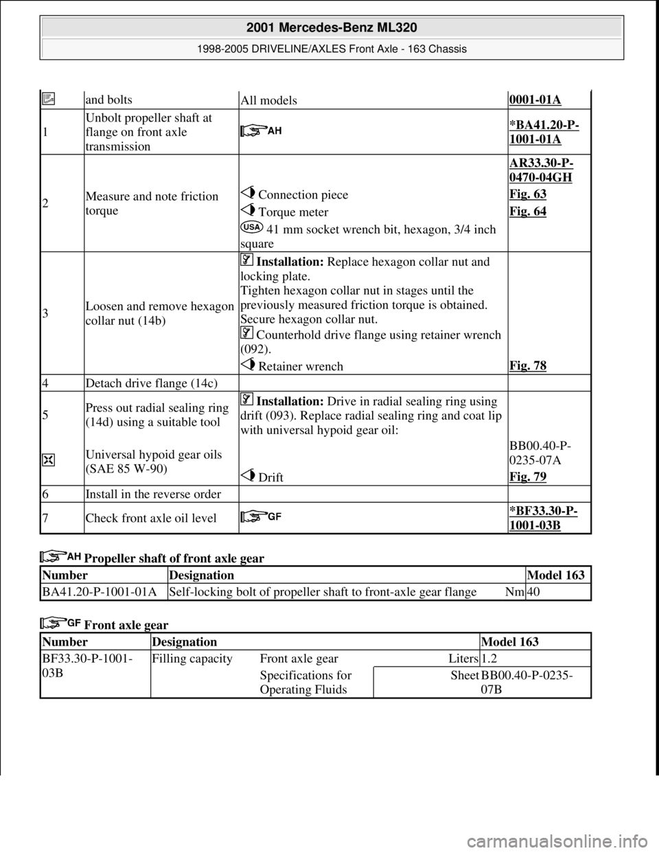
Propeller shaft of front axle gear
Front axle gear
and boltsAll models0001-01A
1
Unbolt propeller shaft at
flange on front axle
transmission
*BA41.20-P-
1001-01A
2Measure and note friction
torque
AR33.30-P-
0470-04GH
Connection pieceFig. 63
Torque meterFig. 64
41 mm socket wrench bit, hexagon, 3/4 inch
square
3Loosen and remove hexagon
collar nut (14b)
Installation: Replace hexagon collar nut and
locking plate.
Tighten hexagon collar nut in stages until the
previously measured friction torque is obtained.
Secure hexagon collar nut.
Counterhold drive flange using retainer wrench
(092).
Retainer wrenchFig. 78
4Detach drive flange (14c)
5Press out radial sealing ring
(14d) using a suitable tool Installation: Drive in radial sealing ring using
drift (093). Replace radial sealing ring and coat lip
with universal hypoid gear oil:
Universal hypoid gear oils
(SAE 85 W-90) BB00.40-P-
0235-07A
DriftFig. 79
6Install in the reverse order
7Check front axle oil level *BF33.30-P-
1001-03B
NumberDesignationModel 163
BA41.20-P-1001-01ASelf-locking bolt of propeller shaft to front-axle gear flangeNm40
NumberDesignationModel 163
BF33.30-P-1001-
03BFilling capacity Front axle gearLiters1.2
Specifications for
Operating FluidsSheetBB00.40-P-0235-
07B
2001 Mercedes-Benz ML320
1998-2005 DRIVELINE/AXLES Front Axle - 163 Chassis
me
Saturday, October 02, 2010 3:38:22 PMPage 46 © 2006 Mitchell Repair Information Company, LLC.
Page 2567 of 4133
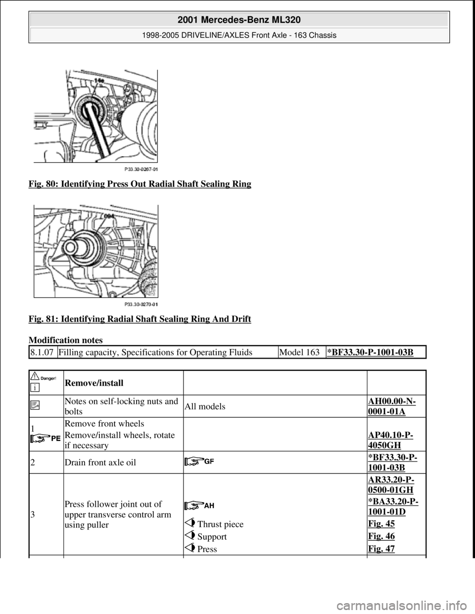
Fig. 80: Identifying Press Ou t Radial Shaft Sealing Ring
Fig. 81: Identifying Radial Sh aft Sealing Ring And Drift
Modification notes
8.1.07Filling capacity, Specificat ions for Operating FluidsModel 163*BF33.30-P-1001-03B
Remove/install
Notes on self-locking nuts and
boltsAll modelsAH00.00-N-
0001-01A
1
Remove front wheels
Remove/install wheels, rotate
if necessaryAP40.10-P-
4050GH
2Drain front axle oil *BF33.30-P-
1001-03B
3
Press follower joint out of
upper transverse control arm
using puller
AR33.20-P-
0500-01GH
*BA33.20-P-
1001-01D
Thrust pieceFig. 45
SupportFig. 46
PressFig. 47
2001 Mercedes-Benz ML320
1998-2005 DRIVELINE/AXLES Front Axle - 163 Chassis
me
Saturday, October 02, 2010 3:38:22 PMPage 48 © 2006 Mitchell Repair Information Company, LLC.
Page 2568 of 4133
Wheel location, hub
Front axle gear
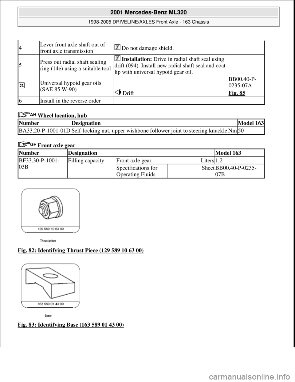
Fig. 82: Identifying Thrust Piece (129 589 10 63 00)
Fig. 83: Identifying Base (163 589 01 43 00)
4Lever front axle shaft out of
front axle transmission Do not damage shield.
5Press out radial shaft sealing
ring (14e) using a suitable tool Installation: Drive in radial shaft seal using
drift (094). Install new radial shaft seal and coat
lip with universal hypoid gear oil.
Universal hypoid gear oils
(SAE 85 W-90) BB00.40-P-
0235-07A
DriftFig. 85
6Install in the reverse order
NumberDesignationModel 163
BA33.20-P-1001-01DSelf-locking nut, upper wishbone foll ower joint to steering knuckleNm50
NumberDesignationModel 163
BF33.30-P-1001-
03BFilling capacityFront axle gearLiters1.2
Specifications for
Operating FluidsSheetBB00.40-P-0235-
07B
2001 Mercedes-Benz ML320
1998-2005 DRIVELINE/AXLES Front Axle - 163 Chassis
me
Saturday, October 02, 2010 3:38:22 PMPage 49 © 2006 Mitchell Repair Information Company, LLC.
Page 2589 of 4133
AP47.20-P-0780BB
Replace fuel filter
2.3.99
ENGINE
611.960 in MODEL 202.133 /134 /193 /194
ENGINE
611.961 in MODEL 210.006 /007 /206 /606
ENGINE
612.961 in MODEL 210.016 /216 /616
ENGINE
612.963 in MODEL 163.113
ENGINE
613.961 in MODEL 210.026 /226
ENGINE
613.960 in MODEL 220.026 /126
P47.20-0289-01
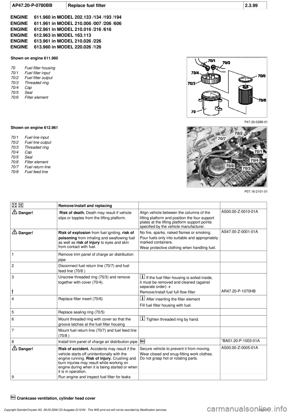
Shown on engine 611.960
70
Fuel filter housing
70/1
Fuel filter input
70/2
Fuel filter output
70/3
Threaded ring
70/4
Cap
70/5
Seal
70/6
Filter element
P07.16-2101-01
Shown on engine 612.961
70/1
Fuel line input
70/2
Fuel line output
70/3
Threaded ring
70/4
Cap
70/5
Seal
70/6
Filter element
70/7
Fuel return line
70/8
Fuel feed line
Remove/install and replacing
Danger!
Risk of death.
Death may result if vehicle
slips or topples from the lifting platform.
Align vehicle between the columns of the
lifting platform and position the four support
plates
at the lifting platform support points
specified by the vehicle manufacturer.
AS00.00-Z-0010-01A
Danger!
Risk of explosion
from fuel igniting,
risk of
poisoning
from inhaling and swallowing fuel
as well as
risk of injury
to eyes and skin
from contact with fuel.
No fire, sparks, naked flames or smoking.
Pour fuels only into suitable and appropriately
marked containers.
Wear protective clothing when handling fuel.
AS47.00-Z-0001-01A
1
Remove trim panel of charge air distribution
pipe
2
Disconnect fuel return line (70/7) and fuel
feed line (70/8 )
3
Unscrew threaded ring (70/3) and remove
together with cover (70/4).
If the fuel filter housing is soiled inside,
it must be removed and cleaned (against
separate order):
#
f
Remove/install fuel full-flow filter
AR47.20-P-1070HB
4
Replace filter insert (70/6)
After inserting the filter element
Fill fuel filter housing with fuel.
5
Replace sealing ring (70/5)
6
Mount threaded ring with cover so that the
groove latches at the fuel filter housing
Tighten threaded ring by hand.
7
Mount fuel return line (70/7) and fuel feed line
(70/8 )
8
Install trim panel of charge air distribution pipe
*BA01.20-P-1003-01A
Danger!
Risk of accident.
Accidents may result if the
vehicle starts off unintentionally with the
engine running.
Risk of injury.
Crushing and
burn injuries may result while working on
engine during when it is being started or when
it is in operation.
Secure vehicle to prevent it from moving.
Wear closed and snug-fitting work clothes.
Do not grasp hot or rotating parts.
AS00.00-Z-0005-01A
9
Run engine and inspect fuel filter for leaks
Crankcase ventilation, cylinder head cover
Copyright DaimlerChrysler AG 28.05.2006 CD-Ausgabe G/10/04 . This WIS print-out will not be recorde
d by Modification services.
Page 1
Page 2597 of 4133

2
Remove covers at seat frame of 60% bench
seat
As of VIN A145273, X708319.
AR91.12-P-1100GH
Only remove the covers which are
identified in the document with A, D and E.
3
Fold 60% bench seat forward into footwell
As of VIN A145273, X708319. See
operator's manual.
4
Pull floor covering below rear seat mounting
bracket (1) of 60% seat forward
Ensure that the floor covering is not torn
when pulled forward.
As of VIN A145273, X708319.
5
Pull floor covering below front corner of trim
panel of C-pillar (2) forward
Ensure that the floor covering is not torn
when pulled forward.
As of VIN A145273, X708319.
6
Cut into floor covering directly behind seat
retaining cable (5)
Ensure that the wiring harness (4) is not
damaged when cutting into floor covering.
As of VIN A145273, X708319. broken line
marks cut-in.
7
Turn back floor covering to gain access to
cap (84)
Do not kink floor covering.
8
Remove cap (84)
Cap (84) is sealed in with body sealer.
Heat with hot air blower to make it easier to
remove.
Installation:
Replace cap and install with
new sealing compound.
9
Detach fuel feed line (90/12) and fuel return
line (90/11) and, if fitted, the fuel line at
connection (90/13)
Do not kink the fuel lines.
If no stationary heater is fitted to vehicle,
do not remove connection (90/13) otherwise
housing will be damaged.
*163589003700
10
Remove nut (89)
*163589010700
*BA47.20-P-1006-01B
11
Remove housing (3)
Fuel lever sensor and housing are a
single part and cannot be removed separately.
Installation:
Re-install nut (89) together
with seal (89/2).
Apply a thin film of oil to seal.
12
Install in the reverse order
Fuel pump
Number
Designation
Engine 612Engine 628
BA47.20-P-1006-01B
Union nut for fuel tank sensor on fuel
tank
Nm
6565
Fuel tank
Number
Designation
Models
163.113/
136/154/
172 up to
31.08.01
Model
163.113/
136/154/
172 as of
01.09.01
Model
163.157/
175
Model
163.128
BF47.10-P-1001-01A
Fuel tank capacity
Total capacity
Liter
728383
Reserve capacity
Liter
101212
Copyright DaimlerChrysler AG 28.05.2006 CD-Ausgabe G/10/04 . This WIS print-out will not be recorde
d by Modification services.
Page 2
Page 2646 of 4133
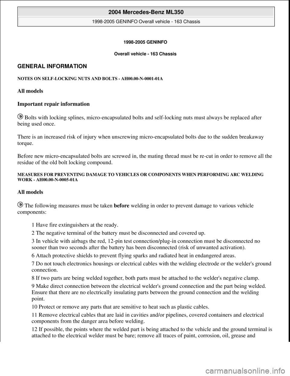
1998-2005 GENINFO
Overall vehicle - 163 Chassis
GENERAL INFORMATION
NOTES ON SELF-LOCKING NUTS AND BOLTS - AH00.00-N-0001-01A
All models
Important repair information
Bolts with locking splines, micro-encapsulated bolts and self-locking nuts must always be replaced after
being used once.
There is an increased risk of injury when unscrewing micro-encapsulated bolts due to the sudden breakaway
torque.
Before new micro-encapsulated bolts are screwed in, the mating thread must be re-cut in order to remove all the
residue of the old bolt locking compound.
MEASURES FOR PREVENTING DAMAGE TO VEHICLES OR COMPONENTS WHEN PERFORMING ARC WELDING
WORK - AH00.00-N-0005-01A
All models
The following measures must be taken before welding in order to prevent damage to various vehicle
components:
1 Have fire extinguishers at the ready.
2 The negative terminal of the battery must be disconnected and covered up.
3 In vehicle with airbags the red, 12-pin test connection/plug-in connection must be disconnected no
sooner than two seconds after the battery has been disconnected (risk of unwanted activation).
6 Attach protective shields to prevent flying sparks and radiated heat in endangered areas.
7 Do not touch electronics housings or electrical cables with the welding electrode or the welder's ground
connection.
8 If two parts are being welded together, both parts must be attached to the welder's negative clamp.
9 Make direct connection between the electrical welder's ground connection and the part being welded.
Ensure that there are no electrically insulating parts between the ground connection and the welding
point.
10 Protect or remove any parts that are sensitive to heat such as plastic cables.
11 Remove electrical cables that are laid in cavities and/or pipelines, covered containers and electrical
components from the danger area before welding.
12 If possible, the points where the welded part is being attached to the vehicle and the ground terminal is
attached to the electrical welder must be bare; remove all traces of paint, corrosion, oil, grease and
2004 Mercedes-Benz ML350
1998-2005 GENINFO Overall vehicle - 163 Chassis
2004 Mercedes-Benz ML350
1998-2005 GENINFO Overall vehicle - 163 Chassis
me
Saturday, October 02, 2010 3:47:43 PMPage 1 © 2006 Mitchell Repair Information Company, LLC.
me
Saturday, October 02, 2010 3:48:01 PMPage 1 © 2006 Mitchell Repair Information Company, LLC.
Page 2647 of 4133
soiling.
13 The ground terminal of the welder must not be attached to the transmission. The welding current can
cause arcing at the bearing points inside the transmission. The structural changes that this causes lead to
premature failure of the equipment.
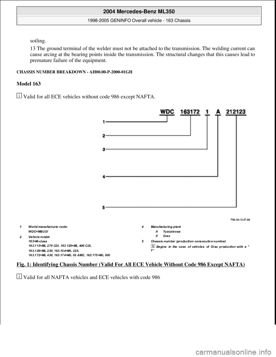
CHASSIS NUMBER BREAKDOWN - AH00.00-P-2000-01GH
Model 163
Valid for all ECE vehicles without code 986 except NAFTA.
Fig. 1: Identifying Chassis Number (Valid For All ECE Vehicle Without Code 986 Except NAFTA)
Valid for all NAFTA vehicles and ECE vehicles with code 986
2004 Mercedes-Benz ML350
1998-2005 GENINFO Overall vehicle - 163 Chassis
me
Saturday, October 02, 2010 3:47:44 PMPage 2 © 2006 Mitchell Repair Information Company, LLC.
Page 2654 of 4133
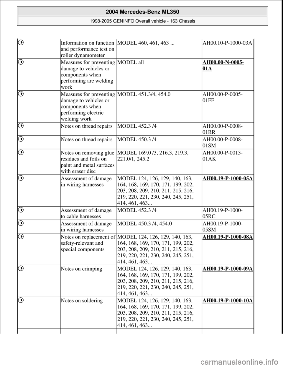
Information on function
and performance test on
roller dynamometerMODEL 460, 461, 463 ...AH00.10-P-1000-03A
Measures for preventing
damage to vehicles or
components when
performing arc welding
workMODEL allAH00.00-N-0005-
01A
Measures for preventing
damage to vehicles or
components when
performing electric
welding workMODEL 451.3/4, 454.0AH00.00-P-0005-
01FF
Notes on thread repairsMODEL 452.3 /4AH00.00-P-0008-
01RR
Notes on thread repairsMODEL 450.3 /4AH00.00-P-0008-
01SM
Notes on removing glue
residues and foils on
paint and metal surfaces
with eraser discMODEL 169.0 /3, 216.3, 219.3,
221.0/1, 245.2AH00.00-P-0013-
01AK
Assessment of damage
in wiring harnessesMODEL 124, 126, 129, 140, 163,
164, 168, 169, 170, 171, 199, 202,
203, 208, 209, 210, 211, 215, 216,
219, 220, 221, 230, 240, 245, 251,
414, 461, 463...AH00.19-P-1000-05A
Assessment of damage
to cable harnessesMODEL 452.3 /4AH00.19-P-1000-
05RC
Assessment of damage
in wiring harnessesMODEL 450.3 /4, 454.0AH00.19-P-1000-
05SM
Notes on replacement of
safety-relevant and
special componentsMODEL 124, 126, 129, 140, 163,
164, 168, 169, 170, 171, 199, 202,
203, 208, 209, 210, 211, 215, 216,
219, 220, 221, 230, 240, 245, 251,
414, 461, 463...AH00.19-P-1000-08A
Notes on crimpingMODEL 124, 126, 129, 140, 163,
164, 168, 169, 170, 171, 199, 202,
203, 208, 209, 210, 211, 215, 216,
219, 220, 221, 230, 240, 245, 251,
414, 461, 463...AH00.19-P-1000-09A
Notes on solderingMODEL 124, 126, 129, 140, 163,
164, 168, 169, 170, 171, 199, 202,
203, 208, 209, 210, 211, 215, 216,
219, 220, 221, 230, 240, 245, 251,
414, 461, 463...AH00.19-P-1000-10A
2004 Mercedes-Benz ML350
1998-2005 GENINFO Overall vehicle - 163 Chassis
me
Saturday, October 02, 2010 3:47:44 PMPage 9 © 2006 Mitchell Repair Information Company, LLC.