Page 2509 of 4133

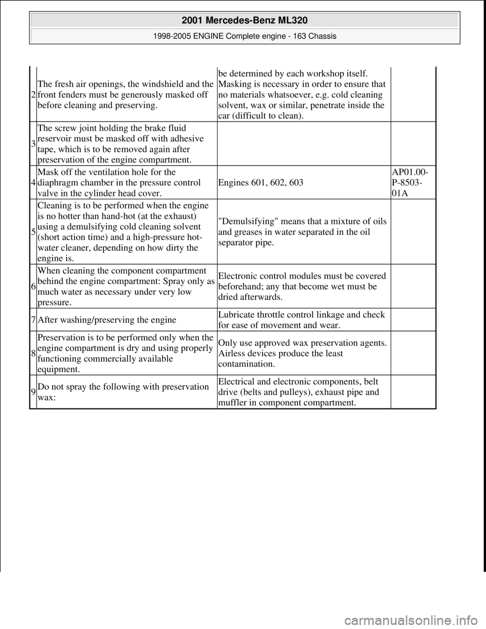
2
The fresh air openings, the windshield and the
front fenders must be generously masked off
before cleaning and preserving.
be determined by each workshop itself.
Masking is necessary in order to ensure that
no materials whatsoever, e.g. cold cleaning
solvent, wax or similar, penetrate inside the
car (difficult to clean).
3
The screw joint holding the brake fluid
reservoir must be masked off with adhesive
tape, which is to be removed again after
preservation of the engine compartment.
4
Mask off the ventilation hole for the
diaphragm chamber in the pressure control
valve in the cylinder head cover.
Engines 601, 602, 603
AP01.00-
P-8503-
01A
5
Cleaning is to be performed when the engine
is no hotter than hand-hot (at the exhaust)
using a demulsifying cold cleaning solvent
(short action time) and a high-pressure hot-
water cleaner, depending on how dirty the
engine is.
"Demulsifying" means that a mixture of oils
and greases in water separated in the oil
separator pipe.
6
When cleaning the component compartment
behind the engine compartment: Spray only as
much water as necessary under very low
pressure.Electronic control modul es must be covered
beforehand; any that become wet must be
dried afterwards.
7After washing/preserving the engineLubricate throttle cont rol linkage and check
for ease of movement and wear.
8
Preservation is to be performed only when the
engine compartment is dry and using properly
functioning commercially available
equipment.Only use approved wax preservation agents.
Airless devices produce the least
contamination.
9Do not spray the follow ing with preservation
wax:Electrical and electroni c components, belt
drive (belts and pulleys), exhaust pipe and
muffler in component compartment.
2001 Mercedes-Benz ML320
1998-2005 ENGINE Complete engine - 163 Chassis
me
Saturday, October 02, 2010 3:17:58 PMPage 153 © 2006 Mitchell Repair Information Company, LLC.
Page 2512 of 4133
AP18.00-P-0101-02Z
Extract engine oil
Commercially available tools
(see Workshop Equipment Manual)
Number
Designation
Make (e. g.)
Order number
WH58.30-Z-1007-16A
Engine oil extractor
Deutsche Tecalemit
Am Metallwerk 11
33659 Bielefeld
1.386950.2
P18.00-0019-01
Shown on Engine 104
1
Extract engine oil through the dipstick guide tube.
Perform only when engine is at normal operating temperature.
Copyright DaimlerChrysler AG 20.05.2006 CD-Ausgabe G/10/04 . This WIS print-out will not be recorde
d by Modification services.
Page 1
Page 2524 of 4133

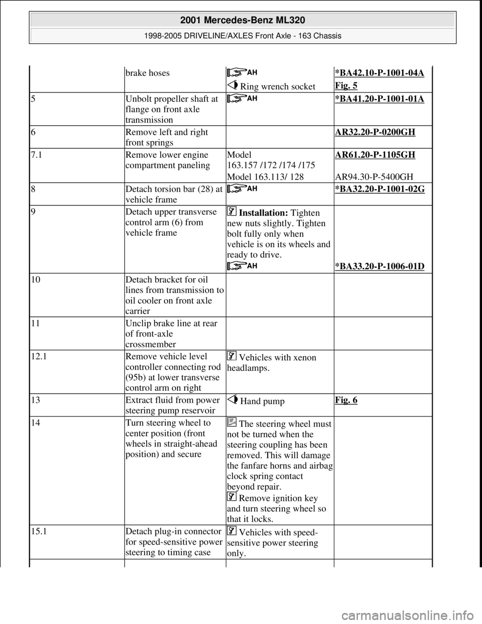
brake hoses *BA42.10-P-1001-04A
Ring wrench socketFig. 5
5Unbolt propeller shaft at
flange on front axle
transmission *BA41.20-P-1001-01A
6Remove left and right
front springs AR32.20-P-0200GH
7.1Remove lower engine
compartment panelingModel
163.157 /172 /174 /175AR61.20-P-1105GH
Model 163.113/ 128AR94.30-P-5400GH
8Detach torsion bar (28) at
vehicle frame *BA32.20-P-1001-02G
9Detach upper transverse
control arm (6) from
vehicle frame Installation: Tighten
new nuts slightly. Tighten
bolt fully only when
vehicle is on its wheels and
ready to drive.
*BA33.20-P-1006-01D
10Detach bracket for oil
lines from transmission to
oil cooler on front axle
carrier
11Unclip brake line at rear
of front-axle
crossmember
12.1Remove vehicle level
controller connecting rod
(95b) at lower transverse
control arm on right Vehicles with xenon
headlamps.
13Extract fluid from power
steering pump reservoir Hand pumpFig. 6
14Turn steering wheel to
center position (front
wheels in straight-ahead
position) and secureThe steering wheel must
not be turned when the
steering coupling has been
removed. This will damage
the fanfare horns and airbag
clock spring contact
beyond repair.
Remove ignition key
and turn steering wheel so
that it locks.
15.1Detach plug-in connector
for speed-sensitive power
steering to timing case Vehicles with speed-
sensitive power steering
only.
2001 Mercedes-Benz ML320
1998-2005 DRIVELINE/AXLES Front Axle - 163 Chassis
me
Saturday, October 02, 2010 3:38:21 PMPage 5 © 2006 Mitchell Repair Information Company, LLC.
Page 2531 of 4133
Fig. 12: Identifying Extraction A nd Installation Tool (163 589 02 43 00)
REMOVE/INSTALL FRONT AXLE HALF - AR33.10-P-0200GH
MODEL 163.113 /128 /136 /154 /157 /172 /174 /175
Fig. 13: Identifying Front Axle Half Components
Location in major assembly compartment on left or right
2axle gear mountingtransmission oil pipes.01GH
Extraction and insertion toolFig. 7
3Install in the reverse order
2001 Mercedes-Benz ML320
1998-2005 DRIVELINE/AXLES Front Axle - 163 Chassis
me
Saturday, October 02, 2010 3:38:22 PMPage 12 © 2006 Mitchell Repair Information Company, LLC.
Page 2559 of 4133
Fig. 64: Identifying Torque Meter (001 589 49 21 00)
Commercially available tools
1. Measure and note friction torque using torque meter (040b) and connecting piece on the hexagon collared
nut.
Fig. 65: Identifying Torque Meter
CHECK FRONT AXLE GEAR OIL LEVEL AND TOP UP IF NECESSARY - AR33.30-P-0525-02GH
Modification notes
Front final-drive unit
Front axle gear
NumberDesignation
WH58.30-Z-1013-06AWrench bit 41 mm hexagon 3/4 inch four-point
8.1.07Filling capacity, Specifications for Operating FluidsModel 163*BF33.30-P-1001-03B
NumberDesignationModel 163
BA33.30-P-1002-03BOil filler screw, front axle gearNm50
BA33.30-P-1003-03BOil drain screw, front axle gearNm50
NumberDesignationModel 163
BF33.30-P-1001-
03BFilling capacityFront axle gearLiters1.2
Specifications for SheetBB00.40-P-0235-
2001 Mercedes-Benz ML320
1998-2005 DRIVELINE/AXLES Front Axle - 163 Chassis
me
Saturday, October 02, 2010 3:38:22 PMPage 40 © 2006 Mitchell Repair Information Company, LLC.
Page 2560 of 4133
1. Clean area around oil fi ller screw (14f).
2. Remove oil filler screw (14f).
The front axle gear is correctly filled when the oil reaches the lower edge of the filler opening. Top up
if necessary. If the oil level check is car ried out when the front axle gear is warm , do not drain off oil
discharged as a result of thermal expansion.
Fig. 66: Identifying Oil Filler Screw
3. Replace seal ring for oil filler screw.
4. Screw in oil filler screw and tighten.
Fig. 67: Identifying Oil Drain Screw
REMOVE/INSTALL FRONT AX LE GEAR - AR33.30-P-0525GH
MODEL 163.113 /128 /136 /154 /157 /172 /174 /175
Operating Fluids07B
2001 Mercedes-Benz ML320
1998-2005 DRIVELINE/AXLES Front Axle - 163 Chassis
me
Saturday, October 02, 2010 3:38:22 PMPage 41 © 2006 Mitchell Repair Information Company, LLC.
Page 2561 of 4133
Fig. 68: Identifying Front Axle Gear Components
Modification notes
8.1.07Filling capacity, Specifications for Operating FluidsModel 163*BF33.30-P-1001-03B
Remove/install
1
Remove front wheels
Remove/install wheels, rotate if
necessaryAP40.10-P-
4050GH
2Drain front axle gear oil
Installation: ?
Check front axle gear oil level and
top up if necessary
Oil drain screw: ?AR33.30-P-
0525-02GH
Oil filler plug: ?*BA33.30-P-
1003-03B
*BA33.30-P-
1002-03B
*BF33.30-P-
1001-03B
3Unbolt propeller shaft at flange on front
axle transmission *BA41.20-P-
1001-01A
4Press both follower joints out of upper
transverse control arms using puller
Check rubber boot and ball joint for
wear and damage.AR33.20-P-
0500-01GH
*BA33.20-P-
1001-01D
2001 Mercedes-Benz ML320
1998-2005 DRIVELINE/AXLES Front Axle - 163 Chassis
me
Saturday, October 02, 2010 3:38:22 PMPage 42 © 2006 Mitchell Repair Information Company, LLC.
Page 2562 of 4133

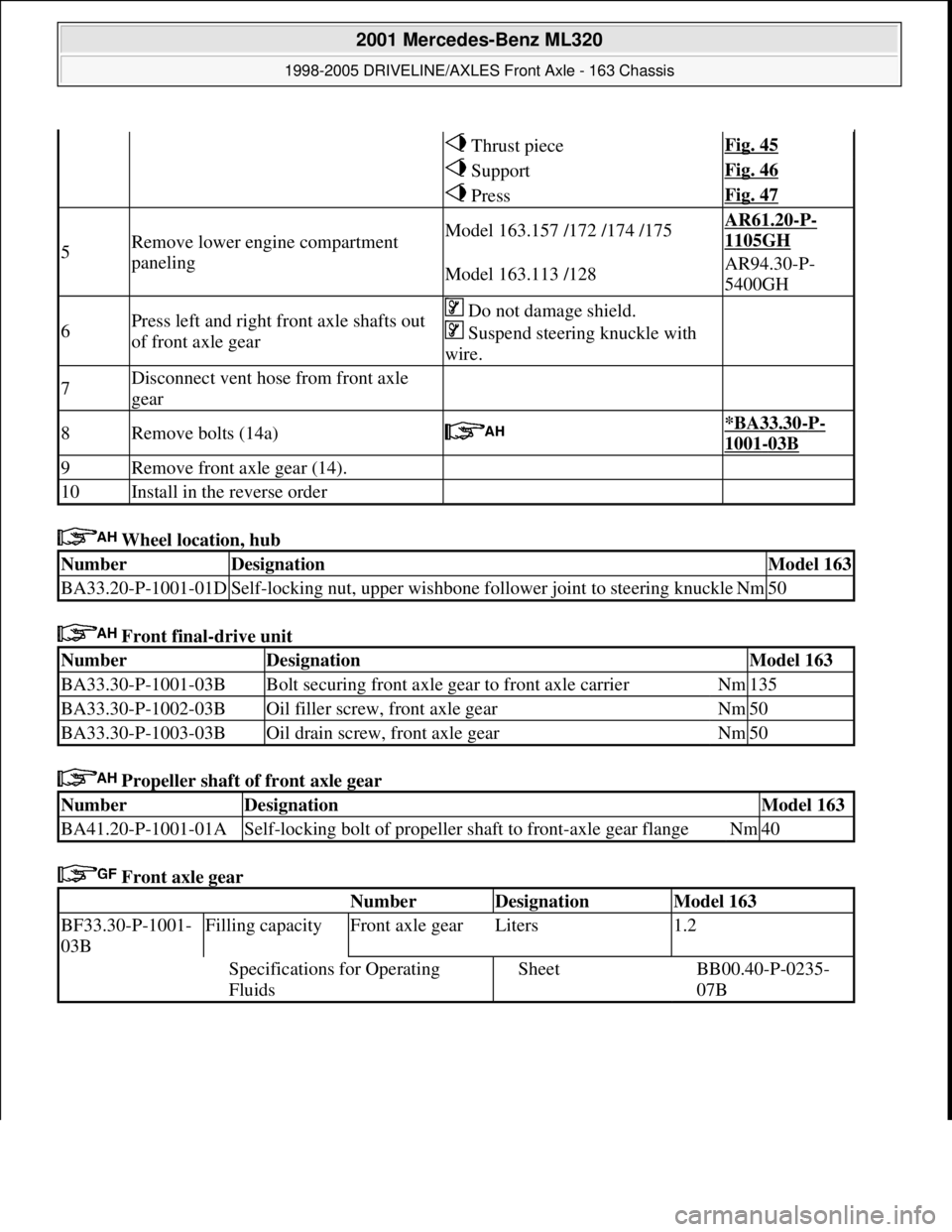
Wheel location, hub
Front final-drive unit
Propeller shaft of front axle gear
Front axle gear
Thrust pieceFig. 45
SupportFig. 46
PressFig. 47
5Remove lower engine compartment
panelingModel 163.157 /172 /174 /175AR61.20-P-
1105GH
Model 163.113 /128AR94.30-P-
5400GH
6Press left and right front axle shafts out
of front axle gear Do not damage shield.
Suspend steering knuckle with
wire.
7Disconnect vent hose from front axle
gear
8Remove bolts (14a) *BA33.30-P-
1001-03B
9Remove front axle gear (14).
10Install in the reverse order
NumberDesignationModel 163
BA33.20-P-1001-01DSelf-locking nut, upper wishbone follower joint to steering knuckleNm50
NumberDesignationModel 163
BA33.30-P-1001-03BBolt securing front axle gear to front axle carrierNm135
BA33.30-P-1002-03BOil filler screw, front axle gearNm50
BA33.30-P-1003-03BOil drain screw, front axle gearNm50
NumberDesignationModel 163
BA41.20-P-1001-01ASelf-locking bolt of propeller shaft to front-axle gear flangeNm40
Number Designation Model 163
BF33.30-P-1001-
03BFilling capacityFront axle gearLiters1.2
Specifications for Operating
FluidsSheetBB00.40-P-0235-
07B
2001 Mercedes-Benz ML320
1998-2005 DRIVELINE/AXLES Front Axle - 163 Chassis
me
Saturday, October 02, 2010 3:38:22 PMPage 43 © 2006 Mitchell Repair Information Company, LLC.