Page 2423 of 4133

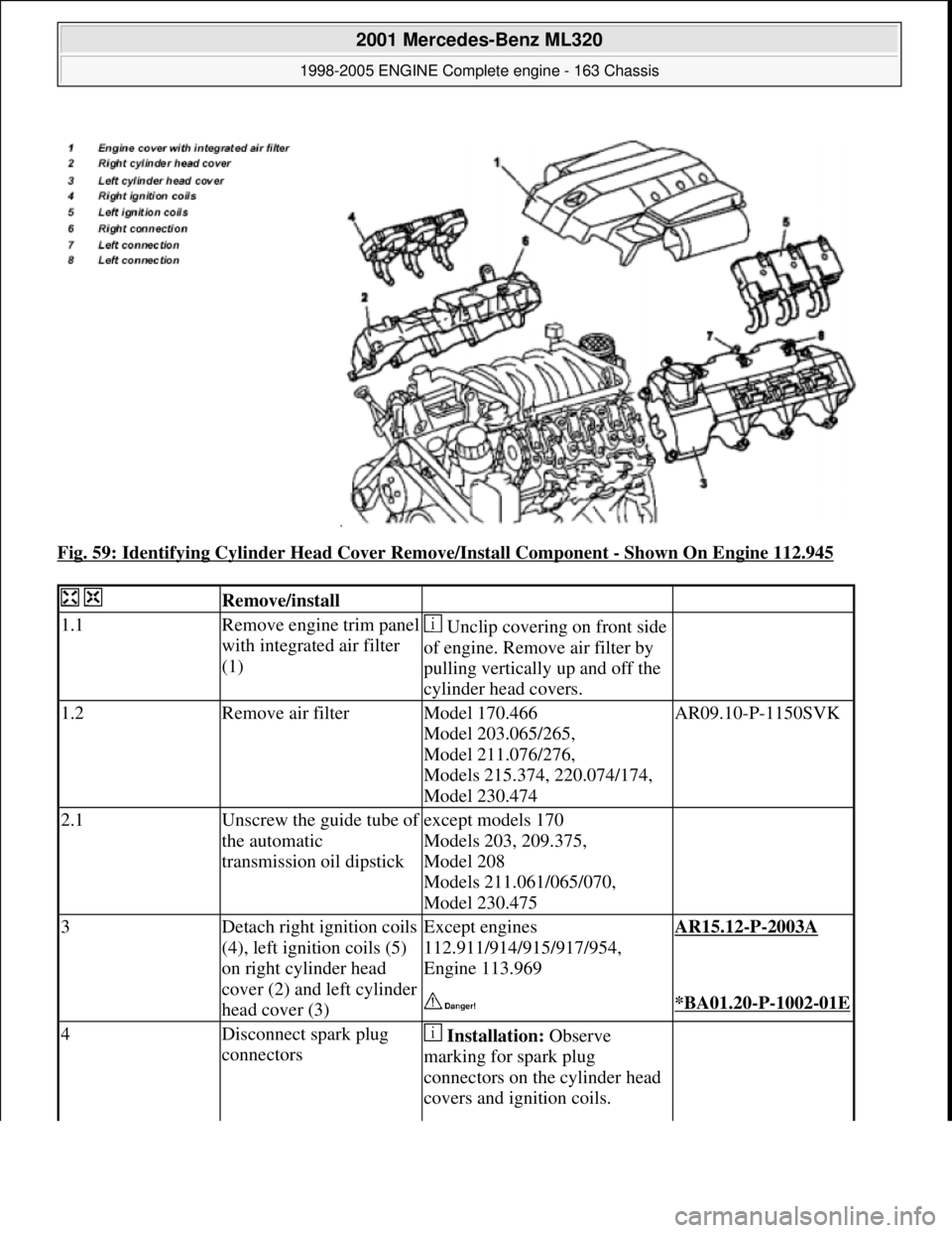
Fig. 59: Identifying Cylinder Head Cover Remove/Install Component - Shown On Engine 112.945
Remove/install
1.1Remove engine trim panel
with integrated air filter
(1) Unclip covering on front side
of engine. Remove air filter by
pulling vertically up and off the
cylinder head covers.
1.2Remove air filterModel 170.466
Model 203.065/265,
Model 211.076/276,
Models 215.374, 220.074/174,
Model 230.474AR09.10-P-1150SVK
2.1Unscrew the guide tube of
the automatic
transmission oil dipstickexcept models 170
Models 203, 209.375,
Model 208
Models 211.061/065/070,
Model 230.475
3Detach right ignition coils
(4), left ignition coils (5)
on right cylinder head
cover (2) and left cylinder
head cover (3)Except engines
112.911/914/915/917/954,
Engine 113.969AR15.12-P-2003A
*BA01.20-P-1002-01E
4Disconnect spark plug
connectors Installation: Observe
marking for spark plug
connectors on the cylinder head
covers and ignition coils.
2001 Mercedes-Benz ML320
1998-2005 ENGINE Complete engine - 163 Chassis
me
Saturday, October 02, 2010 3:17:56 PMPage 67 © 2006 Mitchell Repair Information Company, LLC.
Page 2425 of 4133

Crankcase ventilation, cylinder head cover
Fuel rail
Fuel rail
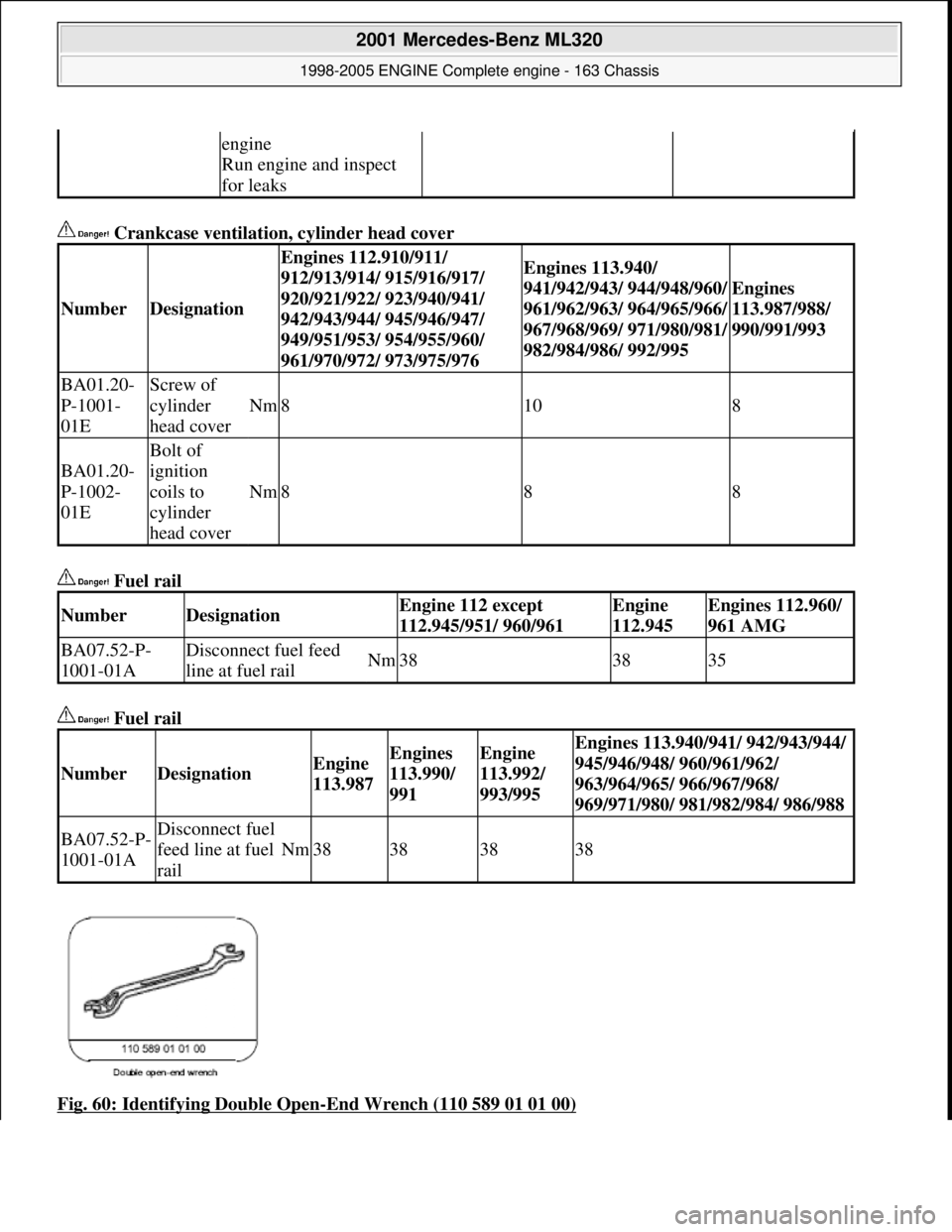
Fig. 60: Identifying Double Open
-End Wrench (110 589 01 01 00)
engine
Run engine and inspect
for leaks
NumberDesignation
Engines 112.910/911/
912/913/914/ 915/916/917/
920/921/922/ 923/940/941/
942/943/944/ 945/946/947/
949/951/953/ 954/955/960/
961/970/972/ 973/975/976Engines 113.940/
941/942/943/ 944/948/960/
961/962/963/ 964/965/966/
967/968/969/ 971/980/981/
982/984/986/ 992/995
Engines
113.987/988/
990/991/993
BA01.20-
P-1001-
01EScrew of
cylinder
head cover
Nm8108
BA01.20-
P-1002-
01E
Bolt of
ignition
coils to
cylinder
head cover
Nm888
NumberDesignationEngine 112 except
112.945/951/ 960/961Engine
112.945Engines 112.960/
961 AMG
BA07.52-P-
1001-01ADisconnect fuel feed
line at fuel railNm383835
NumberDesignationEngine
113.987Engines
113.990/
991Engine
113.992/
993/995Engines 113.940/941/ 942/943/944/
945/946/948/ 960/961/962/
963/964/965/ 966/967/968/
969/971/980/ 981/982/984/ 986/988
BA07.52-P-
1001-01ADisconnect fuel
feed line at fuel
rail
Nm38383838
2001 Mercedes-Benz ML320
1998-2005 ENGINE Complete engine - 163 Chassis
me
Saturday, October 02, 2010 3:17:56 PMPage 69 © 2006 Mitchell Repair Information Company, LLC.
Page 2426 of 4133
Fig. 61: Identifying Pressure Hose (119 589 04 63 00)
TAP THREAD IN SPARK PLUG HOLE AND SCRE W IN THREADED INSERT - AR01.30-P-5440-01B
Fig. 62: Identifying Heli-Coil Repair Set (102 589 00 99 00)
1. Remove pilot bushing (1) of tapped hole device .
2. Fill the swarf grooves of the combination tap (4) with grease for bonding the swarfs.
3. Cut combination tap (4) into corresponding spark pl ug thread. Screw in combination tap (4) until the
guide tube (3) is seated and forms a fully compress with the stop ring (2).
Screw out after 5 revolutions on removed cylinder head combination tap (4), clean the swarf grooves
from swarfs and grease, refi ll with grease and finish cutting thread. After cutting.
Blow out spark plu
g thread and cylinder with compressed air.
2001 Mercedes-Benz ML320
1998-2005 ENGINE Complete engine - 163 Chassis
me
Saturday, October 02, 2010 3:17:56 PMPage 70 © 2006 Mitchell Repair Information Company, LLC.
Page 2427 of 4133
Fig. 63: Identifying Pilot Bushing, Stop Ring, Guide Tube And Combination Tap
4. Select heli-coil threaded inse rt (8) with block length 10.2 mm.
5. Insert threaded insert (8) with primary pump drive pointing in direction of prestessing cartridge (16) in
the installation tool (13) (arrow).
6. Screw in threaded insert (8) flush to prestessing cartridge (16) (arrow).
Fig. 64: Identifying Installation T ool, Threaded Insert And Cartridge
7. Position HC-installat ion tool on tapped hole
2001 Mercedes-Benz ML320
1998-2005 ENGINE Complete engine - 163 Chassis
me
Saturday, October 02, 2010 3:17:56 PMPage 71 © 2006 Mitchell Repair Information Company, LLC.
Page 2428 of 4133
8. Hold jacket sleeve (5)
9. Rotate screw-in spindle (6) until the stop ring (7) is pos itioned on the jacket sleeve (5). Slightly turn back
a clamping jacket sleeve when screwing-in.
Fig. 65: Identifying Jacket Sleeve, Spindle And Stop Ring
10. Insert sleeve (9) via primary pum p drive of HELI-COIL insert
11. Guide open pliers to the marking in the sleeve (9) and fix with primary pump drive
12. Close pliers , the serrated lock of pliers must latch.
13. Rotate sleeve (9) toward left as far as the stop and hold
14. Dismount primary pump drive, to do so move pliers slightly up and down.
Remove with a ma
gnet the primary pump drive which had fallen onto the piston crown!
2001 Mercedes-Benz ML320
1998-2005 ENGINE Complete engine - 163 Chassis
me
Saturday, October 02, 2010 3:17:56 PMPage 72 © 2006 Mitchell Repair Information Company, LLC.
Page 2429 of 4133
Fig. 66: Identifying Sleeve & Pliers
CAULK THREADED INSE RT - AR01.30-P-5440-02B
Fig. 67: Identifying Heli-Coil Repair Set (102 589 00 99 00)
1. Grease caulk drift, screw into installed HELI-COI L insert and tighten with a torque of approx. 25-30
Nm.
2001 Mercedes-Benz ML320
1998-2005 ENGINE Complete engine - 163 Chassis
me
Saturday, October 02, 2010 3:17:56 PMPage 73 © 2006 Mitchell Repair Information Company, LLC.
Page 2433 of 4133

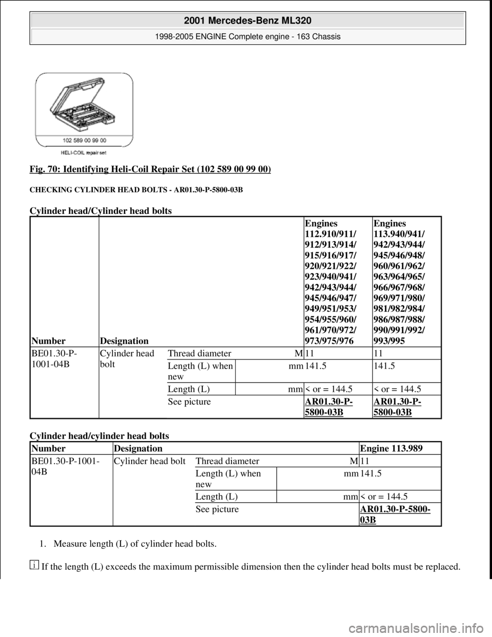
Fig. 70: Identifying Heli-Coil Repair Set (102 589 00 99 00)
CHECKING CYLINDER HEAD BOLTS - AR01.30-P-5800-03B
Cylinder head/Cylinder head bolts
Cylinder head/cyl inder head bolts
1. Measure length (L) of cylinder head bolts.
If the length (L) exceeds the maximu m permissible dimension then the cyli nder head bolts must be replaced.
NumberDesignation
Engines
112.910/911/
912/913/914/
915/916/917/
920/921/922/
923/940/941/
942/943/944/
945/946/947/
949/951/953/
954/955/960/
961/970/972/
973/975/976Engines
113.940/941/
942/943/944/
945/946/948/
960/961/962/
963/964/965/
966/967/968/
969/971/980/
981/982/984/
986/987/988/
990/991/992/
993/995
BE01.30-P-
1001-04BCylinder head
boltThread diameterM1111
Length (L) when
newmm141.5141.5
Length (L)mm< or = 144.5< or = 144.5
See pictureAR01.30-P-
5800-03B
AR01.30-P-
5800-03B
NumberDesignationEngine 113.989
BE01.30-P-1001-
04BCylinder head boltThread diameterM11
Length (L) when
newmm141.5
Length (L)mm< or = 144.5
See pictureAR01.30-P-5800-
03B
2001 Mercedes-Benz ML320
1998-2005 ENGINE Complete engine - 163 Chassis
me
Saturday, October 02, 2010 3:17:56 PMPage 77 © 2006 Mitchell Repair Information Company, LLC.
Page 2443 of 4133

*BA07.52-P-
1001-01A
Pressure hoseFig. 52
12Remove right and
left ignition coils
(12) AR15.12-P-
2003A
13Remove right and
left cylinder head
covers (13) AR01.20-P-
5014B
14Remove intake
manifold (14) Installation: On vehicles with engine
damage, the intake manifold must be examined
for swarfs before assembling and any swarfs
present must be removed, in order to avoid
consequential damage.
The intake manifold system must not be
disassembled.
Remove intake manifold together with fuel
distributor.AR09.20-P-
1310A
15.1Remove camshaft
angle position sensor
(15) Only necessary if right cylinder head is
removed.AR15.10-P-
2000A
16Remove poly-V-belt
(8) Installation: Lock tensioning device with a
drift or pin (diameter 5 mm).
Models 163.154/157/172.AR13.22-P-
1202B
Models 163.174/175.AR13.22-P-
1202BA
17Detach coolant line
(16) at left cylinder
head 6 mm socket hexagon*WH58.30-Z-
1001-06A
7 mm socket hexagon*WH58.30-Z-
1002-06A
18.1Remove inner fender
(9) Only for engine 113.942 /965 /981.AR88.10-P-
1300GH
19.1Remove shield (10) Only for engine 113.942 /965 /981.
20.1Remove exhaust
bracket (11) Only for engine 113.942 /965 /981.
Support exhaust system.
21Detach exhaust
system at exhaust
manifold Installation: On vehicles with engine
damage check exhaust sy stem for chips before
assembly and remove any chips present to
prevent later damage
*BA14.10-P-
1002-01B
22Position crankshaft
to 40° after ignition The engine must not be turned back;
otherwise the timing chain can get jammed. AR05.10-P-
6858V
2001 Mercedes-Benz ML320
1998-2005 ENGINE Complete engine - 163 Chassis
me
Saturday, October 02, 2010 3:17:57 PMPage 87 © 2006 Mitchell Repair Information Company, LLC.