1997 MERCEDES-BENZ ML500 oil
[x] Cancel search: oilPage 2855 of 4133
An excess oil level or insufficient oil level appears in the display together with the oil can symbol.
Display of low oil level at maximum:
at driver request
Display of warnings:
automatically, at the earliest 60s after engine start and oil temperature greater than 60°C:
if oil level too high: the oil can symbol appears together with the readout "OIL LEVEL ABOVE
MAX". In addition, a brief warning signal sounds. (On models not fitted with multifunction
display, "HI" appears flashing.)
if oil level too low: the oil can symbol appears together with the readout "OIL LEVEL BELOW
MIN". In addition, a brief warning signal sounds. (On models not fitted with multifunction display,
the oil level warning lamp (A1e12) comes on and the readout "-2L" appears flashing.)
if oil at minimum: the oil can symbol appears together with the readout "OIL LEVEL MINIMUM".
In addition, a brief warning signal sounds. (On models not fitted with multifunction display, the oil
level warning lamp (A1e12) comes on.)
automatically 13 s after ignition ON:
if no oil is in engine: the oil can symbol appears together with the readout "OIL LEVEL BELOW
MIN". In addition, a warning signal sounds. (On models not fitted with multifunction display, the
oil level warning lamp (A1e12) comes on and the readout "-2L" appears flashing. In addition a
brief warning signal sounds.)
The missing oil quantity displayed no longer changes during the display. In other words, any change in oil level
cannot be observed directly at the display. The new oil level is only displayed once the conditions described
below exist.
Display of oil quantity at driver request
The text "DISPLAY OIL LEVEL?" appears 10 s after the start switch has been turned into position "2" (on
models not fitted with multifunction display, the oil can and the clock symbol are displayed).
If the reset button of the trip counter is pressed twice within one sec. during this readout, for example, "add 1.0L
oil" (or "-1.0L")
appears in the display if oil level too low. The readout appears only after the elapse of a waiting time after
engine OFF. The waiting time depends on the engine oil temperature.
It is
up to 20°C 30 minutes
from 60°C 1 minute
The waiting time is between these two limits at other engine oil temperatures.
2004 Mercedes-Benz ML350
1998-2005 GENINFO Overall vehicle - 163 Chassis
me
Saturday, October 02, 2010 3:47:47 PMPage 210 © 2006 Mitchell Repair Information Company, LLC.
Page 2856 of 4133
Possible readouts are (text in parenthesis relates to models not fitted with multifunction display.):
"OIL LEVEL OKAY" ("o.k."),
1.0L, 1.5L, 2L,
"Overfilling" ("HI"),
"OBSERVE WAITING TIME" (clock symbol flashing and oil can symbol),
"DISPLAY OIL LEVEL" (clock and oil can symbols.)
If there is a fault at the oil sensor (oil level/temperature/quality, B40) the oil can symbol and the text "OIL
LEVEL SENSOR FAULTY" appears only 30 s after the fault has occurred.
(On models not fitted with multifunction display, the oil level warning lamp (A1e12) comes on accordingly.)
For diagnosis, read also the injection system control module (N3) with the HHT. (The instrument cluster (A1)
receives the sensor data through the CAN from the injection system control module (N3)).
Oil change
The ASSYST has to be reset each time the oil is changed. Resetting ASSYST also resets the remaining time and
the remaining distance. Resetting can be performed at the instrument cluster or using the HHT. The following
data are stored when the system is reset:
current kilometer reading rounded off to 100,
total oil replenishments in the last interval,
remaining distance,
remaining time,
product of the quality factors,
the data of the last 5 resettings in 5 data sets
These data can only be read with the HHT!
If the specified quantity of oil is not replenished when the oil is changed, the (internal) start distance is
reduced.
Detecting oil replenishments
With the HHT it is possible to retrieve the last 10 oil replenishments and the corresponding kilometer
readings of the current interval.
In the normal case, detection of an oil replenishment is displayed by the remaining distance in the
instrument cluster being extended
Oil replenishments are always only detected once the following conditions are met:
the replenished quantit
y is at least
2004 Mercedes-Benz ML350
1998-2005 GENINFO Overall vehicle - 163 Chassis
me
Saturday, October 02, 2010 3:47:47 PMPage 211 © 2006 Mitchell Repair Information Company, LLC.
Page 2857 of 4133
In the charts overleaf, a number of examples of this are presented. The horizontal (x) axis represents the service
interval and the vertical (y) axis is the remaining distance in each case in km.
conditions are met:
the replenished quantity is at least 1 l
after replenishing the oil, the car must be driven a distance of at least 5 km under normal driving
conditions at an oil temperature of at least 60°C
There are instances, however, in which the readout of the remaining distance nevertheless appears implausible
after replenishing oil; according to the display, no bonus or only a small bonus has been issued. This is caused
by the fact that the remaining distance is always only displayed within a range from 15 000 km up to 30 000 km
(or 20 000 km up to 40 000 km in the case of engine 668), but internally the system calculates with the actual
values which may also be beyond this range. These internal values can only be displayed with the HHT.
horizontal (x) axis represents the service interval and the vertical (y) axis is the remaining distance in each case
in km.
The readout of ASSYST in the instrument cluster always moves within the light range.
The remaining distance calculated internally may also, however, be within the two dark ranges. These internal
values can only be displayed with the HHT.
All examples relate to gasoline engines fitted with an oil sensor.
Example 1 :
Sufficient oil was added during the oil change. This means that the starting distance is 15 000 km.
After 10 000 km oil is topped up under normal driving conditions (a). The bonus (B1) is issued and displayed.
What this means is that when the remaining distance is retrieved, a greater remaining distance is displayed.
(Provided the aforementioned conditions for detecting the oil replenishment are met.)
Oil is topped up again after a further 5 000 km (b). In this case also a bonus (B2) is issued and displayed.
If, after this, no further oil is topped up and the car continues to be driven in the same manner, a service interval
of about 24 000 km is thus achieved.
In this example, the curve moves at all points within the light range of the chart; consequently, all the oil
replenishments are displayed by increasing the remaining distance.
2004 Mercedes-Benz ML350
1998-2005 GENINFO Overall vehicle - 163 Chassis
me
Saturday, October 02, 2010 3:47:47 PMPage 212 © 2006 Mitchell Repair Information Company, LLC.
Page 2858 of 4133
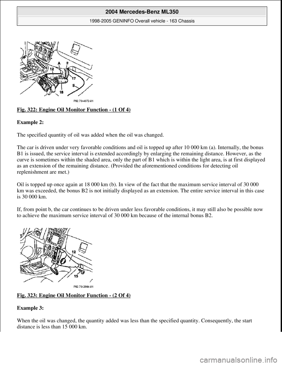
Fig. 322: Engine Oil Monitor Function - (1 Of 4)
Example 2:
The specified quantity of oil was added when the oil was changed.
The car is driven under very favorable conditions and oil is topped up after 10 000 km (a). Internally, the bonus
B1 is issued, the service interval is extended accordi ngly by enlarging the remaining distance. However, as the
curve is sometimes within the shaded ar ea, only the part of B1 which is within the light area, is at first displayed
as an extension of the remaining distance. (Provi ded the aforementioned conditions for detecting oil
replenishment are met.)
Oil is topped up once again at 18 000 km (b ). In view of the fact that the maximum service interval of 30 000
km was exceeded, the bonus B2 is not initially displayed as an extension. Th e entire service interval in this case
is 30 000 km.
If, from point b, the car continues to be driven under less favorable conditions , it may still also be possible now
to achieve the maximum service interval of 30 000 km because of the internal bonus B2.
Fig. 323: Engine Oil Monitor Function
- (2 Of 4)
Example 3:
When the oil was changed, the quantity added was less than the specified quantity. Consequently, the start
distance is less than 15 000 km.
2004 Mercedes-Benz ML350
1998-2005 GENINFO Overall vehicle - 163 Chassis
me
Saturday, October 02, 2010 3:47:47 PMPage 213 © 2006 Mitchell Repair Information Company, LLC.
Page 2859 of 4133
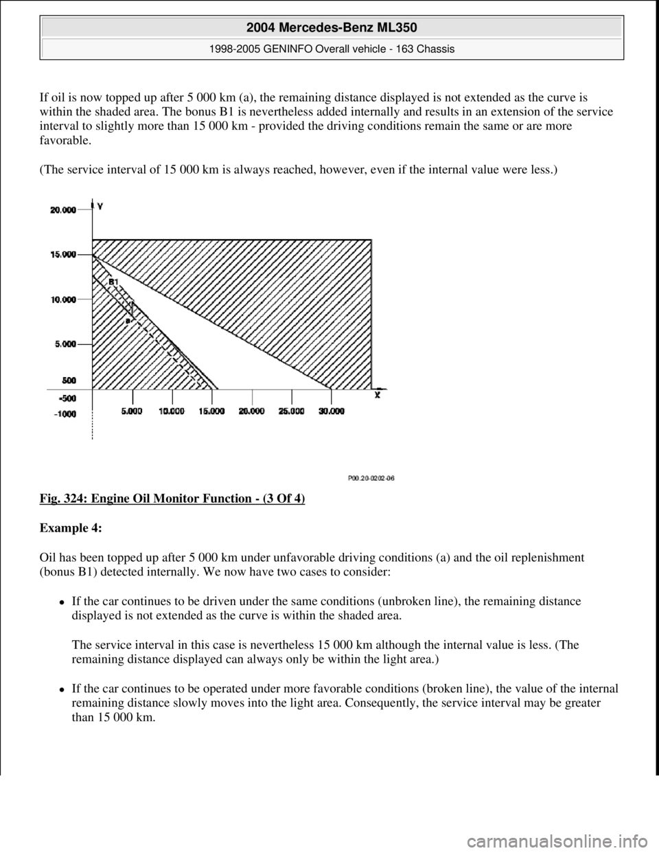
If oil is now topped up after 5 000 km (a), the remaining distance displayed is not extended as the curve is
within the shaded area. The bonus B1 is nevertheless added internally and results in an extension of the service
interval to slightly more than 15 000 km - provided the driving conditions remain the same or are more
favorable.
(The service interval of 15 000 km is always reached, however, even if the internal value were less.)
Fig. 324: Engine Oil Monitor Function
- (3 Of 4)
Example 4:
Oil has been topped up after 5 000 km under unfavorable driving conditions (a) and the oil replenishment
(bonus B1) detected internally. We now have two cases to consider:
If the car continues to be driven under the same conditions (unbroken line), the remaining distance
displayed is not extended as the curve is within the shaded area.
The service interval in this case is nevertheless 15 000 km although the internal value is less. (The
remaining distance displayed can always only be within the light area.)
If the car continues to be operated under more favorable conditions (broken line), the value of the internal
remaining distance slowly moves into the light area. Consequently, the service interval may be greater
than 15 000 km.
2004 Mercedes-Benz ML350
1998-2005 GENINFO Overall vehicle - 163 Chassis
me
Saturday, October 02, 2010 3:47:47 PMPage 214 © 2006 Mitchell Repair Information Company, LLC.
Page 2860 of 4133
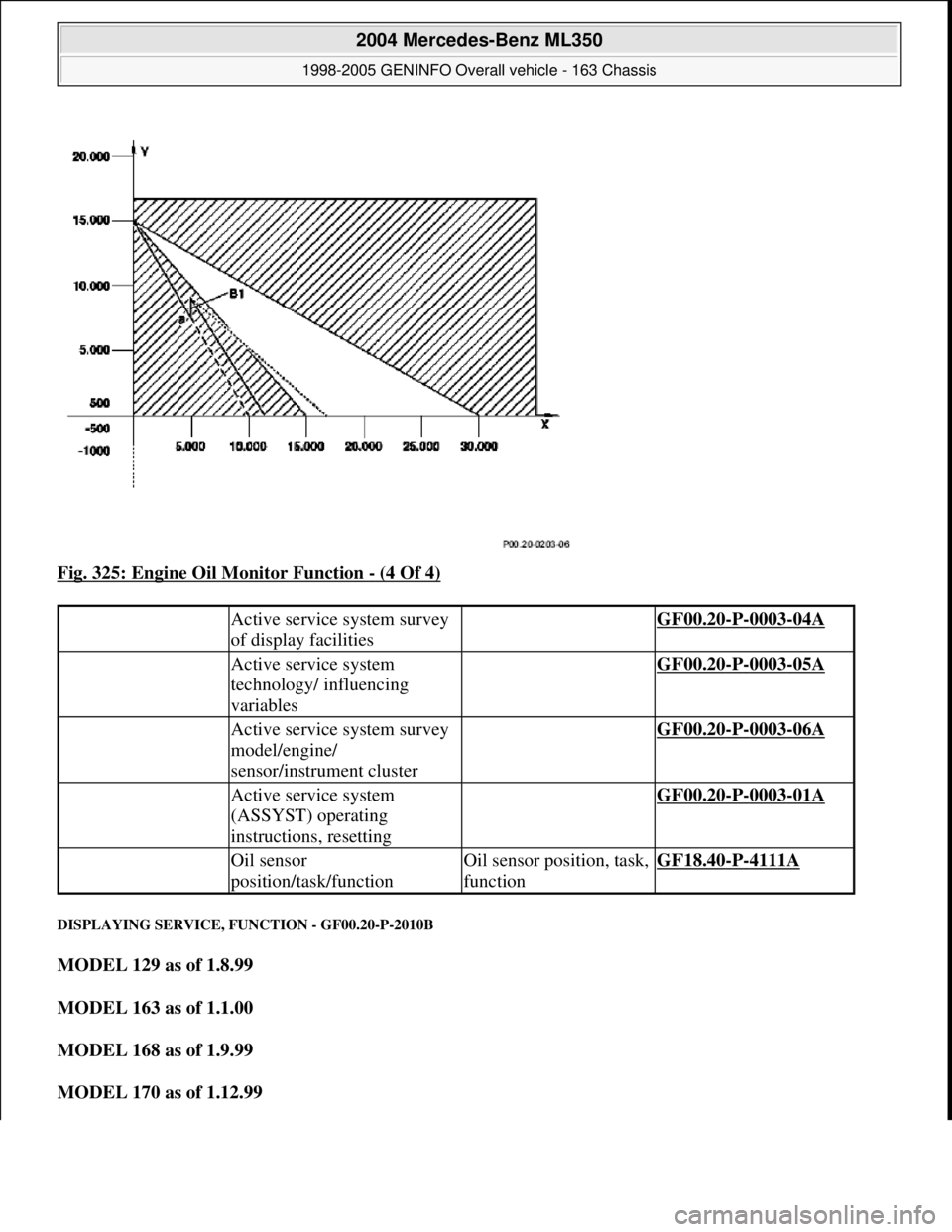
Fig. 325: Engine Oil Monitor Function - (4 Of 4)
DISPLAYING SERVICE, FUNCTION - GF00.20-P-2010B
MODEL 129 as of 1.8.99
MODEL 163 as of 1.1.00
MODEL 168 as of 1.9.99
MODEL 170 as of 1.12.99
Active service system survey
of display facilities GF00.20-P-0003-04A
Active service system
technology/ influencing
variables GF00.20-P-0003-05A
Active service system survey
model/engine/
sensor/instrument cluster GF00.20-P-0003-06A
Active service system
(ASSYST) operating
instructions, resetting GF00.20-P-0003-01A
Oil sensor
position/task/functionOil sensor position, task,
functionGF18.40-P-4111A
2004 Mercedes-Benz ML350
1998-2005 GENINFO Overall vehicle - 163 Chassis
me
Saturday, October 02, 2010 3:47:47 PMPage 215 © 2006 Mitchell Repair Information Company, LLC.
Page 2862 of 4133
RISK OF INJURY CAUSED BY PINCHING OR JAMMING WHEN WORKING ON LOADED SPRINGS OR SPRING BODIES
- AS00.00-Z-0001-01A
Use only approved clamping devices; shield off hazard area if necessary. Inspect special tools for damage
and proper operation (visual inspection). Wear protective gloves.
Risk of pinching and jamming body parts when working on pre-loaded components.
When loosening or removing components that are under significant load, there is a risk of serious injury if
non-approved if clamping devices are used.
Safety instructions/precautions
When conducting repair work on springs, spring bodies, spring-type actuators and other components under
tension use approved clamping devices only .
Spring compressor
The spring compressor should never be clamped or released using an impact wrench.
Check clamping devices
The spindle must be undamaged and allow ease of movement.
The clamping plates must not be deformed.
Note arrangement of clamping plates to springs.
If the device is damaged or malfunctioning, it must be returned to the manufacturer.
The coil diameter of the spring should match the groove in the clamping plate.
Wear protective gloves during all operations.
RISK OF INJURY. SKIN OR EYE INJURIES MAY RESULT WHEN HANDLING HOT OR GLOWING OBJECTS. - AS00.00-
Z-0002-01A
Wear protective gloves, protective clothing and (where necessary) safety glasses.
Risk of injury
Unprotected contact with hot or glowing objects may cause severe burns to the skin and eyes.
If glowing objects come into contact with water, hot steam or hot splashing water may result in severe skin and
eye burns.
Severe and possibly permanent injuries may result if hot or glowing objects come into contact with unprotected
skin or eyes.
Fire ma
y result if glowing objects come into contact with flammable materials or substances.
2004 Mercedes-Benz ML350
1998-2005 GENINFO Overall vehicle - 163 Chassis
me
Saturday, October 02, 2010 3:47:47 PMPage 217 © 2006 Mitchell Repair Information Company, LLC.
Page 2883 of 4133
![MERCEDES-BENZ ML500 1997 Complete Repair Manual MODELS 124, 129, 140, 163 up to 30.11.99, 163 as of 1.9.01, 168, 170, 201, 202, 208, 210, 215, 220
EXPLANATION OF SYMBOLS FOR TESTERS AND COMPONENTS - AD00.00-P-2000-01A
0.0 [] 1Key to diagnostics
s MERCEDES-BENZ ML500 1997 Complete Repair Manual MODELS 124, 129, 140, 163 up to 30.11.99, 163 as of 1.9.01, 168, 170, 201, 202, 208, 210, 215, 220
EXPLANATION OF SYMBOLS FOR TESTERS AND COMPONENTS - AD00.00-P-2000-01A
0.0 [] 1Key to diagnostics
s](/manual-img/4/57308/w960_57308-2882.png)
MODELS 124, 129, 140, 163 up to 30.11.99, 163 as of 1.9.01, 168, 170, 201, 202, 208, 210, 215, 220
EXPLANATION OF SYMBOLS FOR TESTERS AND COMPONENTS - AD00.00-P-2000-01A
0.0 [] 1Key to diagnostics
symbols AD00.00-P-2001A
0.0 [] 2Diagnosis assignmentexcept models 215, 220AD00.00-P-2002A
0.0 [] 3Connect test equipment
diagnosisexcept model 215AD00.00-P-2003A
0.0 [] 4Diagnostic procedureonly for vehicle systems
that can be diagnosed using
STAR DIAGNOSISAD00.00-P-2004A
DescriptionLogoDescriptionLogoDescriptionLogo
ABS Adapter Battery Short-circuit
35-pin socket
box Direct current
generator Short-circuit to
ground
126-pin socket
box Direct current
motor Open-circuit
Function
generator Capacitor Multimeter
alternating
voltage type of
measurement
Hand-Held
Tester Coil Multimeter
resistance type of
measurement
Pulse counter Resistance Function
generator square-
wave signal shape
Lambda control
tester Ground Function
generator
sinusoidal signal
shape
Pressure gauge In order Oscilloscope
Multimeter Fault Adapter cable
with light-
emitting diode
Decade resistor Greater than > Multimeter direct
current type of
measurement
Bridge Less than < Multimeter
alternating
current type of
measurement
2004 Mercedes-Benz ML350
1998-2005 GENINFO Overall vehicle - 163 Chassis
me
Saturday, October 02, 2010 3:47:48 PMPage 238 © 2006 Mitchell Repair Information Company, LLC.