1997 MERCEDES-BENZ ML500 oil
[x] Cancel search: oilPage 1657 of 4133
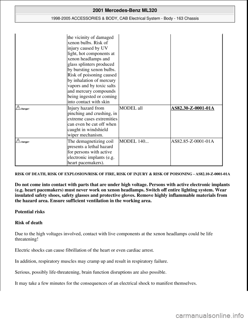
RISK OF DEATH, RISK OF EXPLOSION/RISK OF FIRE, RISK OF INJURY & RISK OF POISONING - AS82.10-Z-0001-01A
Do not come into contact with parts that are under high voltage. Persons with active electronic implants
(e.g. heart pacemakers) must never work on xenon headlamps. Switch off entire lighting system. Wear
insulated safety shoes, safety glasses and protective gloves. Remove highly inflammable materials from
the hazard area. Ensure sufficient ventilation in the working area.
Potential risks
Risk of death
Due to the high voltages involved, contact with live components at the xenon headlamps could be life
threatening!
Electric shocks can cause fibrillation of the heart or even cardiac arrest.
In addition, respiratory muscles may cramp up and result in respiratory failure.
Serious, possibly life-threatening, brain function disruptions are also possible.
It ma
y take a few minutes for the consequences of an electrical shock to manifest themselves.
the vicinity of damaged
xenon bulbs. Risk of
injury caused by UV
light, hot components at
xenon headlamps and
glass splinters produced
by bursting xenon bulbs.
Risk of poisoning caused
by inhalation of mercury
vapors and by toxic salts
and mercury compounds
being ingested or coming
into contact with skin
Injury hazard from
pinching and crushing, in
extreme cases extremities
can even be cut off when
caught in windshield
wiper mechanism.MODEL allAS82.30-Z-0001-01A
The demagnetizing coil
presents a lethal hazard
for persons with active
electronic implants (e.g.
heart pacemakers).MODEL 140...AS82.85-Z-0001-01A
2001 Mercedes-Benz ML320
1998-2005 ACCESSORIES & BODY, CAB Electrical System - Body - 163 Chassis
me
Saturday, October 02, 2010 3:30:06 PMPage 162 © 2006 Mitchell Repair Information Company, LLC.
Page 1665 of 4133
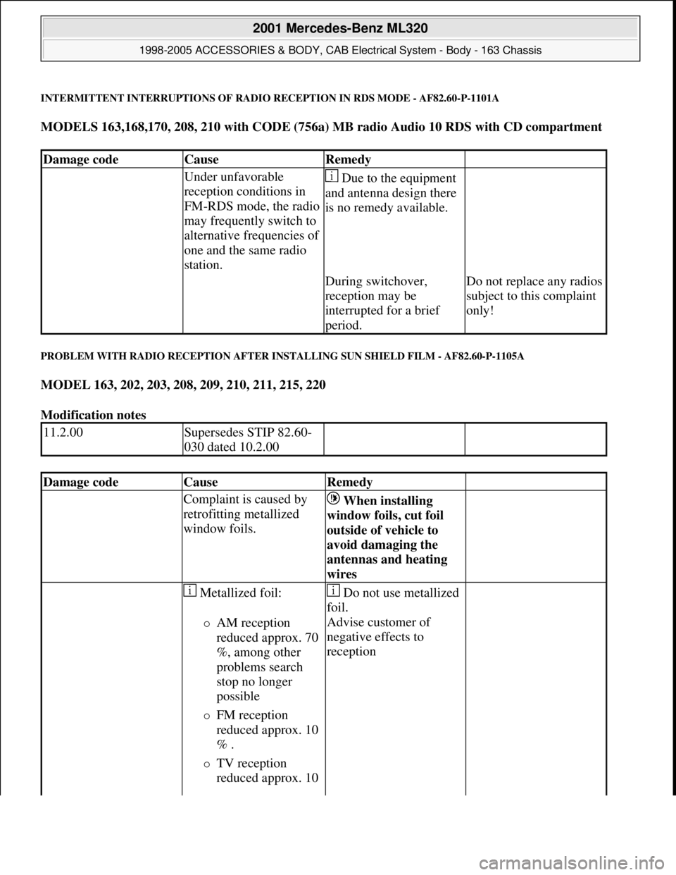
INTERMITTENT INTERRUPTIONS OF RADIO RECEPTION IN RDS MODE - AF82.60-P-1101A
MODELS 163,168,170, 208, 210 with CODE (756a) MB radio Audio 10 RDS with CD compartment
PROBLEM WITH RADIO RECEPTION AFTER INSTALLING SUN SHIELD FILM - AF82.60-P-1105A
MODEL 163, 202, 203, 208, 209, 210, 211, 215, 220
Modification notes
Damage codeCauseRemedy
Under unfavorable
reception conditions in
FM-RDS mode, the radio
may frequently switch to
alternative frequencies of
one and the same radio
station. Due to the equipment
and antenna design there
is no remedy available.
During switchover,
reception may be
interrupted for a brief
period.Do not replace any radios
subject to this complaint
only!
11.2.00Supersedes STIP 82.60-
030 dated 10.2.00
Damage codeCauseRemedy
Complaint is caused by
retrofitting metallized
window foils. When installing
window foils, cut foil
outside of vehicle to
avoid damaging the
antennas and heating
wires
Metallized foil:
AM reception
reduced approx. 70
%, among other
problems search
stop no longer
possible
FM reception
reduced approx. 10
% .
TV reception
reduced approx. 10
Do not use metallized
foil.
Advise customer of
negative effects to
reception
2001 Mercedes-Benz ML320
1998-2005 ACCESSORIES & BODY, CAB Electrical System - Body - 163 Chassis
me
Saturday, October 02, 2010 3:30:07 PMPage 170 © 2006 Mitchell Repair Information Company, LLC.
Page 1666 of 4133
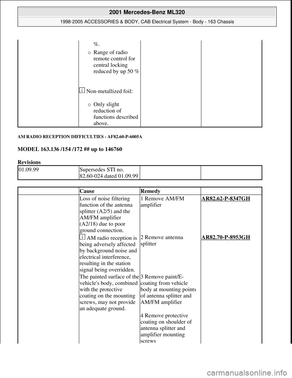
AM RADIO RECEPTION DIFFICULTIES - AF82.60-P-6005A
MODEL 163.136 /154 /172 ## up to 146760
Revisions
%.
Range of radio
remote control for
central locking
reduced by up 50 %
Non-metallized foil:
Only slight
reduction of
functions described
above.
01.09.99Supersedes STI no.
82.60-024 dated 01.09.99
CauseRemedy
Loss of noise filtering
function of the antenna
splitter (A2/5) and the
AM/FM amplifier
(A2/18) due to poor
ground connection.1 Remove AM/FM
amplifierAR82.62-P-8347GH
AM radio reception is
being adversely affected
by background noise and
electrical interference,
resulting in the station
signal being overridden.2 Remove antenna
splitterAR82.70-P-8953GH
The painted surface of the
vehicle's body, combined
with the protective
coating on the mounting
screws, may not provide
an adequate ground.3 Remove paint/E-
coating from vehicle
body at mounting points
of antenna splitter and
AM/FM amplifier
4 Remove protective
coating on shoulder of
antenna splitter and
amplifier mounting
screws
2001 Mercedes-Benz ML320
1998-2005 ACCESSORIES & BODY, CAB Electrical System - Body - 163 Chassis
me
Saturday, October 02, 2010 3:30:07 PMPage 171 © 2006 Mitchell Repair Information Company, LLC.
Page 1742 of 4133
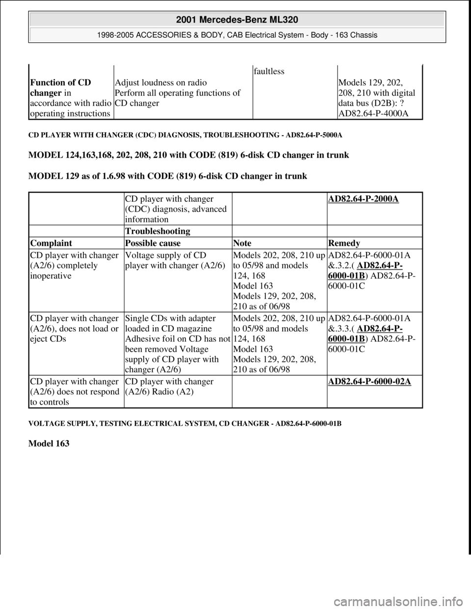
CD PLAYER WITH CHANGER (CDC) DIAGNOSIS, TROUBLESHOOTING - AD82.64-P-5000A
MODEL 124,163,168, 202, 208, 210 with CODE (819) 6-disk CD changer in trunk
MODEL 129 as of 1.6.98 with CODE (819) 6-disk CD changer in trunk
VOLTAGE SUPPLY, TESTING ELECTRICAL SYSTEM, CD CHANGER - AD82.64-P-6000-01B
Model 163
faultless
Function of CD
changer in
accordance with radio
operating instructionsAdjust loudness on radio
Perform all operating functions of
CD changer Models 129, 202,
208, 210 with digital
data bus (D2B): ?
AD82.64-P-4000A
CD player with changer
(CDC) diagnosis, advanced
information AD82.64-P-2000A
Troubleshooting
Complaint Possible cause Note Remedy
CD player with changer
(A2/6) completely
inoperativeVoltage supply of CD
player with changer (A2/6)Models 202, 208, 210 up
to 05/98 and models
124, 168
Model 163
Models 129, 202, 208,
210 as of 06/98AD82.64-P-6000-01A
&.3.2.( AD82.64
-P-
6000-01B) AD82.64-P-
6000-01C
CD player with changer
(A2/6), does not load or
eject CDsSingle CDs with adapter
loaded in CD magazine
Adhesive foil on CD has not
been removed Voltage
supply of CD player with
changer (A2/6)Models 202, 208, 210 up
to 05/98 and models
124, 168
Model 163
Models 129, 202, 208,
210 as of 06/98AD82.64-P-6000-01A
&.3.3.( AD82.64
-P-
6000-01B) AD82.64-P-
6000-01C
CD player with changer
(A2/6) does not respond
to controlsCD player with changer
(A2/6) Radio (A2) AD82.64-P-6000-02A
2001 Mercedes-Benz ML320
1998-2005 ACCESSORIES & BODY, CAB Electrical System - Body - 163 Chassis
me
Saturday, October 02, 2010 3:30:08 PMPage 247 © 2006 Mitchell Repair Information Company, LLC.
Page 1842 of 4133
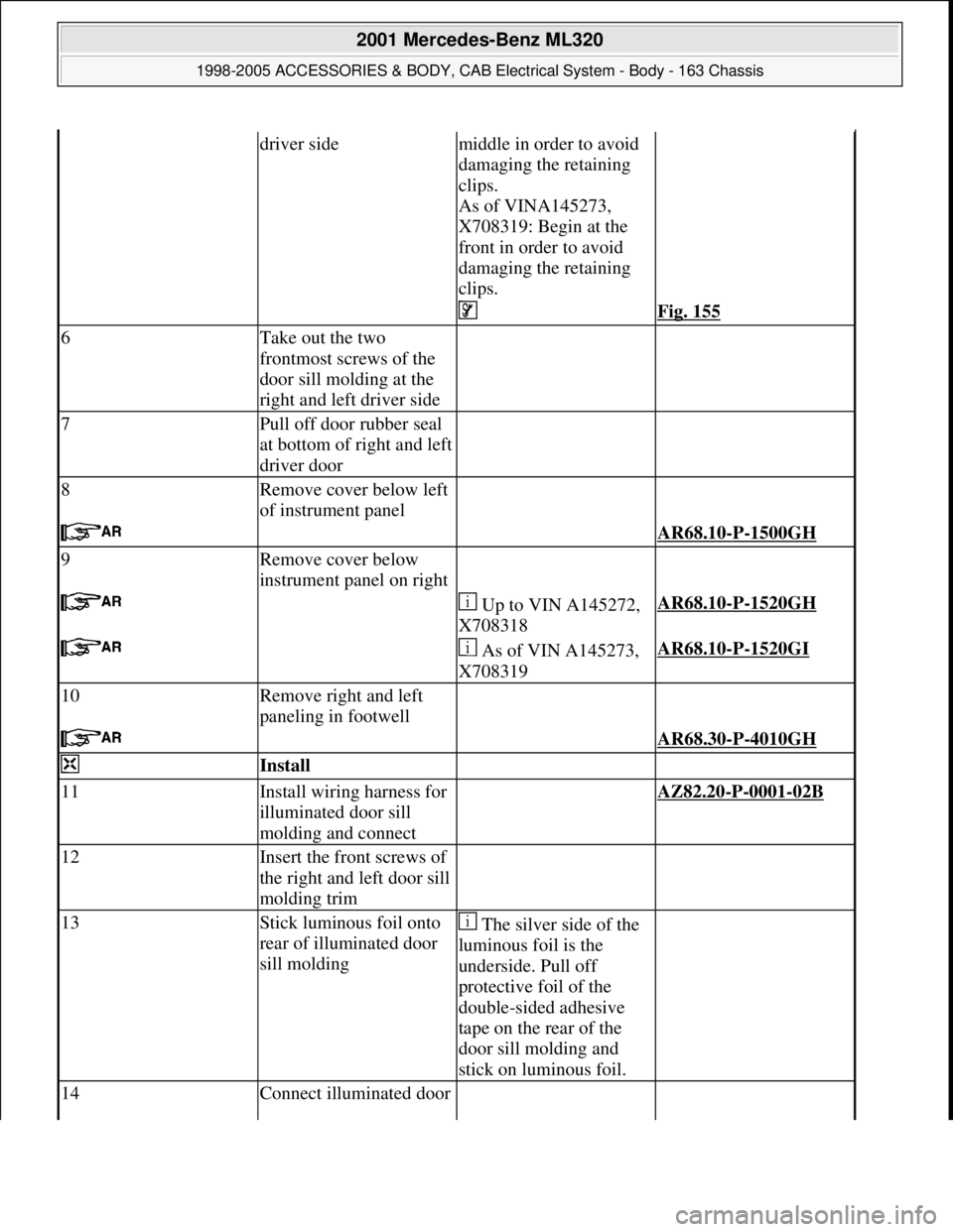
driver sidemiddle in order to avoid
damaging the retaining
clips.
As of VINA145273,
X708319: Begin at the
front in order to avoid
damaging the retaining
clips.
Fig. 155
6Take out the two
frontmost screws of the
door sill molding at the
right and left driver side
7Pull off door rubber seal
at bottom of right and left
driver door
8Remove cover below left
of instrument panel
AR68.10-P-1500GH
9Remove cover below
instrument panel on right
Up to VIN A145272,
X708318AR68.10-P-1520GH
As of VIN A145273,
X708319AR68.10-P-1520GI
10Remove right and left
paneling in footwell
AR68.30-P-4010GH
Install
11Install wiring harness for
illuminated door sill
molding and connect AZ82.20-P-0001-02B
12Insert the front screws of
the right and left door sill
molding trim
13Stick luminous foil onto
rear of illuminated door
sill molding The silver side of the
luminous foil is the
underside. Pull off
protective foil of the
double-sided adhesive
tape on the rear of the
door sill molding and
stick on luminous foil.
14Connect illuminated door
2001 Mercedes-Benz ML320
1998-2005 ACCESSORIES & BODY, CAB Electrical System - Body - 163 Chassis
me
Saturday, October 02, 2010 3:30:11 PMPage 347 © 2006 Mitchell Repair Information Company, LLC.
Page 1845 of 4133
If fitted.
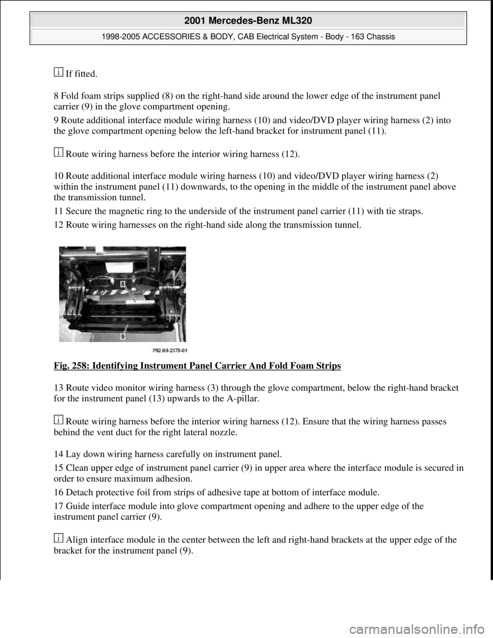
8 Fold foam strips supplied (8) on the right-hand side around the lower edge of the instrument panel
carrier (9) in the glove compartment opening.
9 Route additional interface module wiring harness (10) and video/DVD player wiring harness (2) into
the glove compartment opening below the left-hand bracket for instrument panel (11).
Route wiring harness before the interior wiring harness (12).
10 Route additional interface module wiring harness (10) and video/DVD player wiring harness (2)
within the instrument panel (11) downwards, to the opening in the middle of the instrument panel above
the transmission tunnel.
11 Secure the magnetic ring to the underside of the instrument panel carrier (11) with tie straps.
12 Route wiring harnesses on the right-hand side along the transmission tunnel.
Fig. 258: Identifying Instrument Panel Carrier And Fold Foam Strips
13 Route video monitor wiring harness (3) through the glove compartment, below the right-hand bracket
for the instrument panel (13) upwards to the A-pillar.
Route wiring harness before the interior wiring harness (12). Ensure that the wiring harness passes
behind the vent duct for the right lateral nozzle.
14 Lay down wiring harness carefully on instrument panel.
15 Clean upper edge of instrument panel carrier (9) in upper area where the interface module is secured in
order to ensure maximum adhesion.
16 Detach protective foil from strips of adhesive tape at bottom of interface module.
17 Guide interface module into glove compartment opening and adhere to the upper edge of the
instrument panel carrier (9).
Align interface module in the center between the left and right-hand brackets at the upper edge of the
bracket for the instrument panel (9).
2001 Mercedes-Benz ML320
1998-2005 ACCESSORIES & BODY, CAB Electrical System - Body - 163 Chassis
me
Saturday, October 02, 2010 3:30:11 PMPage 350 © 2006 Mitchell Repair Information Company, LLC.
Page 1849 of 4133
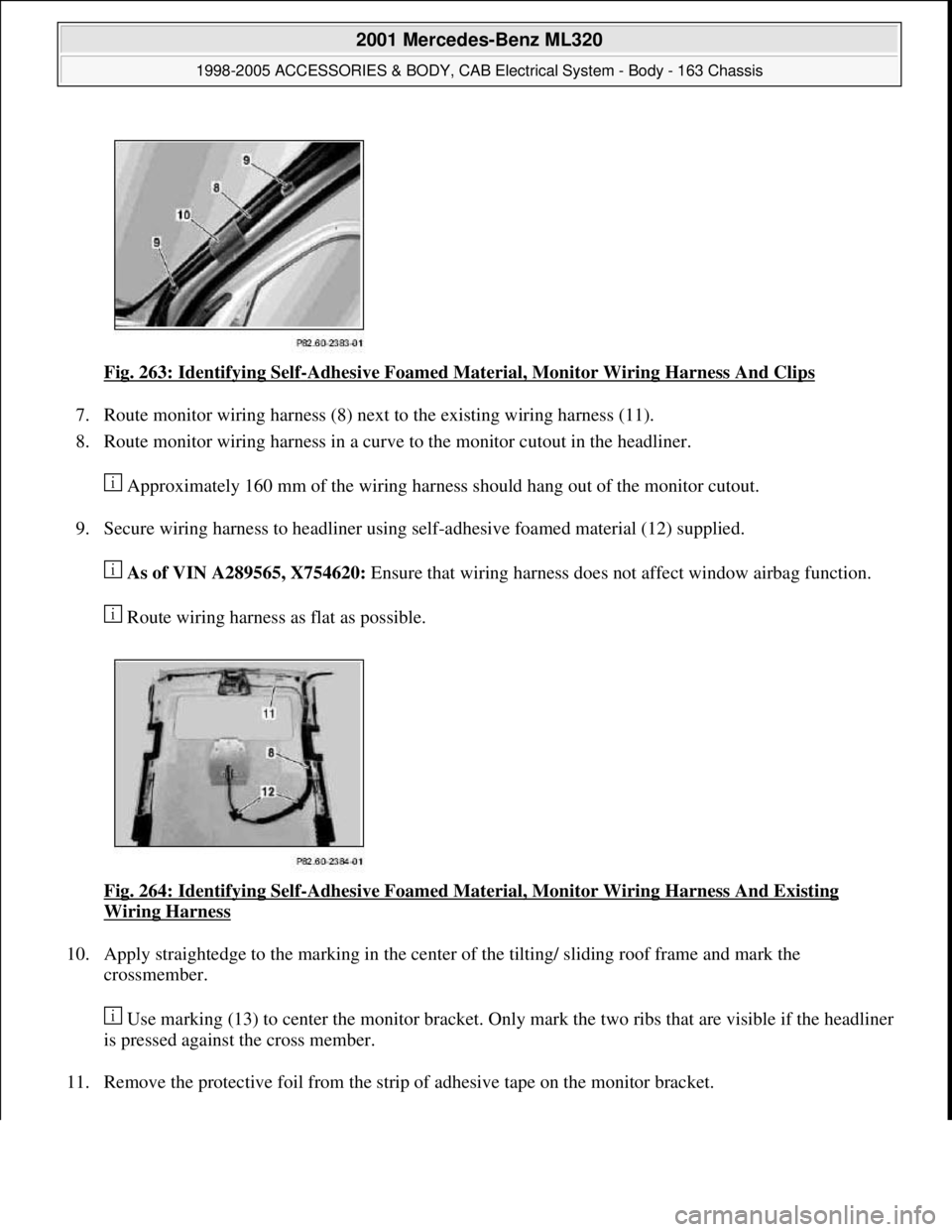
Fig. 263: Identifying Self-Adhesive Foamed Material, Monitor Wiring Harness And Clips
7. Route monitor wiring harness (8) next to the existing wiring harness (11).
8. Route monitor wiring harness in a curve to the monitor cutout in the headliner.
Approximately 160 mm of the wiring harness should hang out of the monitor cutout.
9. Secure wiring harness to headliner using self-adhesive foamed material (12) supplied.
As of VIN A289565, X754620: Ensure that wiring harness does not affect window airbag function.
Route wiring harness as flat as possible.
Fig. 264: Identifying Self
-Adhesive Foamed Material, Monitor Wiring Harness And Existing
Wiring Harness
10. Apply straightedge to the marking in the center of the tilting/ sliding roof frame and mark the
crossmember.
Use marking (13) to center the monitor bracket. Only mark the two ribs that are visible if the headliner
is pressed against the cross member.
11. Remove the protective foil from the strip of adhesive tape on the monitor bracket.
2001 Mercedes-Benz ML320
1998-2005 ACCESSORIES & BODY, CAB Electrical System - Body - 163 Chassis
me
Saturday, October 02, 2010 3:30:11 PMPage 354 © 2006 Mitchell Repair Information Company, LLC.
Page 1855 of 4133
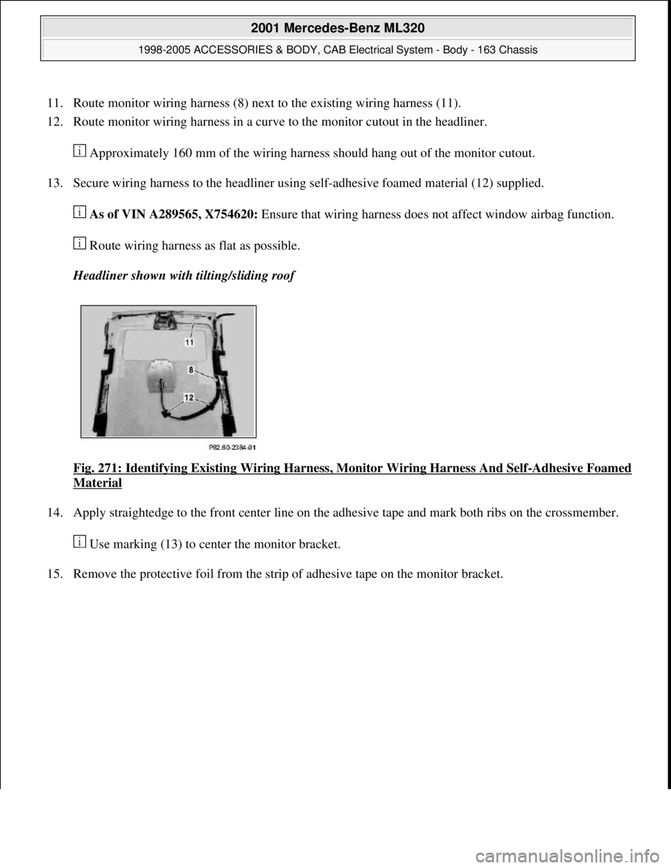
11. Route monitor wiring harness (8) next to the existing wiring harness (11).
12. Route monitor wiring harness in a curve to the monitor cutout in the headliner.
Approximately 160 mm of the wiring harness should hang out of the monitor cutout.
13. Secure wiring harness to the headliner using self-adhesive foamed material (12) supplied.
As of VIN A289565, X754620: Ensure that wiring harness does not affect window airbag function.
Route wiring harness as flat as possible.
Headliner shown with tilting/sliding roof
Fig. 271: Identifying Existing Wiring Harness, Monitor Wiring Harness And Self
-Adhesive Foamed
Material
14. Apply straightedge to the front center line on the adhesive tape and mark both ribs on the crossmember.
Use marking (13) to center the monitor bracket.
15. Remove the protective foil from the strip of adhesive tape on the monitor bracket.
2001 Mercedes-Benz ML320
1998-2005 ACCESSORIES & BODY, CAB Electrical System - Body - 163 Chassis
me
Saturday, October 02, 2010 3:30:11 PMPage 360 © 2006 Mitchell Repair Information Company, LLC.