1997 MERCEDES-BENZ ML500 oil
[x] Cancel search: oilPage 2105 of 4133

GF54.30-P-2002A
Display instruments, location / task / function
24.10.96
MODEL
129, 140 as of 1.6.96,
163, 168, 170,
202 as of 1.8.96,
208 up to 31.7.99,
210 as of 1.6.96 up to 30.6.99
Display
Type of data transmission
D
Outside temperature indicator (A1p4)
D
Fuel level gauge (A1p2)
D
Engine oil pressure gauge (A1p3), only
model 129 and model 140
D
Low windshield washer fluid level
indicator lamp (A1e13), model 163 as of
01.09.01
Direct lines
GF54.30-P-3004A
D
Total mileage odometer (A1h4)
D
Electronic speedometer (A1p8)
D
Tachometer (A1p5)
D
Coolant temperature gauge (A1p1)
D
Active service system (ASSYST)
D
Gear indicator (A1p12), only model 168
CAN data lines
GF54.30-P-3005A
D
Electronic clock
Internal
GF54.30-P-3011A
Copyright DaimlerChrysler AG 04.06.2006 CD-Ausgabe G/10/04 . This WIS print-out will not be recorde
d by Modification services.
Page 1
Page 2110 of 4133
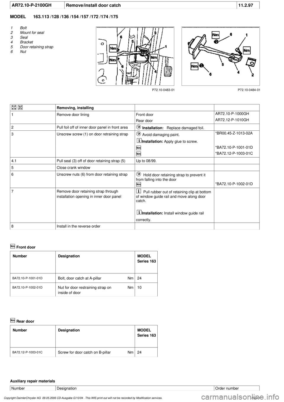
AR72.10-P-2100GH
Remove/install door catch
11.2.97
MODEL
163.113 /128 /136 /154 /157 /172 /174 /175
P72.10-0483-01
1
Bolt
2
Mount for seal
3
Seal
4
Bracket
5
Door retaining strap
6
Nut
P72.10-0484-01
Removing, installing
1
Remove door lining
Front door
AR72.10-P-1000GH
Rear door
AR72.12-P-1010GH
2
Pull foil off of inner door panel in front area
Installation:
Replace damaged foil.
3
Unscrew screw (1) on door retraining strap
Avoid damaging paint.
Installation:
Apply glue to screw.
*BR00.45-Z-1013-02A
*BA72.10-P-1001-01D
*BA72.12-P-1003-01C
4.1
Pull seal (3) off of door retaining strap (5)
Up to 08/99.
5
Close crank window
6
Unscrew nuts (6) from door retaining strap
Hold door retaining strap to prevent it
from falling into the door
*BA72.10-P-1002-01D
7
Remove door retaining strap through
installation opening in inner door panel
Pull rubber out of retaining clip at bottom
of window guide rail and move along door
catch.
Installation:
Install window guide rail
correctly.
8
Install in the reverse order
Front door
Number
Designation
MODEL
Series 163
BA72.10-P-1001-01DBolt, door catch at A-pillar
Nm
24
BA72.10-P-1002-01D
Nut for door restraining strap on
inside of door
Nm
10
Rear door
Number
Designation
MODEL
Series 163
BA72.12-P-1003-01C
Screw for door catch on B-pillar
Nm
24
Auxiliary repair materials
Number
Designation
Order number
Copyright DaimlerChrysler AG 09.05.2006 CD-Ausgabe G/10/04 . This WIS print-out will not be recorde
d by Modification services.
Page 1
Page 2114 of 4133
AR72.10-P-1000GH
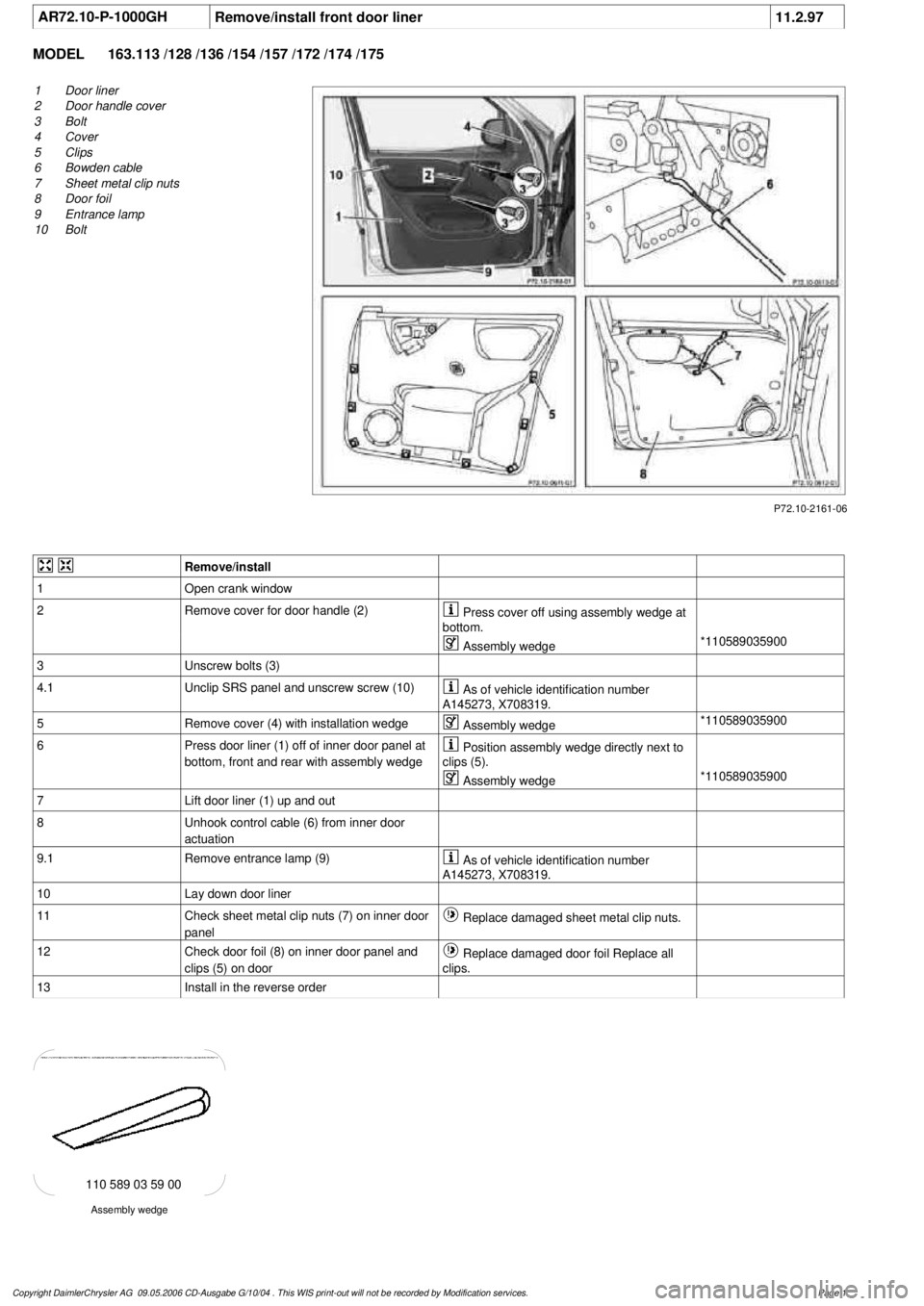
Remove/install front door liner
11.2.97
MODEL
163.113 /128 /136 /154 /157 /172 /174 /175
P72.10-2161-06
1
Door liner
2
Door handle cover
3
Bolt
4
Cover
5
Clips
6
Bowden cable
7
Sheet metal clip nuts
8
Door foil
9
Entrance lamp
10
Bolt
Remove/install
1
Open crank window
2
Remove cover for door handle (2)
Press cover off using assembly wedge at
bottom.
Assembly wedge
*110589035900
3
Unscrew bolts (3)
4.1
Unclip SRS panel and unscrew screw (10)
As of vehicle identification number
A145273, X708319.
5
Remove cover (4) with installation wedge
Assembly wedge
*110589035900
6
Press door liner (1) off of inner door panel at
bottom, front and rear with assembly wedge
Position assembly wedge directly next to
clips (5).
Assembly wedge
*110589035900
7
Lift door liner (1) up and out
8
Unhook control cable (6) from inner door
actuation
9.1
Remove entrance lamp (9)
As of vehicle identification number
A145273, X708319.
10
Lay down door liner
11
Check sheet metal clip nuts (7) on inner door
panel
Replace damaged sheet metal clip nuts.
12
Check door foil (8) on inner door panel and
clips (5) on door
Replace damaged door foil Replace all
clips.
13
Install in the reverse order
Assembly wedge
110 589 03 59 00
Copyright DaimlerChrysler AG 09.05.2006 CD-Ausgabe G/10/04 . This WIS print-out will not be recorde
d by Modification services.
Page 1
Page 2116 of 4133
AR72.10-P-4011GH
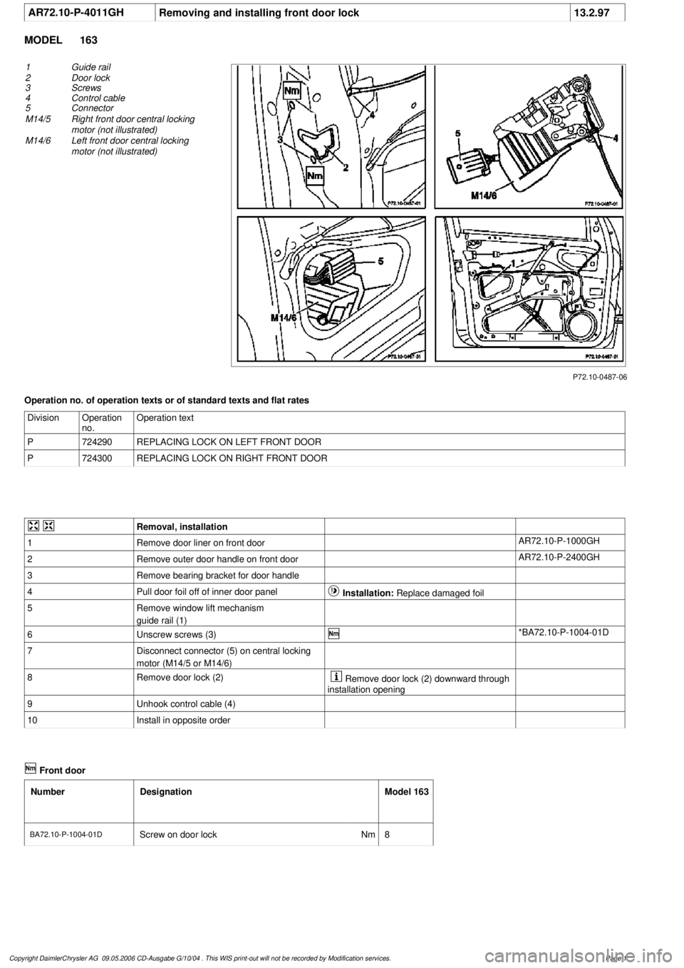
Removing and installing front door lock
13.2.97
MODEL
163
P72.10-0487-06
1
Guide rail
2
Door lock
3
Screws
4
Control cable
5
Connector
M14/5
Right front door central locking
motor (not illustrated)
M14/6
Left front door central locking
motor (not illustrated)
Operation no. of operation texts or of standard texts and flat rates
Division
Operation
no.
Operation text
P
724290
REPLACING LOCK ON LEFT FRONT DOOR
P
724300
REPLACING LOCK ON RIGHT FRONT DOOR
Removal, installation
1
Remove door liner on front door
AR72.10-P-1000GH
2
Remove outer door handle on front door
AR72.10-P-2400GH
3
Remove bearing bracket for door handle
4
Pull door foil off of inner door panel
Installation:
Replace damaged foil
5
Remove window lift mechanism
guide rail (1)
6
Unscrew screws (3)
*BA72.10-P-1004-01D
7
Disconnect connector (5) on central locking
motor (M14/5 or M14/6)
8
Remove door lock (2)
Remove door lock (2) downward through
installation opening
9
Unhook control cable (4)
10
Install in opposite order
Front door
Number
Designation
Model 163
BA72.10-P-1004-01D
Screw on door lock
Nm
8
Copyright DaimlerChrysler AG 09.05.2006 CD-Ausgabe G/10/04 . This WIS print-out will not be recorde
d by Modification services.
Page 1
Page 2124 of 4133
AR72.12-P-1010GH
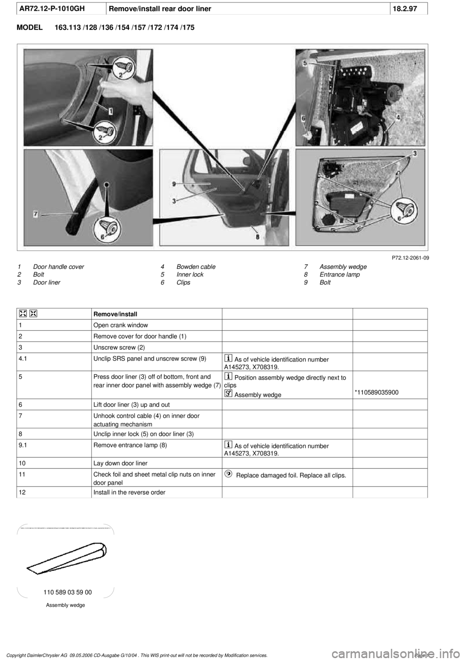
Remove/install rear door liner
18.2.97
MODEL
163.113 /128 /136 /154 /157 /172 /174 /175
P72.12-2061-09
1
Door handle cover
2
Bolt
3
Door liner
7
Assembly wedge
8
Entrance lamp
9
Bolt
4
Bowden cable
5
Inner lock
6
Clips
Remove/install
1
Open crank window
2
Remove cover for door handle (1)
3
Unscrew screw (2)
4.1
Unclip SRS panel and unscrew screw (9)
As of vehicle identification number
A145273, X708319.
5
Press door liner (3) off of bottom, front and
rear inner door panel with assembly wedge (7)
Position assembly wedge directly next to
clips
Assembly wedge
*110589035900
6
Lift door liner (3) up and out
7
Unhook control cable (4) on inner door
actuating mechanism
8
Unclip inner lock (5) on door liner (3)
9.1
Remove entrance lamp (8)
As of vehicle identification number
A145273, X708319.
10
Lay down door liner
11
Check foil and sheet metal clip nuts on inner
door panel
Replace damaged foil. Replace all clips.
12
Install in the reverse order
Assembly wedge
110 589 03 59 00
Copyright DaimlerChrysler AG 09.05.2006 CD-Ausgabe G/10/04 . This WIS print-out will not be recorde
d by Modification services.
Page 1
Page 2144 of 4133
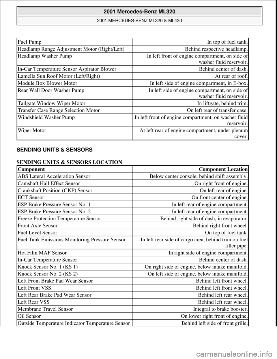
SENDING UNITS & SENSORS
SENDING UNITS & SENSORS LOCATION
Fuel PumpIn top of fuel tank.
Headlamp Range Adjustment Motor (Right/Left)Behind respective headlamp.
Headlamp Washer PumpIn left front of engine compartment, on side of
washer fluid reservoir.
In-Car Temperature Sensor Aspirator BlowerBehind center of dash.
Lamella Sun Roof Motor (Left/Right)At rear of roof.
Module Box Blower MotorIn left side of engine compartment, in E-box.
Rear Wall Door Washer PumpIn left side of engine compartment, on side of
washer fluid reservoir.
Tailgate Window Wiper MotorIn liftgate, behind trim.
Transfer Case Range Selection MotorOn left rear of transfer case.
Windshield Washer PumpIn left front of engine compartment, on washer fluid
reservoir.
Wiper MotorAt left rear of engine compartment, under plenum
cover.
ComponentComponent Location
ABS Lateral Acceleration SensorBelow center console, behind shift assembly.
Camshaft Hall Effect SensorOn right front of engine.
Crankshaft Position (CKP) SensorOn left rear of engine.
ECT SensorOn front center of engine.
ESP Brake Pressure Sensor No. 1In left rear of engine compartment.
ESP Brake Pressure Sensor No. 2In left rear of engine compartment.
Freeze Protection Temperature SensorBehind right side of dash, in evaporator.
Front Axle SensorBehind right front wheel.
Fuel Level SensorOn top of fuel tank.
Fuel Tank Emissions Monitoring Pressure SensorIn left rear side of cargo area, behind trim on fuel
filler pipe.
Hot Film MAF SensorIn right side of engine compartment.
In-Car Temperature SensorBehind center of dash.
Knock Sensor No. 1 (KS 1)On right side of engine, below intake manifold.
Knock Sensor No. 2 (KS 2)On left side of engine, below intake manifold.
Left Front Brake Pad Wear SensorBehind left front wheel.
Left Front VSSBehind left front wheel.
Left Rear Brake Pad Wear SensorBehind left rear wheel.
Left Rear VSSBehind left rear wheel.
Membrane Travel SensorIntegral to brake booster.
Oil SensorOn lower right front of engine.
Outside Temperature Indicator Temperature SensorBehind left side of front grille.
2001 Mercedes-Benz ML320
2001 MERCEDES-BENZ ML320 & ML430
me
Saturday, October 02, 2010 3:21:17 PMPage 4 © 2006 Mitchell Repair Information Company, LLC.
Page 2146 of 4133
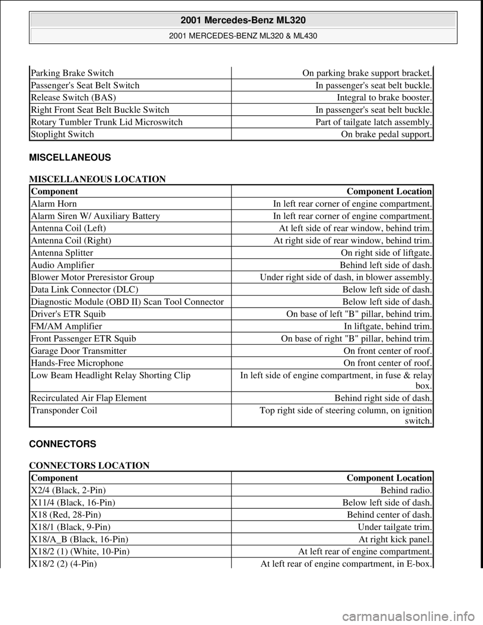
MISCELLANEOUS
MISCELLANEOUS LOCATION
CONNECTORS
CONNECTORS LOCATION
Parking Brake SwitchOn parking brake support bracket.
Passenger's Seat Belt SwitchIn passenger's seat belt buckle.
Release Switch (BAS)Integral to brake booster.
Right Front Seat Belt Buckle SwitchIn passenger's seat belt buckle.
Rotary Tumbler Trunk Lid MicroswitchPart of tailgate latch assembly.
Stoplight SwitchOn brake pedal support.
ComponentComponent Location
Alarm HornIn left rear corner of engine compartment.
Alarm Siren W/ Auxiliary BatteryIn left rear corner of engine compartment.
Antenna Coil (Left)At left side of rear window, behind trim.
Antenna Coil (Right)At right side of rear window, behind trim.
Antenna SplitterOn right side of liftgate.
Audio AmplifierBehind left side of dash.
Blower Motor Preresistor GroupUnder right side of dash, in blower assembly.
Data Link Connector (DLC)Below left side of dash.
Diagnostic Module (OBD II) Scan Tool ConnectorBelow left side of dash.
Driver's ETR SquibOn base of left "B" pillar, behind trim.
FM/AM AmplifierIn liftgate, behind trim.
Front Passenger ETR SquibOn base of right "B" pillar, behind trim.
Garage Door TransmitterOn front center of roof.
Hands-Free MicrophoneOn front center of roof.
Low Beam Headlight Relay Shorting ClipIn left side of engine compartment, in fuse & relay
box.
Recirculated Air Flap ElementBehind right side of dash.
Transponder CoilTop right side of steering column, on ignition
switch.
ComponentComponent Location
X2/4 (Black, 2-Pin)Behind radio.
X11/4 (Black, 16-Pin)Below left side of dash.
X18 (Red, 28-Pin)Behind center of dash.
X18/1 (Black, 9-Pin)Under tailgate trim.
X18/A_B (Black, 16-Pin)At right kick panel.
X18/2 (1) (White, 10-Pin)At left rear of engine compartment.
X18/2 (2) (4-Pin)At left rear of engine compartment, in E-box.
2001 Mercedes-Benz ML320
2001 MERCEDES-BENZ ML320 & ML430
me
Saturday, October 02, 2010 3:21:17 PMPage 6 © 2006 Mitchell Repair Information Company, LLC.
Page 2155 of 4133
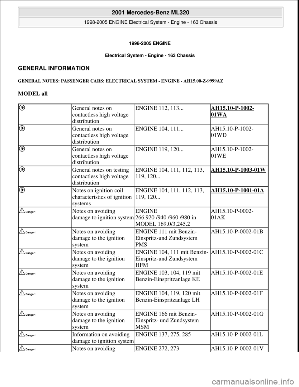
1998-2005 ENGINE
Electrical System - Engine - 163 Chassis
GENERAL INFORMATION
GENERAL NOTES: PASSENGER CARS: ELECTRICAL SYSTEM - ENGINE - AH15.00-Z-9999AZ
MODEL all
General notes on
contactless high voltage
distributionENGINE 112, 113...AH15.10-P-1002-
01WA
General notes on
contactless high voltage
distributionENGINE 104, 111...AH15.10-P-1002-
01WD
General notes on
contactless high voltage
distributionENGINE 119, 120...AH15.10-P-1002-
01WE
General notes on testing
contactless high voltage
distributionENGINE 104, 111, 112, 113,
119, 120...AH15.10-P-1003-01W
Notes on ignition coil
characteristics of ignition
systemsENGINE 104, 111, 112, 113,
119, 120...AH15.10-P-1001-01A
Notes on avoiding
damage to ignition systemENGINE
266.920 /940 /960 /980 in
MODEL 169.0/3,245.2AH15.10-P-0002-
01AK
Notes on avoiding
damage to the ignition
systemENGINE 111 mit Benzin-
Einspritz-und Zundsystem
PMSAH15.10-P-0002-01B
Notes on avoiding
damage to the ignition
systemENGINE 104, 111 mit Benzin-
Einspritz-und Zundsystem
HFMAH15.10-P-0002-01C
Notes on avoiding
damage to the ignition
systemENGINE 103, 104, 119 mit
Benzin-Einspritzanlage KEAH15.10-P-0002-01E
Notes on avoiding
damage to the ignition
systemENGINE 104, 119, 120 mit
Benzin-Einspritzanlage LHAH15.10-P-0002-01F
Notes on avoiding
damage to the ignition
systemENGINE 166 mit Benzin-
Einspritz- und Zundsystem
MSMAH15.10-P-0002-01G
Information on avoiding
damage to ignition systemENGINE 137, 275, 285AH15.10-P-0002-01L
Notes on avoiding ENGINE 272, 273AH15.10-P-0002-01V
2001 Mercedes-Benz ML320
1998-2005 ENGINE Electrical System - Engine - 163 Chassis
2001 Mercedes-Benz ML320
1998-2005 ENGINE Electrical System - Engine - 163 Chassis
me
Saturday, October 02, 2010 3:18:54 PMPage 1 © 2006 Mitchell Repair Information Company, LLC.
me
Saturday, October 02, 2010 3:18:57 PMPage 1 © 2006 Mitchell Repair Information Company, LLC.