1997 MERCEDES-BENZ ML500 oil
[x] Cancel search: oilPage 1450 of 4133
Transfer Case Control Module (N78):
Position of Transfer Case (off-road or on-road ratio)
Engine Torque
Engine Speed
Accelerator Pedal Position
Gear Soft
Engine Status
The following information is output to other systems:
ME-SFI Control Module (N3/10) or CDI Control Module (N3/9):
Kickdown Switch (S16/6)
Engage Drive Mode
Traction System Control Module (N47):
Transmission Ratio
Speeds
Oil Level Control, Function
Operation - The oil level control system seals the opening between the oil gallery and gearset chamber so that
the rotating gearsets do not splash about in oil as the oil level rises. The oil level control reduces power loss and
prevents oil from being thrown out of the transmission housing at high oil temperatures.
Float, Location/Function
See SHIFT PRESSURE REGULATING VALVE, LOCATION/TASK/FUNCTION
.
Transmission Housing Breathing, Location/Task
See TRANSMISSION HOUSING BREATHING, LOCATION/TASK
.
Function Of Torque Converter Lockup Clutch Control
Operation
2001 Mercedes-Benz ML320
1998-03 AUTOMATIC TRANSMISSIONS Complete Transmissions - ML 320 - 722.662
me
Saturday, October 02, 2010 3:15:29 PMPage 281 © 2006 Mitchell Repair Information Company, LLC.
Page 1454 of 4133
Courtesy of MERCEDES-BENZ OF NORTH AMERICA.
Operation
The driver's wish for maximum acceleration of the vehicle is met with the kick-down function. See Fig. 160.
When the kick-down switch (S16/6) is operated a CAN Signal is passed on from the electronic selector lever
module control module (N15/5) to the ETC control module (N15/3) via the electronic accelerator.
Based on this information the ETC control module (N15/3) actuates the solenoid valves so that the upshifts and
downshifts take place at higher engine speeds in order to achieve maximum performance.
Kick-Down Switch, Location/Task/Design
See KICK
-DOWN SWITCH, LOCATION/TASK/DESIGN.
Hydropneumatic Transmission Control, Function (Without Touch Shift)
Operation
The hydropneumatic transmission control is divided into electronic and hydraulic transmission control.
While the electronic transmission control is responsible for gear selection and for matching the pressures to the
torque to be transmitted, the transmission's power supply control occurs via hydraulic elements in the
electrohydraulic control module. The oil supply to the hydraulic elements, such as the hydrodynamic torque
converter, the shift elements and the hydraulic transmission control, is provided by way of an oil pump
connected with the torque converter.
The electronic transmission control (ETC) allows for the precise adaptation of pressures to the corresponding
operating conditions and to the engine output during the gearshift phase, resulting in a noticeable improvement
in shift quality.
It is possible to reach the engine RPM limit in the individual gears using full throttle and kick-down. The shift
range can be changed in the forward gears while driving, but the electronic transmission control (ETC) employs
a downshift safeguard to prevent over-revving the engine.
The system offers the additional advantage of flexible adaptation to different vehicle and engine variants.
ETC Control Module, Location/Task
See ETC CONTROL UNIT, LOCATION/TASK
.
Electric Control Module, Location/Task/Design/Function
See ELECTRONIC CONTROL MODULE, LOCATION/TASK/DESIGN/FUNCTION
.
Kickdown Switch, Location/Task/Design/Function Model 163 Without Touch Shift
2001 Mercedes-Benz ML320
1998-03 AUTOMATIC TRANSMISSIONS Complete Transmissions - ML 320 - 722.662
me
Saturday, October 02, 2010 3:15:29 PMPage 285 © 2006 Mitchell Repair Information Company, LLC.
Page 1455 of 4133
See KICKDOWN SWITCH, LOCATION/TASK/DESIGN/FUNCTION MODEL 163 WITHOUT
TOUCH SHIFT.
Starter Lock-Out Contact, Location/Task/Design/Function
See STARTER LOCK
-OUT CONTACT, LOCATION/TASK/DESIGN/FUNCTION.
Temperature Sensor, Location/Task/Design/Function
See TEMPERATURE SENSOR, LOCATION/TASK/DESIGN/FUNCTION
.
Wheel Speed Sensor, Location/Task/Function
See WHEEL SPEED SENSOR, LOCATION/TASK/FUNCTION
.
Location/Task/Design/Function Of Oil Pump
See LOCATION/TASK/DESIGN/FUNCTION OF OIL PUMP
.
Kickdown Switch, Location/Task/Design/Function Model 163 Without Touch Shift
2001 Mercedes-Benz ML320
1998-03 AUTOMATIC TRANSMISSIONS Complete Transmissions - ML 320 - 722.662
me
Saturday, October 02, 2010 3:15:29 PMPage 286 © 2006 Mitchell Repair Information Company, LLC.
Page 1467 of 4133
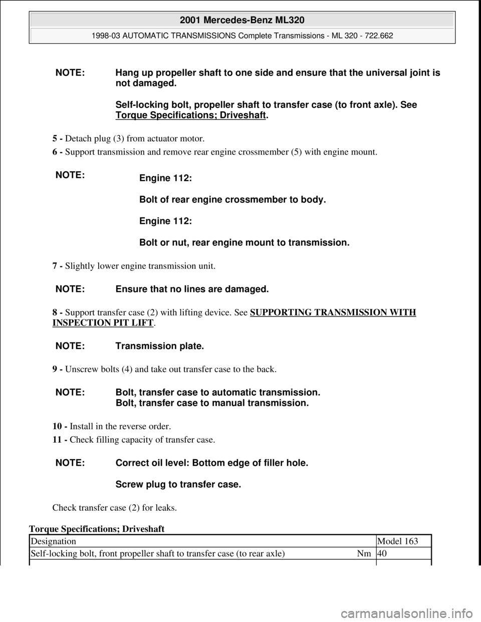
5 - Detach plug (3) from actuator motor.
6 - Support transmission and remove rear engine crossmember (5) with engine mount.
7 - Slightly lower engine transmission unit.
8 - Support transfer case (2) with lifting device. See SUPPORTING TRANSMISSION WITH
INSPECTION PIT LIFT.
9 - Unscrew bolts (4) and take out transfer case to the back.
10 - Install in the reverse order.
11 - Check filling capacity of transfer case.
Check transfer case (2) for leaks.
Torque Specifications; Driveshaft NOTE: Hang up propeller shaft to one side and ensure that the universal joint is
not damaged.
Self-locking bolt, propeller shaft to transfer case (to front axle). See
Torque Specifications; Driveshaft
.
NOTE:
Engine 112:
Bolt of rear engine crossmember to body.
Engine 112:
Bolt or nut, rear engine mount to transmission.
NOTE: Ensure that no lines are damaged.
NOTE: Transmission plate.
NOTE: Bolt, transfer case to automatic transmission.
Bolt, transfer case to manual transmission.
NOTE: Correct oil level: Bottom edge of filler hole.
Screw plug to transfer case.
DesignationModel 163
Self-locking bolt, front propeller shaft to transfer case (to rear axle)Nm40
2001 Mercedes-Benz ML320
1998-03 AUTOMATIC TRANSMISSIONS Complete Transmissions - ML 320 - 722.662
me
Saturday, October 02, 2010 3:15:30 PMPage 298 © 2006 Mitchell Repair Information Company, LLC.
Page 1471 of 4133
Basically automatic transmission 722.6 with electronic control offers the following advantages:
Reduced Fuel Consumption
Improved Shift Comfort
More Favorable Gear Steps As A Result Of 5 Gears
Enhanced Life And Reliability
Reduced Servicing Costs
The electrohydraulic control unit is bolted onto the bottom of the transmission housing. The end of the
transmission is formed by an oil pan made of sheet steel.
The oil pressure for the converter lockup clutch and center multiple-disc clutch is supplied via holes in the input
shaft. The oil pressure to the rear multiple-disc clutch is routed through the output shaft. The lubricating oil is
supplied and distributed by additional bore holes in both shafts. All bearing points of the gear sets as well as
freewheels and shift elements are supplied with lubricating oil.
The parking lock gear and drive flange are connected to the output shaft by gearing.
Freewheels F1 and F2 optimize shifting. The front freewheel (F1) rests against the stator shaft extension on the
transmission side and connects the sun gear of the front planetary gear set to the transmission housing in the
locking direction.
The torque converter housing and transmission housing are made of a metal alloy. They are bolted together and
centered via the outer multiple-disc carrier of the multiple-disc brake B1. A coated intermediate panel seals the
two components.
The oil pump and outer multiple-disc carrier of the front multiple-disc brake are bolted to the converter housing.
The mechanical part consists of the propeller shaft, output shaft, a sun gear shaft and three planetary gearsets
which are coupled together.
In transmissions for powerful engines, the planetary gearsets have 4 planetary gears, while for less powerful
engines the front and rear planetary gear system has three planetary gear wheels. The stator shaft is pressed into
this and is secured against turning by a spline.
The rear freewheel F2 connects the sun gear of the center planetary gear set to the sun gear of the rear planetary
gearset in the locking direction.
The electrohydraulic control unit consists of the shift plate made of light alloy for hydraulic control and an
electronic control unit.
The electrical control unit consists of a supporting body made of plastic in which the electrical components are
combined. The shell is screwed to the shift plate. Conductor tracks which are integrated into the shell, connect
the electric components to a plug connector. This 13-pin plug connector forms the connection with the vehicle-
side wiring harness and with the ETC 5 (electronic transmission control) control module (N15/5) via a bayonet
lock.
2001 Mercedes-Benz ML320
1998-03 AUTOMATIC TRANSMISSIONS Complete Transmissions - ML 320 - 722.662
me
Saturday, October 02, 2010 3:15:30 PMPage 302 © 2006 Mitchell Repair Information Company, LLC.
Page 1472 of 4133
SURVEY OF SYSTEM COMPONENTS, AUTOMATIC TRANSMISSION (AT), LOCATION, TASK, DESIGN
Function Of Gear Change
See FUNCTION OF GEAR CHANGE
.
Shifting N to D (1st Gear), Function
See SHIFTING N TO D (1ST GEAR), FUNCTION
.
Shift From 1 to 2, Function
See SHIFT FROM 1 TO 2, FUNCTION
.
Limp-Home Mode, function
See LIMP
-HOME MODE, FUNCTION.
Operating Pressure, Function
See OPERATING PRESSURE, FUNCTION
.
Lubricating Pressure, Function
See LUBRICATING PRESSURE, FUNCTION
.
Shift Pressure, Function
See SHIFT PRESSURE, FUNCTION
.
Modulating Pressure, Function
See MODULATING PRESSURE, FUNCTION
.
Regulating Valve Pressure, Function
See REGULATING VALVE PRESSURE, FUNCTION
.
Shift Valve Pressure, Function
See SHIFT VALVE PRESSURE, FUNCTION
.
Manual Drive Mode Selection, Function
See MANUAL DRIVE MODE SELECTION, FUNCTION
.
Oil Level Control, Function
2001 Mercedes-Benz ML320
1998-03 AUTOMATIC TRANSMISSIONS Complete Transmissions - ML 320 - 722.662
me
Saturday, October 02, 2010 3:15:30 PMPage 303 © 2006 Mitchell Repair Information Company, LLC.
Page 1473 of 4133
See OIL LEVEL CONTROL, FUNCTION
.
Function of Torque Converter Lockup Clutch Control
See FUNCTION OF TORQUE CONVERTER LOCKUP CLUTCH CONTROL
.
Torque Converter Lockup Clutch Control Pressure, Function
See TORQUE CONVERTER LOCKUP CLUTCH CONTROL PRESSURE, FUNCTION
.
Function Of Locking Of Selector Lever Position "P"
See FUNCTION OF LOCKING OF SELECTOR LEVER POSITION "P"
.
Ignition Lock Locking, Function
See IGNITION LOCK INTERLOCK
.
Function Of Shift Lock Override
See FUNCTION OF SHIFT LOCK OVERRIDE
.
Survey Of System Components, Automatic Transmission, Location/Task/Design/Function
See SURVEY OF SYSTEM COMPONENTS, AUTOMATIC TRANSMISSION,
LOCATION/TASK/DESIGN/FUNCTION.
2001 Mercedes-Benz ML320
1998-03 AUTOMATIC TRANSMISSIONS Complete Transmissions - ML 320 - 722.662
me
Saturday, October 02, 2010 3:15:30 PMPage 304 © 2006 Mitchell Repair Information Company, LLC.
Page 1547 of 4133
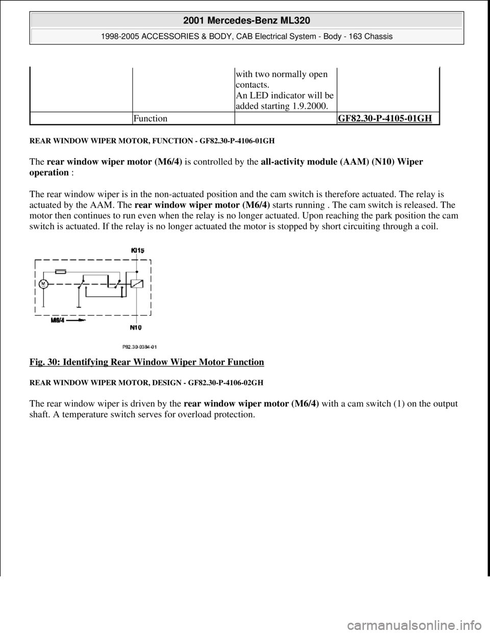
REAR WINDOW WIPER MOTOR, FUNCTION - GF82.30-P-4106-01GH
The rear window wiper motor (M6/4) is controlled by the all-activity module (AAM) (N10) Wiper
operation :
The rear window wiper is in the non-actuated position and the cam switch is therefore actuated. The relay is
actuated by the AAM. The rear window wiper motor (M6/4) starts running . The cam switch is released. The
motor then continues to run even when the relay is no longer actuated. Upon reaching the park position the cam
switch is actuated. If the relay is no longer actuated the motor is stopped by short circuiting through a coil.
Fig. 30: Identifying Rear Window Wiper Motor Function
REAR WINDOW WIPER MOTOR, DESIGN - GF82.30-P-4106-02GH
The rear window wiper is driven by the rear window wiper motor (M6/4) with a cam switch (1) on the output
shaft. A temperature switch serves for overload protection.
with two normally open
contacts.
An LED indicator will be
added starting 1.9.2000.
Function GF82.30-P-4105-01GH
2001 Mercedes-Benz ML320
1998-2005 ACCESSORIES & BODY, CAB Electrical System - Body - 163 Chassis
me
Saturday, October 02, 2010 3:30:05 PMPage 52 © 2006 Mitchell Repair Information Company, LLC.