Page 1225 of 4133
See MULTIPLE
-DISC BRAKE, LOCATION/TASK/DESIGN/FUNCTION.
Multi-Plate Clutch, Location/Task/Design/Function
See MULTI
-PLATE CLUTCH, LOCATION/TASK/DESIGN/FUNCTION.
Upshift/Downshift Solenoid Valve, Location/Task/Design/Function
See UPSHIFT/DOWNSHIFT SOLENOID VALVE, LOCATION/TASK/DESIGN/FUNCTION
.
Floor Shift, Location/Task/Design/Function
See FLOOR SHIFT, LOCATION/TASK/DESIGN/FUNCTION
.
Location/Task/Design/Function Of Oil Pump
See LOCATION/TASK/DESIGN/FUNCTION OF OIL PUMP
.
Parking Lock, Location/Task/Design/Function
See PARK PAWL, LOCATION/TASK/DESIGN/FUNCTION
.
Planetary Gear Set, Location/Task/Design/Function
See PLANETARY GEAR SET, LOCATION/TASK/DESIGN/FUNCTION
.
Position Indicator, Location/Task/Design/Function
See POSITION DISPLAY, LOCATION TASK
.
Location/Task/Design/Function Of PWM Solenoid Valve, Torque converter Lockup Clutch
See LOCATION/TASK/DESIGN/FUNCTION OF PWM SOLENOID VALVE, TORQUE
CONVERTER LOCKUP CLUTCH.
Modulating Pressure Regulating Solenoid Valve, Location/Task/Design/Function
See MODULATING PRESSURE REGULATING SOLENOID VALVE,
LOCATION/TASK/DESIGN/FUNCTION.
Shift Pressure Regulating Solenoid Valve, Location/Task/Design/Function
See SHIFT PRESSURE REGULATING SOLENOID VALVE,
LOCATION/TASK/DESIGN/FUNCTION.
Working Pressure Regulating Valve, Location/Task/Design/Function
2001 Mercedes-Benz ML320
1998-03 AUTOMATIC TRANSMISSIONS Complete Transmissions - ML 320 - 722.662
me
Saturday, October 02, 2010 3:15:26 PMPage 56 © 2006 Mitchell Repair Information Company, LLC.
Page 1232 of 4133
vehicle is stationary and the engine is idling, boosts the engine torque and provides infinitely variable
engine speed and torque matching when moving off.
Torque Converter, Design
The impeller (P) is connected to the engine, the turbine wheel (T) is connected to the transmission input
shaft.
The stator (L) is connected to the transmission housing via a freewheel and the stator shaft (8).
Torque Converter, Function
See TORQUE CONVERTER, FUNCTION
.
Torque Converter, Function
Due to the effect of centrifugal force, the blades of the impeller (P) pump the oil outwards to the turbine wheel
(T), causing it to rotate. See Fig. 31
. The turbine wheel blades direct the oil onto the blades of the stator, which
in turn push the oil back to the impeller (P) (arrow). This diversion at the stator (L), which is supported against
the transmission housing via the freewheel, produces and increase in torque. At the maximum speed difference
between the impeller and the turbine wheel (T), the torque conversion achieves its maximum value at a factor of
1.8 to 2.0, dropping to a torque ratio of 1:1 as the speeds converge. From this operating state onwards, also
referred to as the coupling point, the stator (l) rotates with the impeller (P) and the turbine wheel (T).
Efficiencies of up to approximately 98% are achieved in the coupling range.
The oil in the torque converter is constantly being replaced so that the heat produced in the operating phase can
be dissipated via the transmission oil cooler.
2001 Mercedes-Benz ML320
1998-03 AUTOMATIC TRANSMISSIONS Complete Transmissions - ML 320 - 722.662
me
Saturday, October 02, 2010 3:15:26 PMPage 63 © 2006 Mitchell Repair Information Company, LLC.
Page 1240 of 4133
Fig. 35: Electronic Control Module, Design
Courtesy of MERCEDES-BENZ OF NORTH AMERICA.
Structure
The electrical control unit (Y3/6) consists of a supporting body made from plastic, in which the electrical
components, RPM sensors 2 and 3 (Y3/6n2, Y3/6n3), the regulating solenoid valves (Y3/6y1, Y3/6y2), the shift
solenoid valves (Y3/6y6), the starter lockout contact (Y3/6s1) and transmission oil temperature sensor (Y3/6b1)
are combined. See Fig. 35
. Conductor tracks integrated into the shell connect the electric components to a plug
connection (11).
2001 Mercedes-Benz ML320
1998-03 AUTOMATIC TRANSMISSIONS Complete Transmissions - ML 320 - 722.662
me
Saturday, October 02, 2010 3:15:26 PMPage 71 © 2006 Mitchell Repair Information Company, LLC.
Page 1243 of 4133
Fig. 36: Electronic Control Module, Function
Courtesy of MERCEDES-BENZ OF NORTH AMERICA.
Operation
Signals from the ETC control module (N15/3) are conve rted into hydraulic functions in the electric valve
control unit (Y3/6). The RPM sensors (Y3/6n2, Y3/6n3) , the starter lockout contact (Y3/6s1) and the
transmission oil temperature sensor (Y3/6b1) of the electrical cont rol unit (Y3/6) supply the ETC control
module (N15/3) with input signals. The solenoid valves are controlled by the ETC control module (N15/3) and
trigger the hydraulic functions. See Fig. 36
.
Location/Task/Design/Function Of Freewheel
Fig. 37: Function Of Freewheel
Courtesy of MERCEDES-BENZ OF NORTH AMERICA.
Freewheel Location
2001 Mercedes-Benz ML320
1998-03 AUTOMATIC TRANSMI SSIONS Complete Transmissions - ML 320 - 722.662
me
Saturday, October 02, 2010 3:15:26 PMPage 74 © 2006 Mitchell Repair Information Company, LLC.
Page 1247 of 4133
Transmission Housing Breather, Location
The inside of the transmission and the breather (72) are connected by a channel which is cast into the
torque converter casing. See Fig. 39
.
Transmission Housing Breather, Task
The transmission housing vent compensated the pressure in the transmission housing if temperature-
related volume changes in the transmission oil and air occur.
Kick-Down Switch, Location/Task/Design
Fig. 40: Kickdown Switch, Location/Task/Design
Courtesy of MERCEDES-BENZ OF NORTH AMERICA.
Kick-Down Switch, Position
2001 Mercedes-Benz ML320
1998-03 AUTOMATIC TRANSMISSIONS Complete Transmissions - ML 320 - 722.662
me
Saturday, October 02, 2010 3:15:26 PMPage 78 © 2006 Mitchell Repair Information Company, LLC.
Page 1254 of 4133
Operation
If the piston (B1a) on multiple-disc brake B1 is subjected to oil pressure, it presses the internal and external
discs of the disc set together. See Fig. 44
. The front sun gear (v1) on the housing is locked via the internal
multiple-disc carrier (B1c). the front planetary gears (V2) roll on the front sun gear (V1).
If the rear multiple-disc brake (B2) is engaged via the piston (B2a), then this presses the disc set together. The
center sun gear (M1) is locked against the housing via the internal multiple-disc carrier (B2c). The center
planetary gears (m2) roll on the center sun gear (M1).
If the center multiple disc brake (B3) is engaged via the piston (B3a), then the rear planetary gear carrier (H3)
and the center hollow gear (M4) are locked. When the center multiple-disc brake (B3) is engaged the direction
of rotation reverses.
Multi-Plate Clutch, Location/Task/Design/Function
2001 Mercedes-Benz ML320
1998-03 AUTOMATIC TRANSMISSIONS Complete Transmissions - ML 320 - 722.662
me
Saturday, October 02, 2010 3:15:26 PMPage 85 © 2006 Mitchell Repair Information Company, LLC.
Page 1258 of 4133
Fig. 46: Multi-Disc Clutch, Function
Courtesy of MERCEDES-BENZ OF NORTH AMERICA.
Operation
Front Multiple-Disc Clutch (K1) - If the piston (K1a) on the front multiple-disc clutch (k1) is subjected to oil
pressure, it presses the internal and external discs of the disc set together. See Fig. 46.
The front sun gear (V1) is connected to the front planetary gear carrier (V3) via the external multiple-disc
carrier (K1b) and the internal multiple-disc carrier (k1b) and the internal multiple-disc carrier (K1c). The front
planetary gear set is thus locked and turns as a closed unit.
Center Multiple-Disc Clutch (K2) - If the center multiple-disc clutch (K2) is engaged via the piston (K2a), the
piston compresses the disc set Via the internal multiple-disc carrier (K2b) and the center planetary gear carrier
(M3) on which the internal discs are seated, the front hollow gear (v4) of the front planetary gear set is
connected to the center hollow gear (M4) of the center planetary gear set. The front hollow gear (V4) and the
center hollow gear (M4) move at the same speed as the drive shaft (1).
Rear Multiple-Disc Clutch (K3) - If the rear multiple-disc clutch (K3) is engaged via the piston (K3a), then
this compresses the disc set. The center sun gear (M1) of the center planetary gear set is connected to the rear
sun gear (H1) of the rear planetary gear carrier via the external multiple-disc carrier (K3b) and internal multiple-
disc carrier (K3c). The center sun gear (M1) and the rear sun gear (H1) move at the same speed.
Upshift/Downshift Solenoid Valve, Location/Task/Design/Function
2001 Mercedes-Benz ML320
1998-03 AUTOMATIC TRANSMISSIONS Complete Transmissions - ML 320 - 722.662
me
Saturday, October 02, 2010 3:15:26 PMPage 89 © 2006 Mitchell Repair Information Company, LLC.
Page 1263 of 4133
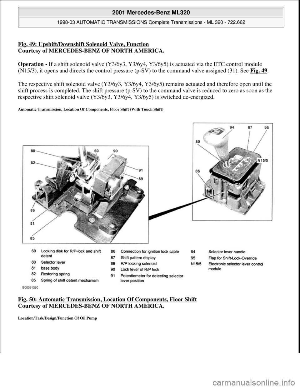
Fig. 49: Upshift/Downshift Solenoid Valve, Function
Courtesy of MERCEDES-BENZ OF NORTH AMERICA.
Operation - If a shift solenoid valve (Y3/6y3, Y3/6y4, Y3/6y5) is actuated via the ETC control module
(N15/3), it opens and directs the control pressure (p-SV) to the command valve assigned (31). See Fig. 49
.
The respective shift solenoid valve (Y3/6y3, Y3/6y4, Y3/6y5) remains actuated and therefore open until the
shift process is completed. The shift pressure (p-SV) to the command valve is reduced to zero as soon as the
respective shift solenoid valve (Y3/6y3, Y3/6y4, Y3/6y5) is switched de-energized.
Automatic Transmission, Location Of Components, Floor Shift (With Touch Shift)
Fig. 50: Automatic Transmission, Location Of Components, Floor Shift
Courtesy of MERCEDES-BENZ OF NORTH AMERICA.
Location/Task/Design/Function Of Oil Pump
2001 Mercedes-Benz ML320
1998-03 AUTOMATIC TRANSMISSIONS Complete Transmissions - ML 320 - 722.662
me
Saturday, October 02, 2010 3:15:26 PMPage 94 © 2006 Mitchell Repair Information Company, LLC.