Page 1143 of 4133

339 Index
Traction 308, 315
Trailer
Attaching 208
Loading 208
Towing 209
Trailer hitches 207
Trailer towing 206
Attaching a trailer 208
Checking weights 208
Electrical connections 207
Hitches 207
Loading 208
Weights and ratings 207
Trailer weights and ratings 207
Transfer case 315
Transmission control – LOW RANGE
mode 125
Switching off 125
Switching on 125
Transmission selector lever 264
Unlocking manually 264
Tread depth (tires) 230
Treadwear 308Trip computer* 29, 186
Average fuel consumption 189
Compass 187
Country 190
Distance remaining 189
Language 190
Selecting functions 186
Setting date 186
Stop watch 189
Switching on 186
Trip odometer
Resetting 118
Trip odometer display 117
Trunk see Cargo compartment 89
Turn signal lamps
Replacing bulbs 266, 267, 269
Turn signals 49
Additional in mirrors 266
Cleaning lenses 236
Front bulbs 266
Indicator lamps 25
Rear bulbs 267, 270
Turning off
Engine 54U
Unlocking 32, 88
Centrally from inside 94
Driver’s door in an emergency 261
Driver’s door, fuel filler flap 89
Fuel filler flap 214
In an emergency 261
Transmission selector lever
manually 264
Vehicle in an emergency 179
With the remote control 32
Upgrade signals
Tele Aid* 178
Uphill driving
Cruise control 151
Upholstery
Cleaning 239
Upshifting 120
Page 1144 of 4133

340 IndexUseful features 164
Ashtrays and cigarette lighter 168
Cup holder 166
Electrical outlet 170
Garage door opener 180
Interior storage spaces 164
Programming or reprogramming the in-
tegrated remote control 182
Tele Aid* 171
Telephone* 170
Trip computer* 186
V
Vehicle
Locking 28
Locking in an emergency 262
Lowering 276
Proper use of 17
Service battery 278
Towing 283
Unlocking 28
Unlocking in an emergency 261
Vehicle and trailer weights and
ratings 207
Vehicle battery 278Vehicle care
Cup holder 238
Engine cleaning 236
Gear selector lever 238
Hard plastic trim items 238
Headlamps 236
Instrument cluster 238
Leather upholstery 239
Light alloy wheels 238
MB Tex upholstery 239
Ornamental moldings 236
Paintwork 235
Parktronic* system sensor 237
Plastic and rubber parts 239
Power washer 235
Seat belts 238
Steering wheel 238
Tail lamps 236
Tar stains 235
Turn signals 236
Upholstery 239
Vehicle washing 236
Window cleaning 237
Wiper blades 237Vehicle identification number (VIN) 292
Vehicle jack 258
Vehicle lighting
Checking 216
Vehicle tool kit 257
Vehicle with CD-changer* 258
Vehicle washing 236
VIN (Vehicle Identification Number) 292,
315
Voice control system* 315
W
Warning indicators
Parktronic* 155
Warning sounds
Drivers seat belts 64
Parking brake 48
Warranty coverage 291
Washer fluid see Windshield washer fluid
Washing the vehicle 234
Page 1630 of 4133

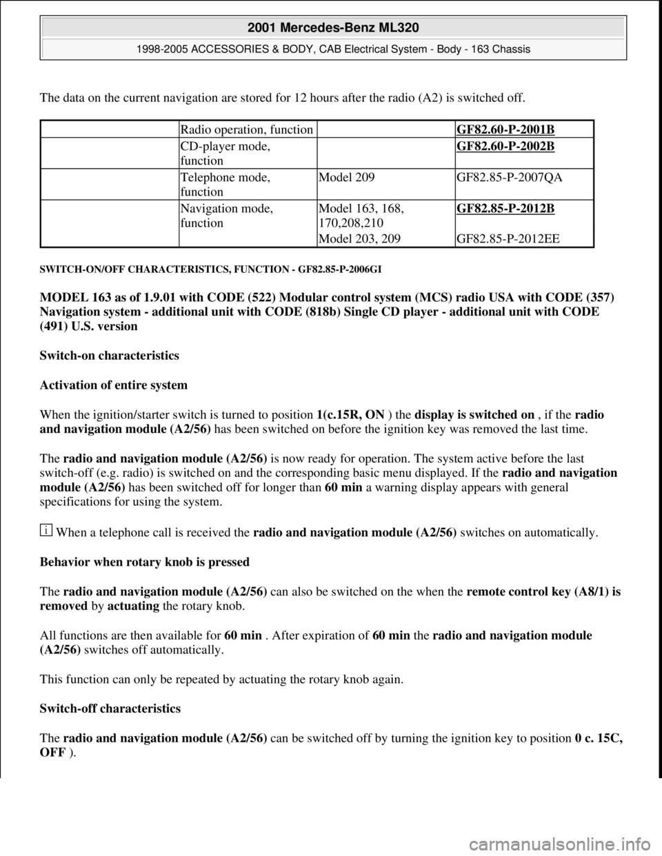
The data on the current navigation are stored for 12 hours after the radio (A2) is switched off.
SWITCH-ON/OFF CHARACTERISTICS, FUNCTION - GF82.85-P-2006GI
MODEL 163 as of 1.9.01 with CODE (522) Modular control system (MCS) radio USA with CODE (357)
Navigation system - additional unit with CODE (818b) Single CD player - additional unit with CODE
(491) U.S. version
Switch-on characteristics
Activation of entire system
When the ignition/starter switch is turned to position 1(c.15R, ON ) the display is switched on , if the radio
and navigation module (A2/56) has been switched on before the ignition key was removed the last time.
The radio and navigation module (A2/56) is now ready for operation. The system active before the last
switch-off (e.g. radio) is switched on and the corresponding basic menu displayed. If the radio and navigation
module (A2/56) has been switched off for longer than 60 min a warning display appears with general
specifications for using the system.
When a telephone call is received the radio and navigation module (A2/56) switches on automatically.
Behavior when rotary knob is pressed
The radio and navigation module (A2/56) can also be switched on the when the remote control ke
y (A8/1) is
removed by actuating the rotary knob.
All functions are then available for 60 min . After expiration of 60 min the radio and navigation module
(A2/56) switches off automatically.
This function can only be repeated by actuating the rotary knob again.
Switch-off characteristics
The radio and navigation module (A2/56) can be switched off by turning the ignition key to position 0 c. 15C,
OFF ).
Radio operation, function GF82.60-P-2001B
CD-player mode,
function GF82.60-P-2002B
Telephone mode,
functionModel 209GF82.85-P-2007QA
Navigation mode,
functionModel 163, 168,
170,208,210GF82.85-P-2012B
Model 203, 209GF82.85-P-2012EE
2001 Mercedes-Benz ML320
1998-2005 ACCESSORIES & BODY, CAB Electrical System - Body - 163 Chassis
me
Saturday, October 02, 2010 3:30:06 PMPage 135 © 2006 Mitchell Repair Information Company, LLC.
Page 1666 of 4133

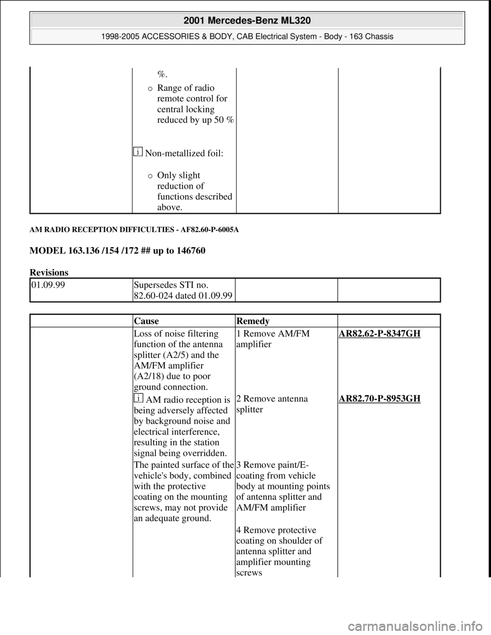
AM RADIO RECEPTION DIFFICULTIES - AF82.60-P-6005A
MODEL 163.136 /154 /172 ## up to 146760
Revisions
%.
Range of radio
remote control for
central locking
reduced by up 50 %
Non-metallized foil:
Only slight
reduction of
functions described
above.
01.09.99Supersedes STI no.
82.60-024 dated 01.09.99
CauseRemedy
Loss of noise filtering
function of the antenna
splitter (A2/5) and the
AM/FM amplifier
(A2/18) due to poor
ground connection.1 Remove AM/FM
amplifierAR82.62-P-8347GH
AM radio reception is
being adversely affected
by background noise and
electrical interference,
resulting in the station
signal being overridden.2 Remove antenna
splitterAR82.70-P-8953GH
The painted surface of the
vehicle's body, combined
with the protective
coating on the mounting
screws, may not provide
an adequate ground.3 Remove paint/E-
coating from vehicle
body at mounting points
of antenna splitter and
AM/FM amplifier
4 Remove protective
coating on shoulder of
antenna splitter and
amplifier mounting
screws
2001 Mercedes-Benz ML320
1998-2005 ACCESSORIES & BODY, CAB Electrical System - Body - 163 Chassis
me
Saturday, October 02, 2010 3:30:07 PMPage 171 © 2006 Mitchell Repair Information Company, LLC.
Page 1851 of 4133
Fig. 266: Identifying Guide Hole, Guide Lugs And Monitor Wiring Harness
16. Provide four further bore holes with Ø = 5 mm through bracket and crossmember of tilting/sliding roof
frame.
Use guide holes (18) provided in the bracket. To prevent damage to the vehicle roof, limit drilling
depth to 10 mm. Cover interior to collect the chips.
17. Rivet bracket with rivets supplied to crossmember of tilting/ sliding roof frame.
4 rivets.
18. Install edge guard for sliding/pop-up roof cutout in headliner.
19. Insert monitor wiring harness into video monitor unit (19).
20. Open video display (20) and remote control storage compartment (21).
2001 Mercedes-Benz ML320
1998-2005 ACCESSORIES & BODY, CAB Electrical System - Body - 163 Chassis
me
Saturday, October 02, 2010 3:30:11 PMPage 356 © 2006 Mitchell Repair Information Company, LLC.
Page 1852 of 4133

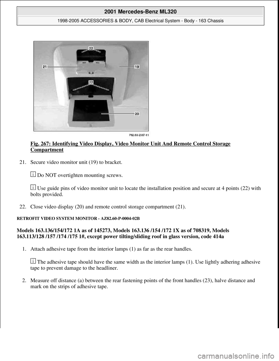
Fig. 267: Identifying Video Display, Video Monitor Unit And Remote Control Storage
Compartment
21. Secure video monitor unit (19) to bracket.
Do NOT overtighten mounting screws.
Use guide pins of video monitor unit to locate the installation position and secure at 4 points (22) with
bolts provided.
22. Close video display (20) and remote control storage compartment (21).
RETROFIT VIDEO SYSTEM MONITOR - AZ82.60-P-0004-02B
Models 163.136/154/172 1A as of 145273, Models 163.136 /154 /172 1X as of 708319, Models
163.113/128 /157 /174 /175 1#, except power tilting/sliding roof in glass version, code 414a
1. Attach adhesive tape from the interior lamps (1) as far as the rear handles.
The adhesive tape should have the same width as the interior lamps (1). Use lightly adhering adhesive
tape to prevent damage to the headliner.
2. Measure off distance (a) between the rear fastening points of the front handles (23), halve distance and
mark on the strips of adhesive tape.
2001 Mercedes-Benz ML320
1998-2005 ACCESSORIES & BODY, CAB Electrical System - Body - 163 Chassis
me
Saturday, October 02, 2010 3:30:11 PMPage 357 © 2006 Mitchell Repair Information Company, LLC.
Page 1857 of 4133

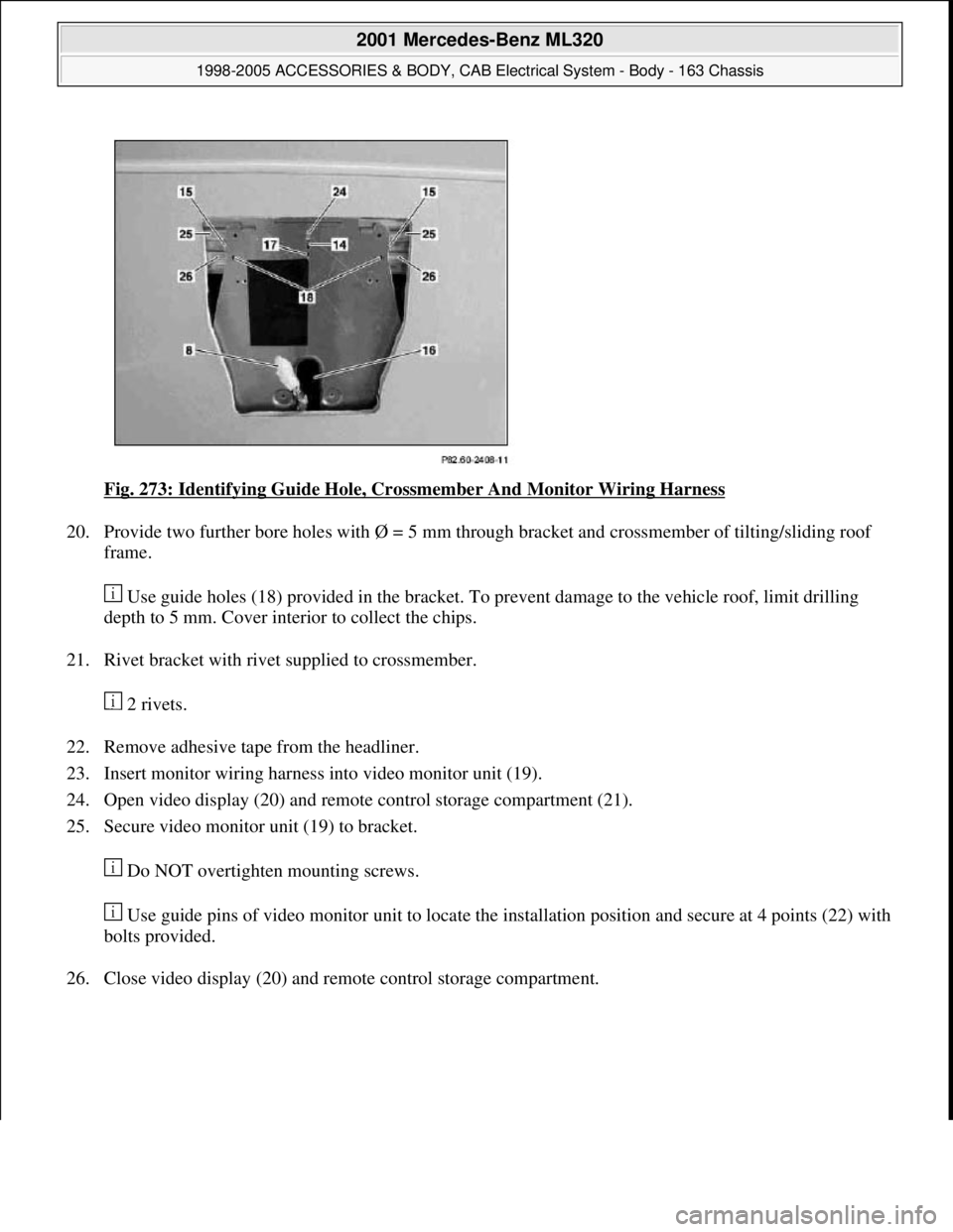
Fig. 273: Identifying Guide Hole, Crossmember And Monitor Wiring Harness
20. Provide two further bore holes with Ø = 5 mm through bracket and crossmember of tilting/sliding roof
frame.
Use guide holes (18) provided in the bracket. To prevent damage to the vehicle roof, limit drilling
depth to 5 mm. Cover interior to collect the chips.
21. Rivet bracket with rivet supplied to crossmember.
2 rivets.
22. Remove adhesive tape from the headliner.
23. Insert monitor wiring harness into video monitor unit (19).
24. Open video display (20) and remote control storage compartment (21).
25. Secure video monitor unit (19) to bracket.
Do NOT overtighten mounting screws.
Use guide pins of video monitor unit to locate the installation position and secure at 4 points (22) with
bolts provided.
26. Close video display (20) and remote control storage compartment.
2001 Mercedes-Benz ML320
1998-2005 ACCESSORIES & BODY, CAB Electrical System - Body - 163 Chassis
me
Saturday, October 02, 2010 3:30:11 PMPage 362 © 2006 Mitchell Repair Information Company, LLC.
Page 1858 of 4133
Fig. 274: Identifying Video Display, Video Monitor Unit And Remote Control Storage
Compartment
RETROFIT VIDEO SYSTEM MONITOR - AZ82.60-P-0004-02C
Model 163.136 /154 /172 2A as of 145273, Models 163.136 /154 /172 2X as of 708319, Models
163.113/128 /157 /174 /175 2#, with power tilting/sliding roof in glass version, Code 414a
1. Measure from the corner (1) of the tilting/ sliding roof frame (2) the dimension (a=410 mm) to the middle
of the tilting/ sliding roof frame and mark the frame.
Do NOT mark the headliner. By cross-measuring from the other corner check whether the mark is in
the center.
2001 Mercedes-Benz ML320
1998-2005 ACCESSORIES & BODY, CAB Electrical System - Body - 163 Chassis
me
Saturday, October 02, 2010 3:30:11 PMPage 363 © 2006 Mitchell Repair Information Company, LLC.