1997 MERCEDES-BENZ ML500 remote control
[x] Cancel search: remote controlPage 1863 of 4133
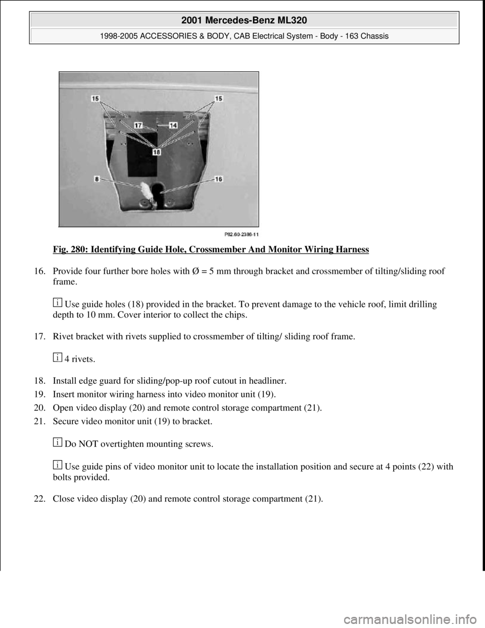
Fig. 280: Identifying Guide Hole, Crossmember And Monitor Wiring Harness
16. Provide four further bore holes with Ø = 5 mm through bracket and crossmember of tilting/sliding roof
frame.
Use guide holes (18) provided in the bracket. To prevent damage to the vehicle roof, limit drilling
depth to 10 mm. Cover interior to collect the chips.
17. Rivet bracket with rivets supplied to crossmember of tilting/ sliding roof frame.
4 rivets.
18. Install edge guard for sliding/pop-up roof cutout in headliner.
19. Insert monitor wiring harness into video monitor unit (19).
20. Open video display (20) and remote control storage compartment (21).
21. Secure video monitor unit (19) to bracket.
Do NOT overtighten mounting screws.
Use guide pins of video monitor unit to locate the installation position and secure at 4 points (22) with
bolts provided.
22. Close video display (20) and remote control storage compartment (21).
2001 Mercedes-Benz ML320
1998-2005 ACCESSORIES & BODY, CAB Electrical System - Body - 163 Chassis
me
Saturday, October 02, 2010 3:30:11 PMPage 368 © 2006 Mitchell Repair Information Company, LLC.
Page 1864 of 4133
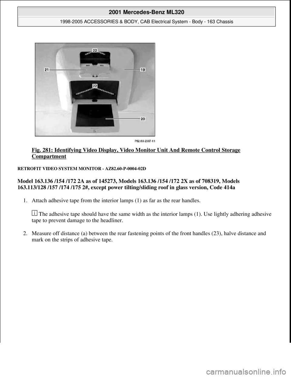
Fig. 281: Identifying Video Display, Video Monitor Unit And Remote Control Storage
Compartment
RETROFIT VIDEO SYSTEM MONITOR - AZ82.60-P-0004-02D
Model 163.136 /154 /172 2A as of 145273, Models 163.136 /154 /172 2X as of 708319, Models
163.113/128 /157 /174 /175 2#, except power tilting/sliding roof in glass version, Code 414a
1. Attach adhesive tape from the interior lamps (1) as far as the rear handles.
The adhesive tape should have the same width as the interior lamps (1). Use lightly adhering adhesive
tape to prevent damage to the headliner.
2. Measure off distance (a) between the rear fastening points of the front handles (23), halve distance and
mark on the strips of adhesive tape.
2001 Mercedes-Benz ML320
1998-2005 ACCESSORIES & BODY, CAB Electrical System - Body - 163 Chassis
me
Saturday, October 02, 2010 3:30:11 PMPage 369 © 2006 Mitchell Repair Information Company, LLC.
Page 1869 of 4133
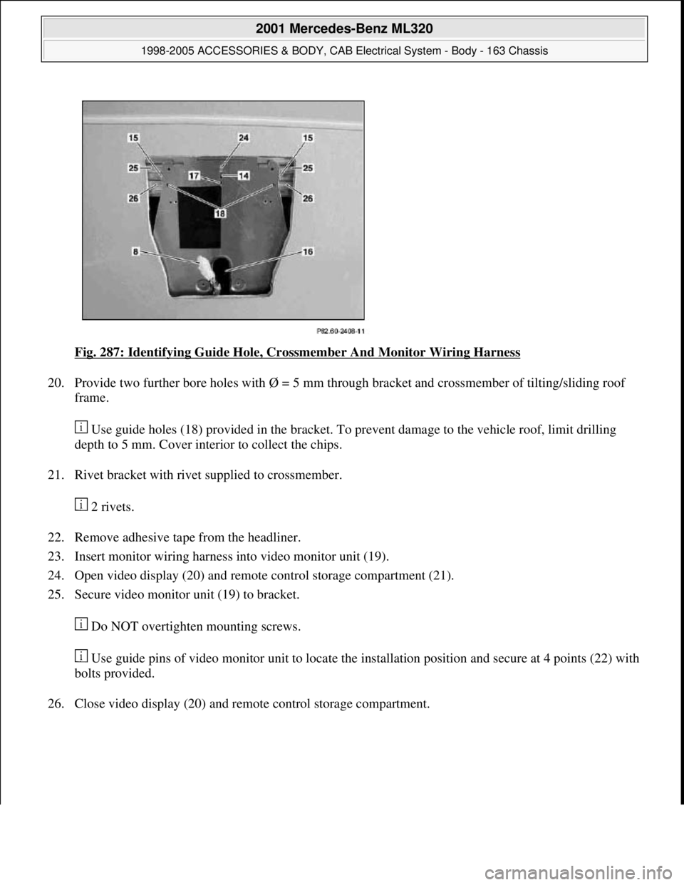
Fig. 287: Identifying Guide Hole, Crossmember And Monitor Wiring Harness
20. Provide two further bore holes with Ø = 5 mm through bracket and crossmember of tilting/sliding roof
frame.
Use guide holes (18) provided in the bracket. To prevent damage to the vehicle roof, limit drilling
depth to 5 mm. Cover interior to collect the chips.
21. Rivet bracket with rivet supplied to crossmember.
2 rivets.
22. Remove adhesive tape from the headliner.
23. Insert monitor wiring harness into video monitor unit (19).
24. Open video display (20) and remote control storage compartment (21).
25. Secure video monitor unit (19) to bracket.
Do NOT overtighten mounting screws.
Use guide pins of video monitor unit to locate the installation position and secure at 4 points (22) with
bolts provided.
26. Close video displa
y (20) and remote control storage compartment.
2001 Mercedes-Benz ML320
1998-2005 ACCESSORIES & BODY, CAB Electrical System - Body - 163 Chassis
me
Saturday, October 02, 2010 3:30:12 PMPage 374 © 2006 Mitchell Repair Information Company, LLC.
Page 1870 of 4133
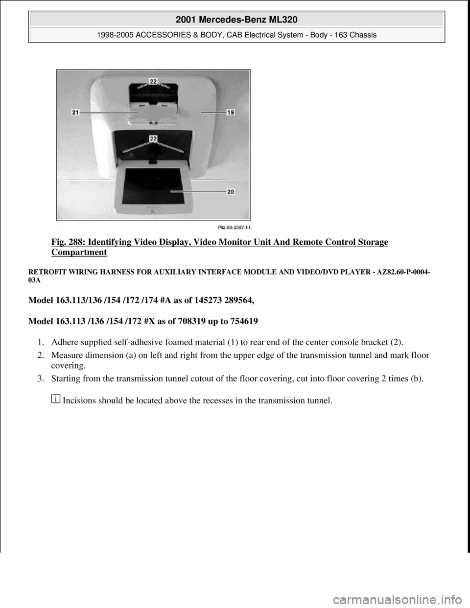
Fig. 288: Identifying Video Display, Video Monitor Unit And Remote Control Storage
Compartment
RETROFIT WIRING HARNESS FOR AUXILIARY INTERFACE MODULE AND VIDEO/DVD PLAYER - AZ82.60-P-0004-
03A
Model 163.113/136 /154 /172 /174 #A as of 145273 289564,
Model 163.113 /136 /154 /172 #X as of 708319 up to 754619
1. Adhere supplied self-adhesive foamed material (1) to rear end of the center console bracket (2).
2. Measure dimension (a) on left and right from the upper edge of the transmission tunnel and mark floor
covering.
3. Starting from the transmission tunnel cutout of the floor covering, cut into floor covering 2 times (b).
Incisions should be located above the recesses in the transmission tunnel.
2001 Mercedes-Benz ML320
1998-2005 ACCESSORIES & BODY, CAB Electrical System - Body - 163 Chassis
me
Saturday, October 02, 2010 3:30:12 PMPage 375 © 2006 Mitchell Repair Information Company, LLC.
Page 2067 of 4133

GF72.29-P-2002GH
Convenience control, function
7.4.97
MODEL
163
The convenience control allows the driver to operate the electrical
seat adjustment, the power windows, the electric vent windows, the
electric outside rearview mirror as well as the electric sliding/pop-up
roof or the electric lamella sliding roof
when the ignition is switched
off.
To achieve this, the all-activity module (AAM) (N10) switches to the
corresponding loads via the convenience relay (F1k14)
circuit 30 .
As of 12.99 the vehicle is equipped with its own convenience relay for
seat adjustment (relay 1, F2k1). In addition the status of the
convenience control via CAN is transmitted to the extended activity
module (EAM, N10/1).
Conditions for control actuation
On all-activity module (AAM) (N10) configured for
I
up
to
11.99:
The convenience actuation becomes active as soon as
D
Circuit 15 ON is recognized
When circuit 15 is switched off, the convenience actuation is
deactivated after a door is opened
Otherwise
The convenience actuation is active in the following cases:
D
Circuit 15c ON
D
A front door is open
D
The remote control key is removed, however, the doors are not
yet opened
In both cases the convenience actuation remains active for 5 min.
Switch-on condition for circuit 15c
When the remote control key is inserted into the ignition lock, circuit
15c is switched on when the key is turned out of the zero position.
Circuit 15c switches off only after the remote control key is removed
from the ignition lock
Electric seat adjustment without memory,
function
GF91.29-P-0003GH
Electric seat adjustment with memory, function
as of 12.99
GF91.29-P-0002GH
Convenience control, function
for electrical seat adjustment as of 12.99
GF91.29-P-2013GK
Power windows, function
GF72.29-P-0003GH
Power tilting/sliding roof (SR), function
GF77.20-P-0001GH
Electrically adjustable outside rearview
mirrors, function
GF88.79-P-0005GH
Electric vent windows, function
GF67.39-P-1000GH
Extended activity module,
location/purpose/design
as of 12.99
GF54.21-P-4107GK
Copyright DaimlerChrysler AG 04.08.2006 CD-Ausgabe G/10/04 . This WIS print-out will not be recorde
d by Modification services.
Page 1
Page 3421 of 4133
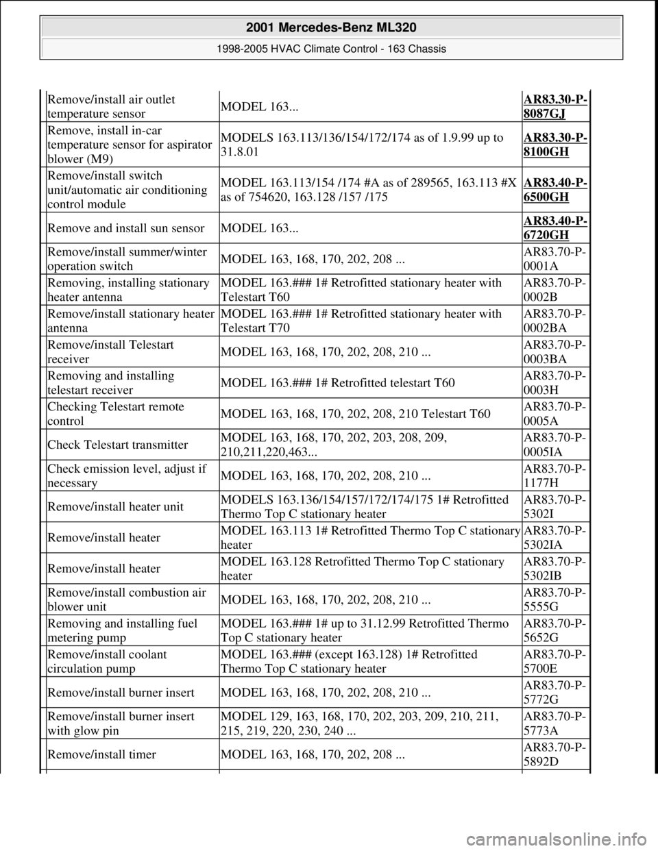
Remove/install air outlet
temperature sensorMODEL 163...AR83.30-P-
8087GJ
Remove, install in-car
temperature sensor for aspirator
blower (M9)MODELS 163.113/136/154/172/174 as of 1.9.99 up to
31.8.01AR83.30-P-
8100GH
Remove/install switch
unit/automatic air conditioning
control moduleMODEL 163.113/154 /174 #A as of 289565, 163.113 #X
as of 754620, 163.128 /157 /175AR83.40-P-
6500GH
Remove and install sun sensorMODEL 163...AR83.40-P-
6720GH
Remove/install summer/winter
operation switchMODEL 163, 168, 170, 202, 208 ...AR83.70-P-
0001A
Removing, installing stationary
heater antennaMODEL 163.### 1# Retrofitted stationary heater with
Telestart T60AR83.70-P-
0002B
Remove/install stationary heater
antennaMODEL 163.### 1# Retrofitted stationary heater with
Telestart T70AR83.70-P-
0002BA
Remove/install Telestart
receiverMODEL 163, 168, 170, 202, 208, 210 ...AR83.70-P-
0003BA
Removing and installing
telestart receiverMODEL 163.### 1# Retrofitted telestart T60AR83.70-P-
0003H
Checking Telestart remote
controlMODEL 163, 168, 170, 202, 208, 210 Telestart T60AR83.70-P-
0005A
Check Telestart transmitterMODEL 163, 168, 170, 202, 203, 208, 209,
210,211,220,463...AR83.70-P-
0005IA
Check emission level, adjust if
necessaryMODEL 163, 168, 170, 202, 208, 210 ...AR83.70-P-
1177H
Remove/install heater unitMODELS 163.136/154/157/172/174/175 1# Retrofitted
Thermo Top C stationary heaterAR83.70-P-
5302I
Remove/install heaterMODEL 163.113 1# Retrofitted Thermo Top C stationary
heaterAR83.70-P-
5302IA
Remove/install heaterMODEL 163.128 Retrofitted Thermo Top C stationary
heaterAR83.70-P-
5302IB
Remove/install combustion air
blower unitMODEL 163, 168, 170, 202, 208, 210 ...AR83.70-P-
5555G
Removing and installing fuel
metering pumpMODEL 163.### 1# up to 31.12.99 Retrofitted Thermo
Top C stationary heaterAR83.70-P-
5652G
Remove/install coolant
circulation pumpMODEL 163.### (except 163.128) 1# Retrofitted
Thermo Top C stationary heaterAR83.70-P-
5700E
Remove/install burner insertMODEL 163, 168, 170, 202, 208, 210 ...AR83.70-P-
5772G
Remove/install burner insert
with glow pinMODEL 129, 163, 168, 170, 202, 203, 209, 210, 211,
215, 219, 220, 230, 240 ...AR83.70-P-
5773A
Remove/install timerMODEL 163, 168, 170, 202, 208 ...AR83.70-P-
5892D
2001 Mercedes-Benz ML320
1998-2005 HVAC Climate Control - 163 Chassis
me
Saturday, October 02, 2010 3:23:17 PMPage 177 © 2006 Mitchell Repair Information Company, LLC.
Page 3520 of 4133
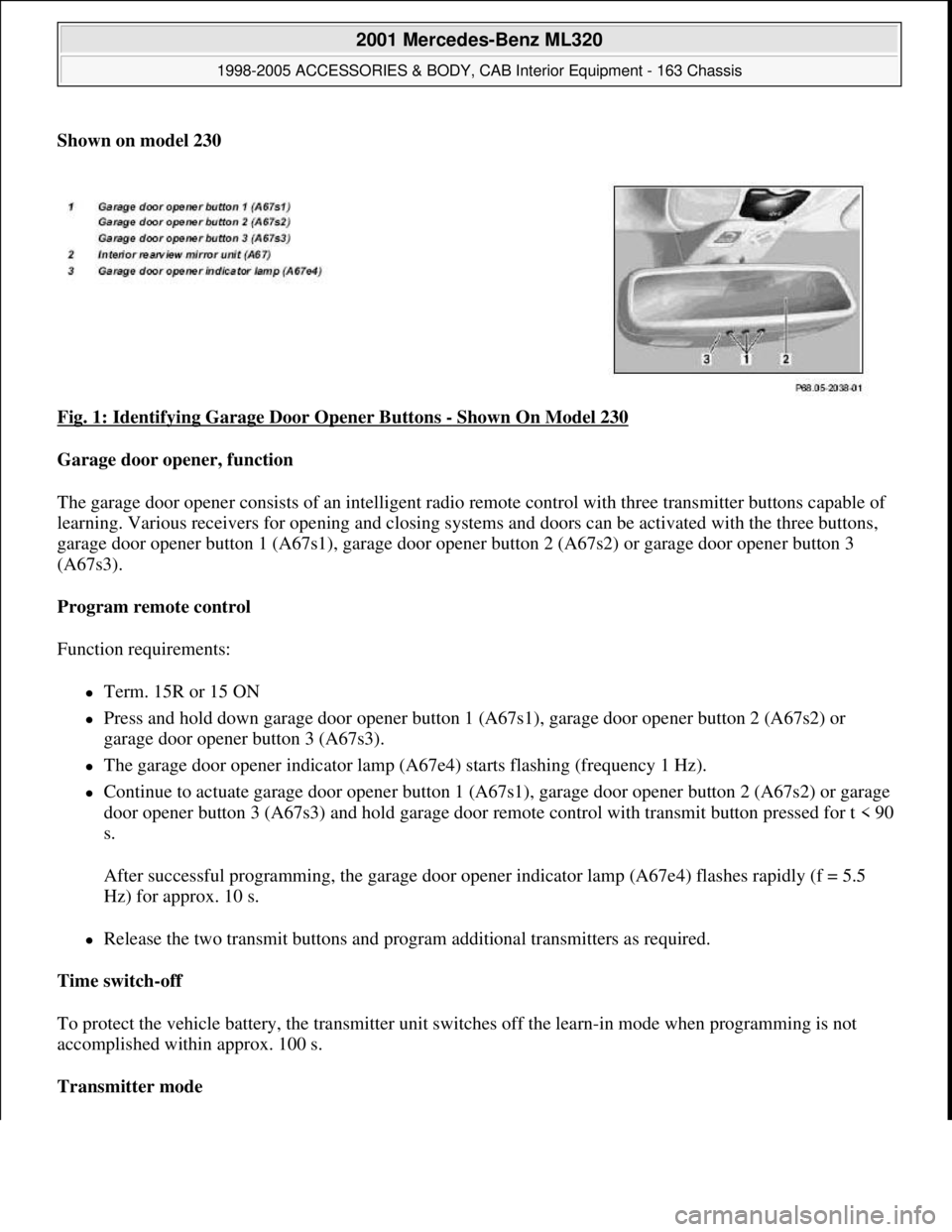
Shown on model 230
Fig. 1: Identifying Garage Door Opener Buttons
- Shown On Model 230
Garage door opener, function
The garage door opener consists of an intelligent radio remote control with three transmitter buttons capable of
learning. Various receivers for opening and closing systems and doors can be activated with the three buttons,
garage door opener button 1 (A67s1), garage door opener button 2 (A67s2) or garage door opener button 3
(A67s3).
Program remote control
Function requirements:
Term. 15R or 15 ON
Press and hold down garage door opener button 1 (A67s1), garage door opener button 2 (A67s2) or
garage door opener button 3 (A67s3).
The garage door opener indicator lamp (A67e4) starts flashing (frequency 1 Hz).
Continue to actuate garage door opener button 1 (A67s1), garage door opener button 2 (A67s2) or garage
door opener button 3 (A67s3) and hold garage door remote control with transmit button pressed for t < 90
s.
After successful programming, the garage door opener indicator lamp (A67e4) flashes rapidly (f = 5.5
Hz) for approx. 10 s.
Release the two transmit buttons and program additional transmitters as required.
Time switch-off
To protect the vehicle battery, the transmitter unit switches off the learn-in mode when programming is not
accomplished within approx. 100 s.
Transmitter mode
2001 Mercedes-Benz ML320
1998-2005 ACCESSORIES & BODY, CAB Interior Equipment - 163 Chassis
me
Saturday, October 02, 2010 3:35:21 PMPage 2 © 2006 Mitchell Repair Information Company, LLC.
Page 3527 of 4133
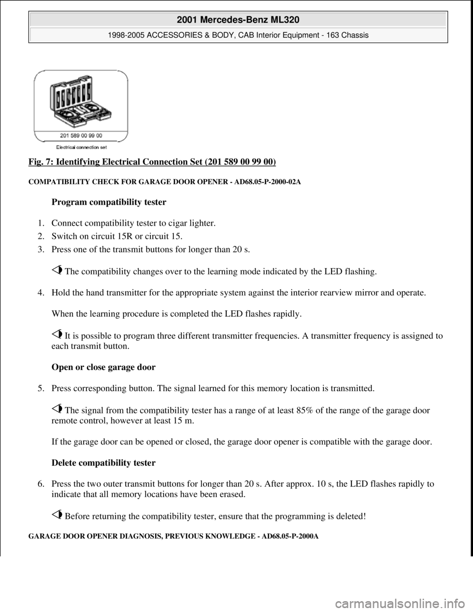
Fig. 7: Identifying Electrical Connection Set (201 589 00 99 00)
COMPATIBILITY CHECK FOR GARAGE DOOR OPENER - AD68.05-P-2000-02A
Program compatibility tester
1. Connect compatibility tester to cigar lighter.
2. Switch on circuit 15R or circuit 15.
3. Press one of the transmit buttons for longer than 20 s.
The compatibility changes over to the learning mode indicated by the LED flashing.
4. Hold the hand transmitter for the appropriate system against the interior rearview mirror and operate.
When the learning procedure is completed the LED flashes rapidly.
It is possible to program three different transmitter frequencies. A transmitter frequency is assigned to
each transmit button.
Open or close garage door
5. Press corresponding button. The signal learned for this memory location is transmitted.
The signal from the compatibility tester has a range of at least 85% of the range of the garage door
remote control, however at least 15 m.
If the garage door can be opened or closed, the garage door opener is compatible with the garage door.
Delete compatibility tester
6. Press the two outer transmit buttons for longer than 20 s. After approx. 10 s, the LED flashes rapidly to
indicate that all memory locations have been erased.
Before returning the compatibility tester, ensure that the programming is deleted!
GARAGE DOOR OPENER DIAGNOSIS, PREVIOUS KNOWLEDGE - AD68.05-P-2000A
2001 Mercedes-Benz ML320
1998-2005 ACCESSORIES & BODY, CAB Interior Equipment - 163 Chassis
me
Saturday, October 02, 2010 3:35:21 PMPage 9 © 2006 Mitchell Repair Information Company, LLC.