1997 MERCEDES-BENZ ML430 change wheel
[x] Cancel search: change wheelPage 3147 of 4133
low-viscosity base oils are not permitted. The kinematic viscosity at 100°C 2 must be at least 9.5 mm /s.
In hot zones, gear oils of SAE grade 90 are also permitted.
2.2 Alternative transmission lubricants for commercial vehicle synchromesh transmissions which are
operated with transmission oils as per sheets 235.1, 235.5.
If there are no gear oils according to Sheet 235.1 and 235.5 available, the following engine oils can also
be used as alternatives:
In a moderate climate, engine oils of SAE-grade 30 as per sheet 235.12
In tropical climate, engine oils of SAE-grade 40 as per sheet 235.12
2.3 Fully synthetic transmission oil, sheet 235.4
Completely synthetic gear oils are imperative for the Unimog manual transmission UG 3/40, UG 3/65 and
the PTO transmission -as of the vehicle end No. ...179909 -. Older vehicles can have their oils changed
from gear oils according to Sheet 235.1 to gear oils according to Sheet 235.4 when an oil change is due.
The gear oils correspond to the ZF lubricant specifications TE-ML01 and TE-ML02 and are consequently
alternatives to the gear oils according to Sheet 235.1 in all synchronized ZF manual transmissions
installed in MB vehicles, with and without intarders. Furthermore, the approval extends to the MB
transfer case VG 2400 without oil cooler. Due to the favorable viscosity/temperature characteristics, a
good cold-shifting response and, due to the composition of the transmission oil, a good thermal/oxidative
stability of the oil at high transmission oil temperatures can be expected.
2.4 Transmission oils, sheet 235.5
The gear oils are approved for MB and ZF manual transmissions with steel/molybdenum synchronization,
MB and ZF transfer cases and corner gears.
The transmission oils have a low chlorine content as well as a potential for lower oil temperatures under
certain operating conditions.
2.5 Transmission oils, sheet 235.10
The partly synthetic gear oils are approved for the commercial vehicle manual transmission Model
G16/G28, for the passenger vehicle front-wheel-drive manual transmission SG 150/180 (A class) as well
as for all passenger vehicle in-line transmissions of the model series 717.4 as of transmission serial
number 7 340 241.
Due to the favorable viscosity/temperature characteristics, a very good cold-shifting response and, due to
the composition of the transmission oil, a good thermal/oxidative stability of the oil at high transmission
oil temperatures can be expected.
With regard to the use in passenger vehicle front-wheel drive manual transmissions/in-line transmissions,
which are also installed in cross-countr
y vehicles, the approved gear oil is usually only used in the event
2004 Mercedes-Benz ML350
1998-2005 GENINFO Overall vehicle - 163 Chassis
me
Saturday, October 02, 2010 3:47:56 PMPage 502 © 2006 Mitchell Repair Information Company, LLC.
Page 3176 of 4133
Because the brake fluid also absorbs moisture through the vent bore on the expansion reservoir, the wheel brake
cylinder and the brake hoses, the brake fluid has to be changed for safety reasons at regular intervals, best done
in the spring. When performing this change, make sure that the old fluid is also drained off the clutch system.
Generally, it is vital for the brake/clutch system to be completely drained before being filled with new fluid!
For the above-mentioned reasons, used brake fluid must not be used again.
The brake fluid is amber in color and thus can be easily confused with mineral products.
Therefore, brake fluids should always only be taken from original containers and stored separately from other
mineral oils and fluids.
When performing maintenance operations and repairs on brake parts, make sure that fuel, mineral oil, grease or
suchlike do not enter the brake system. Hydrocarbon-based materials will lead to swelling of the elastomers in
the brake and clutch system and - even in low concentrations - will suffice to cause total failure of the systems.
Only new brake fluid may be used as a rinsing and cleaning agent for the cylinders, lines and the expansion
reservoir of the hydraulic brake system.
Experience shows that before handling brake fluid, the hands must be cleaned and any oil and grease removed.
Brake fluid acts aggressively towards paint and color. In the event of any brake fluid spills or splashes, it must
be rinsed away immediately using copious amounts of water (do not rub it away).
Brake fluid disposal
When disposing of brake fluid, the relevant national specifications must be observed. It is advisable to try to
have the brake fluid disposed of as economic good; this is contingent on
Strict separation of used brake fluid from other materials;
Presence of a disposal channel, which justifies its classification as an economic good, i.e. a proper
alternate usage must be assured.
If this procedure is not possible, used brake fluid is to be disposed of together with any, e.g. paint residue,
solvents and suchlike. Any adding of used oil must be avoided, as it will result in difficulties, if the used oil is to
be recycled; in several countries this is prohibited by the legislators.
MISCELLANEOUS NOTES
NOTES ON SCRAPPING GAS-FILLED HYDRAULIC COMPONENTS - OS00.00-P-1000-01A
all
Unusable gas pressure dampers, spring accumulators, pressure reservoirs and impact absorbers have to be
depressurized before being scrapped according to the respective valid accident prevention regulations. These
safety measures are necessary because gas pressurized hydraulic parts can explode if heat is applied. A risk of
explosion is
given, e.g. when scrapping with cutting torches, smelting or if gas pressurized parts in landfills start
2004 Mercedes-Benz ML350
1998-2005 GENINFO Overall vehicle - 163 Chassis
me
Saturday, October 02, 2010 3:47:57 PMPage 531 © 2006 Mitchell Repair Information Company, LLC.
Page 3286 of 4133
Control is then carried out there as follows:
Temperature selector wheel MAX setting (full heater output)
Due to the setting of the blending air flaps, the drawn in air is routed through the heat exchanger. Heated
cooling water generally flows through this, as a result of which the passing air is heated. The temperature-
controlled air is guided into the vehicle interior via the various air outlets.
Temperature selector wheel MIN setting (no heater output)
In this setting, the blending air flaps block the route to the heat exchanger. The drawn in fresh air is guided
directly to the air outlets and therefore into the vehicle interior.
HEATER FUNCTIONAL DESCRIPTION TABLE OF CONTENTS - GF83.20-P-0998GH
MODEL 163 up to 31.8.01 except CODE (580) Air conditioning or Tempmatic for USA
Ventilation system function GF83.10-P-2000GH
Heater circuit function GF83.20-P-2003GH
Heater controls, function GF83.20-P-2004GH
Heater function GF83.20-P-0002GH
Ventilation system function GF83.10-P-2000GH
Heater circuit function GF83.20-P-2003GH
Heater controls, function GF83.20-P-2004GH
Air inlet, location/function GF83.10-P-2138GC
Air ducts, location/task/design GF83.10-P-2139GH
Blower, location/task/design/function GF83.10-P-2102GC
Series resistor group, location/task/function GF83.10-P-2161GC
Dust filter, location/task/function GF83.10-P-2142GH
Rear vent, location/task/function GF83.10-P-2143GC
Defroster vent, location/task/function GF83.10-P-2144GC
Center nozzle, location/task/function GF83.10-P-2149GC
Lateral nozzle, location/task/function GF83.10-P-2150GC
Front footwell air outlet, location/task/function GF83.10-P-2145GC
Rear footwell air outlet, location/task/function GF83.10-P-2146GC
Heating system heat exchanger, location/ purpose/function GF83.20-P-2108GC
Fresh air/recirculated air flap, location/task/ function GF83.20-P-2111GC
Fresh air/recirculated air flap actuator, location/ task/function GF83.30-P-2116GC
Blower switch, location/task/design/function GF83.25-P-2100GC
Air distribution switch, location/task/design/ function GF83.25-P-2101GH
Temperature selector wheel, location/task/ design/function GF83.25-P-2102GC
Air recirculation switch, location/task/design/ function GF83.10-P-2117GH
2001 Mercedes-Benz ML320
1998-2005 HVAC Climate Control - 163 Chassis
me
Saturday, October 02, 2010 3:23:15 PMPage 42 © 2006 Mitchell Repair Information Company, LLC.
Page 3288 of 4133
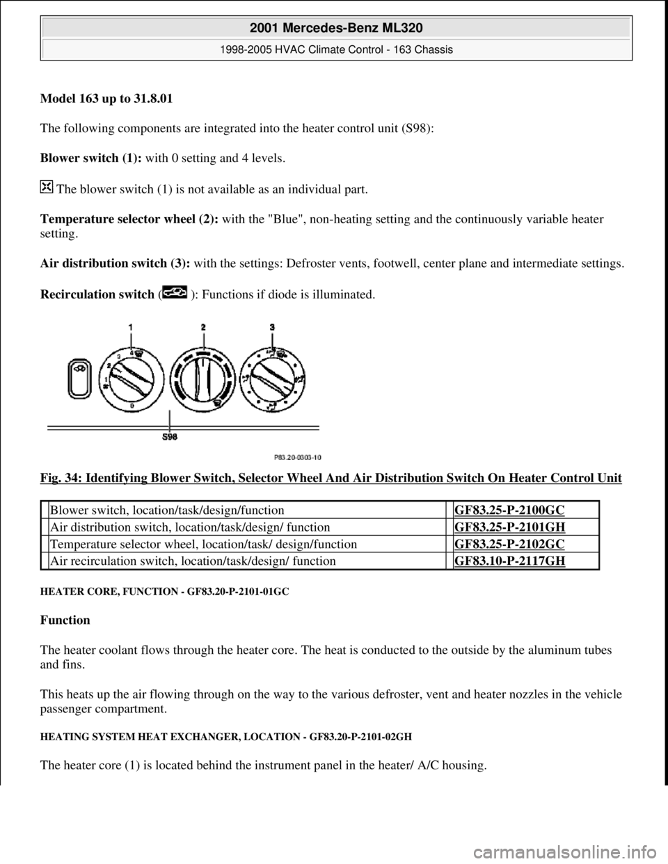
Model 163 up to 31.8.01
The following components are integrated into the heater control unit (S98):
Blower switch (1): with 0 setting and 4 levels.
The blower switch (1) is not available as an individual part.
Temperature selector wheel (2): with the "Blue", non-heating setting and the continuously variable heater
setting.
Air distribution switch (3): with the settings: Defroster vents, footwe ll, center plane and intermediate settings.
Recirculation switch ( ): Functions if diode is illuminated.
Fig. 34: Identifying Blower Switch, Selector Wheel And Air Distribution Switch On Heater Control Unit
HEATER CORE, FUNCTI ON - GF83.20-P-2101-01GC
Function
The heater coolant flows through the heater core. The he at is conducted to the outside by the aluminum tubes
and fins.
This heats up the air flowing through on the way to the vari ous defroster, vent and heater nozzles in the vehicle
passenger compartment.
HEATING SYSTEM HEAT EXCHANGE R, LOCATION - GF83.20-P-2101-02GH
The heater core (1) is located behind the instrument panel in the heater/ A/C housing.
Blower switch, location/task/design/function GF83.25-P-2100GC
Air distribution switch, locat ion/task/design/ function GF83.25-P-2101GH
Temperature selector wheel, location/task/ design/function GF83.25-P-2102GC
Air recirculation switch, loca tion/task/design/ function GF83.10-P-2117GH
2001 Mercedes-Benz ML320
1998-2005 HVAC Climate Control - 163 Chassis
me
Saturday, October 02, 2010 3:23:15 PMPage 44 © 2006 Mitchell Repair Information Company, LLC.
Page 3304 of 4133
After starting, the refrigerant compressor starts up. If cooling is not necessary, the refrigerant compressor's
output is lowered and switched off via the icing inhibitor.
The air conditioning is always ready for operation after the engine has been started, and operates according to
the so-called "reheat" principle. This means: The refrigerant compressor always operates at an ambient
temperature in excess of 1°C, therefore also cools cold incoming air. Following the cooling process, the dried
air is heated at the heat exchanger.
On the one hand, this effect serves the purpose of comfort, because cooling also simultaneously causes air
dehumidification which, in turn, is an important prerequisite for a pleasant interior climate. On the other hand,
the air is dried as a result of this cooling and heating, thereby preventing window fogging.
Pressing the AC button again ( ) (does not illuminate) switches off the cooling.
Heating mode
The in-car temperature sensor measures the air temperature in the interior of the vehicle.
The air conditioning control module electronics compares the in-car temperature with the desired temperature
which has been set at the temperature selector wheels.
The microprocessor adjusts the air conditioning electronics or keeps the relevant setting constant as required.
Heater operation with heater booster in vehicles with engine 612.963 as of 12/99
In vehicles equipped with direct-injection diesel engines, an electrical heater booster is additionally installed in
the evaporator housing downstream of the heat exchanger, in order to compensate any heater output deficit
which exists under certain operating conditions.
The 3 heating elements in the heater booster are supplied with current, whereupon they are heated and they start
to glow. As a result of the structural conditions, it is ensured that the drawn in fresh air flows directly past the
electric heater booster, and is therefore heated.
Cooling mode
The icing inhibitor measures the temperature at the evaporator air outlet, while the interior temperature sensor
determines the relevant in-car temperature.
The air conditioning control module electronics compares the various measured values with the desired
temperature which has been set at the temperature selector wheels.
The microprocessor adjusts the air conditioning or keeps the relevant setting constant as required.
In-car temperature sensor replaced by new typeas of 1.12.99BT83.57-P-0001-04GH
Ventilation, function GF83.10-P-2000GH
Heater circuit function GF83.20-P-2003GH
2001 Mercedes-Benz ML320
1998-2005 HVAC Climate Control - 163 Chassis
me
Saturday, October 02, 2010 3:23:15 PMPage 60 © 2006 Mitchell Repair Information Company, LLC.
Page 3323 of 4133
Lateral nozzle, location/purpose/function GF83.10-P-
2150GC
Front footwell air outlet, location/purpose/ function GF83.10-P-
2145GC
Rear footwell air outlet, location/purpose/ function GF83.10-P-
2146GC
Heating system heat exchanger, location/
purpose/function GF83.20-P-
2108GC
Fresh air/recirculation flap, location/purpose/ function GF83.20-P-
2111GC
Fresh air/recirculation flap actuator, location/
purpose/function GF83.30-P-
2116GC
Blower switch, location/purpose/design/function GF83.25-P-
2100GC
Air distribution switch, location/purpose/design/
function GF83.25-P-
2101GH
Temperature selector wheel, location/purpose/
design/function GF83.25-P-
2102GC
Air recirculation switch, location/purpose/
design/function GF83.10-P-
2117GH
AC button, location/purpose/function GF83.30-P-
2103GH
AC control module, location/purpose/function GF83.30-P-
2102GH
All-activity module, location/purpose/function GF54.21-P-
4110GH
A/C housing, location/purpose/function GF83.30-P-
2119GH
Auxiliary fan, location/purpose/functionENGINE 111.977, 112.942GF83.40-P-
2162GH
Electric fan motor/air conditioning system,
location/purpose/functionEngine 113.942, 113.981 and
612.963, 628.963GF83.40-P-
2151GH
Condenser, location/purpose/function GF83.40-P-
2152GC
Evaporator location/purpose/design/function GF83.40-P-
2121GC
Fluid reservoir (TAC), location/purpose/function GF83.30-P-
2120GC
Expansion valve, location/purpose/design/ function GF83.40-P-
2123GC
Refrigerant pressure sensor, location/purpose/ function GF83.40-P-
2156GH
Refrigerant compressor, location/purpose/
design/function GF83.55-P-
2100GH
2001 Mercedes-Benz ML320
1998-2005 HVAC Climate Control - 163 Chassis
me
Saturday, October 02, 2010 3:23:15 PMPage 79 © 2006 Mitchell Repair Information Company, LLC.
Page 3362 of 4133
function 2146GI
Blower motor,
location/purpose/design/function GF83.10-P-
2170GI
Blower regulator, location/purpose/function GF83.10-P-
2141GI
Rear blower motor, location/purpose/design/
function GF83.10-P-
2168GI
Rear electronic blower regulator, location/
purpose/function GF83.10-P-
2176GI
Combination filter, location/purpose/function GF83.10-P-
2128GI
Defroster vent flap actuator motor, location/
purpose/function GF83.10-P-
2175GI
Footwell flap actuator,
location/purpose/function GF83.10-P-
2132GI
Actuator motor, center nozzle flap, location/
purpose/function GF83.10-P-
2172GI
Actuator motor, rear shut-off flap, location/
purpose/function GF83.10-P-
2171GI
Actuator motor, rear air distribution flap,
location/purpose/function GF83.10-P-
2173GI
Heating system heat exchanger, location/
purpose/function GF83.20-P-
2108GC
Heating water circulation pump, location/
purpose/function GF83.20-P-
2109GI
Fresh air/recirculation flap, location/purpose/
function GF83.20-P-
2111GC
Fresh air/recirculation flap actuator, location/
purpose/function GF83.30-P-
2116GC
Blower switch,
location/purpose/design/function GF83.25-P-
2100GI
Blower button, location/purpose/functionRear ventilation operating moduleGF83.40-P-
2144GI
Air distribution switch,
location/purpose/design/ function GF83.25-P-
2101GI
Air distribution button,
location/purpose/functionRear ventilation operating moduleGF83.40-P-
2159GI
Temperature selector wheel, location/purpose/
design/function GF83.25-P-
2102GI
Defroster button, location/purpose/function GF83.40-P-
2139GI
Recirculating air push-button,
location/purpose/ function GF83.40-P-
2145GI
GF83.40-P-
2001 Mercedes-Benz ML320
1998-2005 HVAC Climate Control - 163 Chassis
me
Saturday, October 02, 2010 3:23:16 PMPage 118 © 2006 Mitchell Repair Information Company, LLC.
Page 3381 of 4133
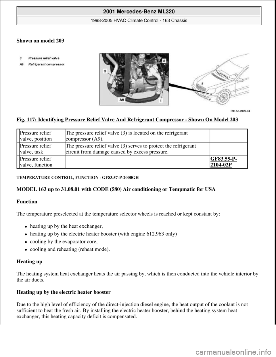
Shown on model 203
Fig. 117: Identifying Pressure Relief Valve And Refrigerant Compressor
- Shown On Model 203
TEMPERATURE CONTROL, FUNCTION - GF83.57-P-2000GH
MODEL 163 up to 31.08.01 with CODE (580) Air conditioning or Tempmatic for USA
Function
The temperature preselected at the temperature selector wheels is reached or kept constant by:
heating up by the heat exchanger,
heating up by the electric heater booster (with engine 612.963 only)
cooling by the evaporator core,
cooling and reheating (reheat mode).
Heating up
The heating system heat exchanger heats the air passing by, which is then conducted into the vehicle interior by
the air ducts.
Heating up by the electric heater booster
Due to the high level of efficiency of the direct-injection diesel engine, the heat output of the coolant is not
sufficient to heat the fresh air. By installing the electric heater booster, behind the heating system heat
exchanger, this heating capacity deficit is compensated.
Pressure relief
valve, positionThe pressure relief valve (3) is located on the refrigerant
compressor (A9).
Pressure relief
valve, taskThe pressure relief valve (3) serves to protect the refrigerant
circuit from damage caused by excess pressure.
Pressure relief
valve, function GF83.55-P-
2104-02P
2001 Mercedes-Benz ML320
1998-2005 HVAC Climate Control - 163 Chassis
me
Saturday, October 02, 2010 3:23:17 PMPage 137 © 2006 Mitchell Repair Information Company, LLC.