1997 MERCEDES-BENZ ML430 change wheel
[x] Cancel search: change wheelPage 1569 of 4133
4-channel power amplifier for vehicle loudspeakers
System interlinkage
The radio and navigation unit (A2/56) is provided with the following components for data exchange with
external digital components:
CAN (A1 -A2/56)
The radio and navigation unit (A2/56) is connected with the instrument cluster (A1) via a separate
CAN bus. The difference to the other CAN systems is indicated by the spelling CAN bus (A1-A2/56).
The CAN bus (A1-A2/56) allows the following functions:
Operation of the radio and navigation unit (A2/56)is also possible with the multifunction steering
wheel.
The multifunction display (A1/p13) in the instrument cluster (A1) can display navigation
information on the current operating status of the radio and navigation unit (A2/56) .
The connection to the CAN bus (A1-A2/56) is only realized on models 208 and 210. (Status 3/99)
Digital data bus (D2B)
Data can be exchanged between the external audio components, the telephone system and - if present -
the voice control system over the D2B bus. This allows control data as well as the actual audio signals
(e.g. music from CD changer) to be transferred.
The only additional D2B component presently possible is the CD changer (A2/6) (Status: 3/99)
K bus (diagnostic interface)
Data exchange is accomplished between the diagnostic interface and the hand-held tester (reading out
DTCs and actual values, ...).
The communication between the HHT and all other D2B components is accomplished over the radio
and navigation unit (A2/56) diagnostic interface.
Audio 30 APS, location of
componentsModel 163GF82.61-P-0002-01D
Model 168GF82.61-P-0002-01B
Model 170GF82.61-P-0002-01A
Model 208, model 210&.2.(GF82.61-P-0002-
01C)
Audio 30 APS block
diagramModel 163GF82.61-P-0002-02D
Model 168GF82.61-P-0002-02B
2001 Mercedes-Benz ML320
1998-2005 ACCESSORIES & BODY, CAB Electrical System - Body - 163 Chassis
me
Saturday, October 02, 2010 3:30:05 PMPage 74 © 2006 Mitchell Repair Information Company, LLC.
Page 1577 of 4133
The navigation processor recognizes the direction of motion (forward or reverse) from the reverse signal.
Direction in which vehicle is pointing
From the data of the gyrosensor and the sequence of the locations calculated with GPS the navigation
processor the calculates the direction in which the vehicle is pointing (compass direction).
The difference between calculated and actual distance traveled between two turning points is used for automatic
recalibration of the tire circumference (required due to tire wear).
Location finding errors during basic location finding
Rolling backwards without the reverse gear engaged is evaluated as forward motion, and may lead to an error in
the location finding.
Rolling with the ignition switched off or vehicle transportation also falsify map matching.
In both cases the deviation is automatically corrected by the navigation processor after receiving GPS data .
Calibration
Wheel calibration is not required following tire change.
GLOBAL POSITIONING SYSTEM LOCATION FINDING, FUNCTION - GF82.61-P-3007C
MODEL 163, 168, 170, 203.0 /2 /7, 208, 209.3 /4, 210 with CODE (353) Audio 30 APS
Basic representation of the GPS location finding shown on model 210
Global positioning system
location finding, function GF82.61-P-3007GI
Map-supported location
finding, function GF82.61-P-3008GI
Guidance, function GF82.61-P-3012GI
Radio and navigation
module, location/purpose/
design/function GF82.61-P-4109GI
2001 Mercedes-Benz ML320
1998-2005 ACCESSORIES & BODY, CAB Electrical System - Body - 163 Chassis
me
Saturday, October 02, 2010 3:30:05 PMPage 82 © 2006 Mitchell Repair Information Company, LLC.
Page 1710 of 4133
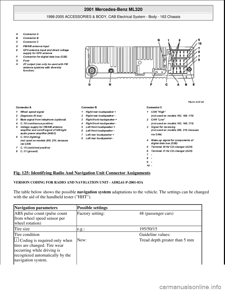
Fig. 125: Identifying Radio And Navigation Unit Connector Assignments
VERSION CODING FOR RADIO AND NAVIGATION UNIT - AD82.61-P-2001-03A
The table below shows the possible navigation system adaptations to the vehicle. The settings can be changed
with the aid of the handheld tester ("HHT").
Navigation parametersPossible settings
ABS pulse count (pulse count
from wheel speed sensor per
wheel rotation)Factory setting:48 (passenger cars)
Tire sizee.g.:195/50/15
Tire condition Guideline values:
Coding is required only when
tires are changed. Tire wear
occurring while driving is
recognized automatically by the
navigation system.New:Tread depth greater than 5 mm
2001 Mercedes-Benz ML320
1998-2005 ACCESSORIES & BODY, CAB Electrical System - Body - 163 Chassis
me
Saturday, October 02, 2010 3:30:08 PMPage 215 © 2006 Mitchell Repair Information Company, LLC.
Page 1830 of 4133
5Navigation menuCall up navigation menu by
pressing NAV buttonLANGUAGE POS
TIME WHEEL
6Erase initial calibration Applies only if unit has
been calibrated initially.
By turning on the right
control knob (10) select
menu "ENTER
ADDRESS" and confirm
by pressing control knob
(10).
Press multifunction key 2,
then 7 and release
simultaneousl
y. Press CAL
multifunction key.
CAL
By turning the right control
knob (10) select menu
"ERASE CALIBRATION"
and confirm by pressing the
control knob (10).After a certain waiting
time the basic
navigation menu
appears
7Start-upPark vehicle outside with
Audio 30 APS switched on
(minimum time for receiving
GPS satellite signals approx.
30 min.).
Call up navigation menu by
pressing NAV buttonLANGUAGE POS
TIME WHEEL
8Select languageSelect desired language by
pressing the multifunction
key "SPRA"
9Enter tire sizeEnter the tire size by
pressing the multifunction
key "WHEEL" and confirm
by pressing the right control
knob (10)
10Perform calibration
drive The duration of the
calibration drive depends on
the vehicle model and
number of changes in
direction. It can be between
30 km and 100 km and can
be interrupted at any time
for as long as desired.
Drive Audio 30 APS at least
300 meters straight ahead in
the radio mode and then turn
correctly to the right or left
2001 Mercedes-Benz ML320
1998-2005 ACCESSORIES & BODY, CAB Electrical System - Body - 163 Chassis
me
Saturday, October 02, 2010 3:30:11 PMPage 335 © 2006 Mitchell Repair Information Company, LLC.
Page 2061 of 4133
AP40.10-P-4051Z
Check tires for damage and cracks
MODEL
123, 124, 126, 129, 140, 163, 168, 170, 171, 201, 202, 203, 208, 209, 210, 211, 215, 220, 230, 240, 414
P40.10-0002-01
P40.10-0001-01
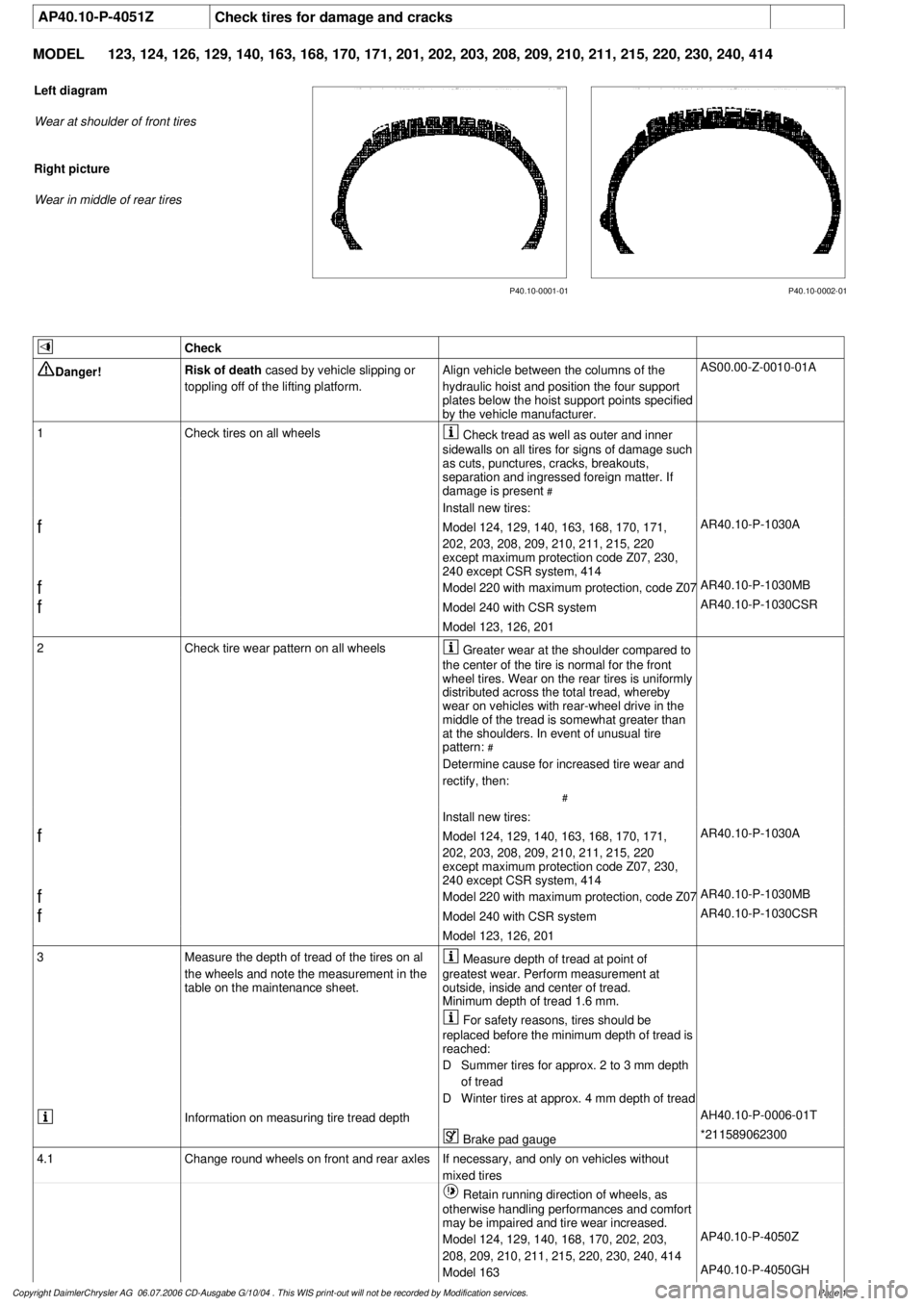
Left diagram
Wear at shoulder of front tires
Right picture
Wear in middle of rear tires
Check
Danger!
Risk of death
cased by vehicle slipping or
toppling off of the lifting platform.
Align vehicle between the columns of the
hydraulic hoist and position the four support
plates below the hoist support points specified
by the vehicle manufacturer.
AS00.00-Z-0010-01A
1
Check tires on all wheels
Check tread as well as outer and inner
sidewalls on all tires for signs of damage such
as cuts, punctures, cracks, breakouts,
separation and ingressed foreign matter. If
damage is present
#
Install new tires:
f
Model 124, 129, 140, 163, 168, 170, 171,
202, 203, 208, 209, 210, 211, 215, 220
except maximum protection code Z07, 230,
240 except CSR system, 414
AR40.10-P-1030A
f
Model 220 with maximum protection, code Z07
AR40.10-P-1030MB
f
Model 240 with CSR system
AR40.10-P-1030CSR
Model 123, 126, 201
2
Check tire wear pattern on all wheels
Greater wear at the shoulder compared to
the center of the tire is normal for the front
wheel tires. Wear on the rear tires is uniformly
distributed across the total tread, whereby
wear on vehicles with rear-wheel drive in the
middle of the tread is somewhat greater than
at the shoulders. In event of unusual tire
pattern:
#
Determine cause for increased tire wear and
rectify, then:
#
Install new tires:
f
Model 124, 129, 140, 163, 168, 170, 171,
202, 203, 208, 209, 210, 211, 215, 220
except maximum protection code Z07, 230,
240 except CSR system, 414
AR40.10-P-1030A
f
Model 220 with maximum protection, code Z07
AR40.10-P-1030MB
f
Model 240 with CSR system
AR40.10-P-1030CSR
Model 123, 126, 201
3
Measure the depth of tread of the tires on al
the wheels and note the measurement in the
table on the maintenance sheet.
Measure depth of tread at point of
greatest wear. Perform measurement at
outside, inside and center of tread.
Minimum depth of tread 1.6 mm.
For safety reasons, tires should be
replaced before the minimum depth of tread is
reached:
D
Summer tires for approx. 2 to 3 mm depth
of tread
D
Winter tires at approx. 4 mm depth of tread
Information on measuring tire tread depth
AH40.10-P-0006-01T
Brake pad gauge
*211589062300
4.1
Change round wheels on front and rear axles
If necessary, and only on vehicles without
mixed tires
Retain running direction of wheels, as
otherwise handling performances and comfort
may be impaired and tire wear increased.
Model 124, 129, 140, 168, 170, 202, 203,
208, 209, 210, 211, 215, 220, 230, 240, 414
AP40.10-P-4050Z
Model 163
AP40.10-P-4050GH
Copyright DaimlerChrysler AG 06.07.2006 CD-Ausgabe G/10/04 . This WIS print-out will not be recorde
d by Modification services.
Page 1
Page 2523 of 4133
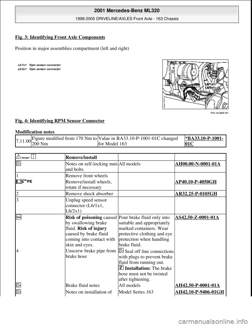
Fig. 3: Identifying Front Axle Components
Position in major assemblies compartment (left and right)
Fig. 4: Identifying RPM Sensor Connector
Modification notes
7.11.00Figure modified from 170 Nm to
200 NmValue in BA33.10-P-1001-01C changed
for Model 163*BA33.10-P-1001-
01C
Remove/install
Notes on self-locking nuts
and boltsAll modelsAH00.00-N-0001-01A
1Remove front wheels
Remove/install wheels,
rotate if necessaryAP40.10-P-4050GH
2Remove shock absorber AR32.25-P-0105GH
3Unplug speed sensor
connector (L6/1x1,
L6/2x1)
Risk of poisoning caused
by swallowing brake
fluid. Risk of injury
caused by brake fluid
coming into contact with
skin and eyes.Pour brake fluid only into
suitable and appropriately
marked containers. Wear
protective clothing and eye
protection when handling
brake fluid.AS42.50-Z-0001-01A
4Unscrew brake pipe from
brake hoseSeal off line connections
with plugs to prevent brake
fluid from running out.
Installation: The brake
hose must not be twisted
after tightening.
Brake fluid notesAll modelsAH42.50-P-0001-01A
Notes on installation of Model Series 163AH42.10-P-9406-01GH
2001 Mercedes-Benz ML320
1998-2005 DRIVELINE/AXLES Front Axle - 163 Chassis
me
Saturday, October 02, 2010 3:38:21 PMPage 4 © 2006 Mitchell Repair Information Company, LLC.
Page 2541 of 4133
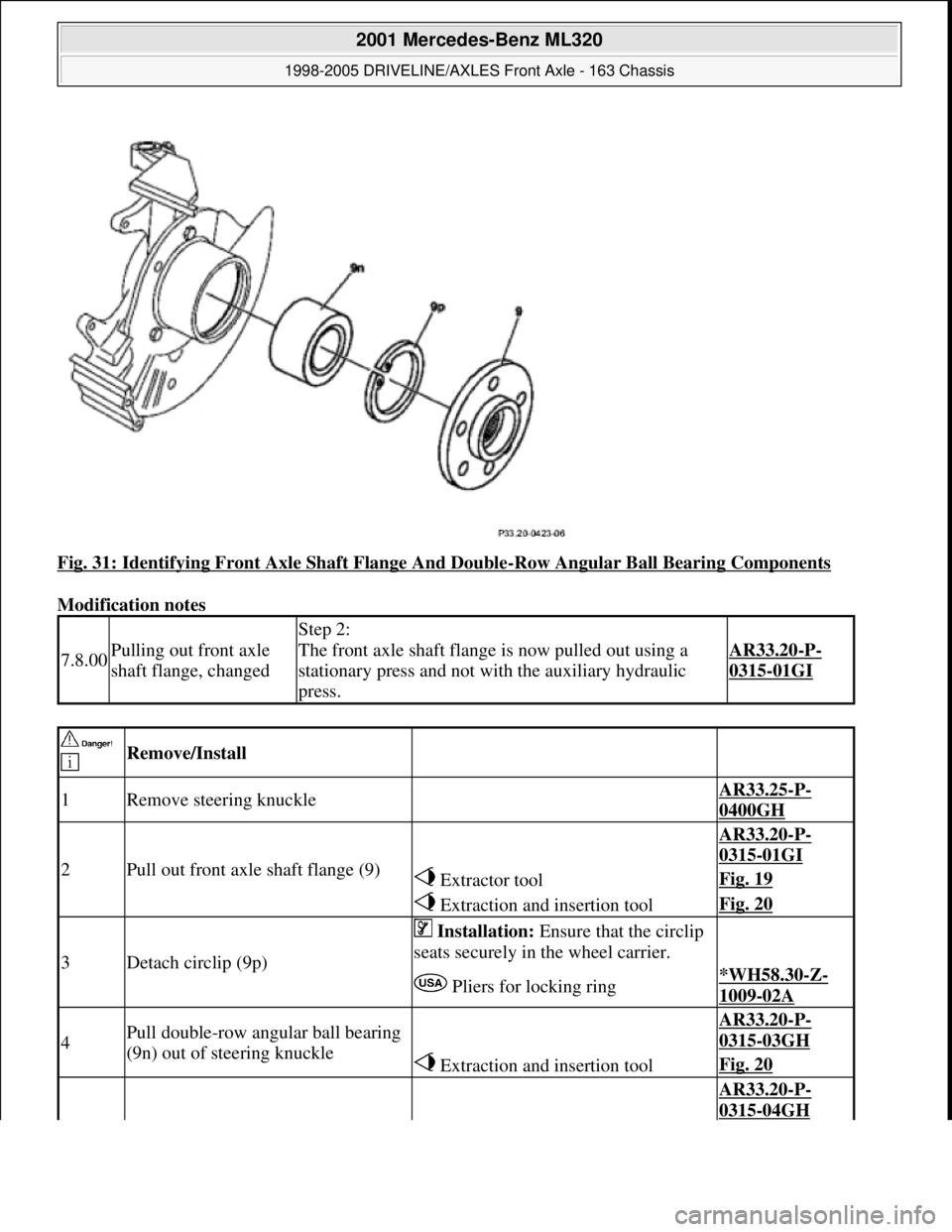
Fig. 31: Identifying Front Axle Shaft Flange And Double-Row Angular Ball Bearing Components
Modification notes
7.8.00Pulling out front axle
shaft flange, changed
Step 2:
The front axle shaft flange is now pulled out using a
stationary press and not with the auxiliary hydraulic
press.
AR33.20-P-
0315-01GI
Remove/Install
1Remove steering knuckle AR33.25-P-
0400GH
2Pull out front axle shaft flange (9)
AR33.20-P-
0315-01GI
Extractor toolFig. 19
Extraction and insertion toolFig. 20
3Detach circlip (9p)
Installation: Ensure that the circlip
seats securely in the wheel carrier.
Pliers for locking ring*WH58.30-Z-
1009-02A
4Pull double-row angular ball bearing
(9n) out of steering knuckle AR33.20-P-
0315-03GH
Extraction and insertion toolFig. 20
AR33.20-P-
0315-04GH
2001 Mercedes-Benz ML320
1998-2005 DRIVELINE/AXLES Front Axle - 163 Chassis
me
Saturday, October 02, 2010 3:38:22 PMPage 22 © 2006 Mitchell Repair Information Company, LLC.
Page 3056 of 4133
modification kit, code U47
except styling package, U49
Engine 612.963 in model 163.113 except
modification kit, code U47
except styling package, U49
Engine 628.963 in model 163.128 except
modification kit, code U47
except styling package, U49
AZ82.20-P-0001B Retrofit illuminated
door sill moldingModel 163.113/128/136/154/172/174/175AZ82.20-P-0001B
AZ82.64-P-
0001MA
Retrofitting CD
changerModel 163 as of 1.7.99 along with Audio
10 radio, Audio 30 or COMAND operating
and display unit and D2B fiber optic cableAZ82.64-P-
0001MA
AZ82.70-P-0002A Retrofitting
permanently
installed D-network
telephoneModel 163 up to 30.11.99 Permanently
installed Nokia 6081 telephoneAZ82.70-P-0002A
AZ82.70-P-0002C Retrofitting
permanently
installed D-network
telephoneModel 163 as of 1.12.99 up to 31.8.00
Telephone fixed installation Nokia 6090AZ82.70-P-0002C
AZ82.70-P-
0002GH
Retrofitting
permanently
installed D-network
telephoneModel 163 from 1.9.00 to 30.9.01 except
code 352a, COMAND operating and
display unit, fixed-installation Nokia 6090
telephoneAZ82.70-P-
0002GH
AZ82.70-P-0001A Retrofit D-network
cell phoneModel 163 up to 30.11.99 permanently
installed Nokia 3110 cell phoneAZ82.70-P-0001A
AZ82.70-P-0001D Retrofit D-network
cell phoneModel 163 as of 1.12.99 up to 31.8.00
Portable CTEL Nokia 3110AZ82.70-P-0001D
AZ82.70-P-
0001GH
Retrofit D-network
cell phoneModel 163 as of 1.10.01, only for D-
network portable CTELAZ82.70-P-
0001GH
AZ88.30-P-0002A Retrofitting outer
spare wheel holderModels 163.113/128/136/154/172/175,
except styling package, code U49AZ88.30-P-0002A
AZ82.60-P-0004A Retrofit vehicle
video systemModels 163.136 /154 /172 1A as of
145273, 163.136/154/172 1X as of 708319,
163.113/128/157/174/175 1# left-hand
drive vehicleAZ82.60-P-0004A
AZ82.60-P-0004BRetrofit vehicle
video systemModels 163.136 /154 /172 2A as of
145273, 163.136 /154 /172 2X as of
708319, 163.113/128 /157 /174 /175 2#
right-hand drive vehicleAZ82.60-P-0004B
AZ88.30-P-
0006GH
Retrofit side step barModels 163.113 /128 /136 /154 /172 /175,
except styling package, code U49AZ88.30-P-
0006GH
AZ88.30-P-
0005GHRetrofit protective
side moldingModels 163.113/128/136/154/172/175,
except styling package, code U49AZ88.30-P-
0005GH
2004 Mercedes-Benz ML350
1998-2005 GENINFO Overall vehicle - 163 Chassis
me
Saturday, October 02, 2010 3:47:52 PMPage 411 © 2006 Mitchell Repair Information Company, LLC.