1997 MERCEDES-BENZ ML430 change wheel
[x] Cancel search: change wheelPage 1142 of 4133
338 IndexTele Aid* 171
Emergency calls 173
Information 177
Initiating an emergency call
manually 175
Remote door unlock 179
Roadside assistance 175
Stolen vehicle tracking services 180
System self-check 172
Upgrade signals 178
Telematics* 315
Telephone* 170
Temperature
Grades of tires 309
Tires 228
Third row seats* 102
Folding down single seat 102
Installing single seat 104
Removing single seat 104
Storing single seat 103
Tie-down rings (Cargo
compartment) 158Tightening torque 315
Tightening torque (Wheel bolts) 277
Tilt
Head restraint 37, 39
Time
Setting hours 118
Setting minutes 118
Tire inflation pressure
Checking 216, 227
Tire speed rating 198, 315
Tire traction 197
Tires 295, 308
Direction of rotation 227
Driving instructions 196
Retreads 226
Rims and tires 295
Rotating 228
Service life 227
Temperature 228
Temperature grades 309
Tread depth 230
Wear pattern 228
Winter 230Tools 257
Vehicle jack 258
Vehicles with CD-changer* 258
Wheel bolt wrench 258
Tow-away alarm 29, 84
Arming 84
Disarming 84
Disarming for transport 84
Towing
Trailer 206
Towing a trailer 209
Automatic transmission 124
Towing eyes
Front 285
Rear 285
Towing the vehicle 283
Stranded vehicle 286
Tracking services
For stolen vehicle 180
Page 1144 of 4133
340 IndexUseful features 164
Ashtrays and cigarette lighter 168
Cup holder 166
Electrical outlet 170
Garage door opener 180
Interior storage spaces 164
Programming or reprogramming the in-
tegrated remote control 182
Tele Aid* 171
Telephone* 170
Trip computer* 186
V
Vehicle
Locking 28
Locking in an emergency 262
Lowering 276
Proper use of 17
Service battery 278
Towing 283
Unlocking 28
Unlocking in an emergency 261
Vehicle and trailer weights and
ratings 207
Vehicle battery 278Vehicle care
Cup holder 238
Engine cleaning 236
Gear selector lever 238
Hard plastic trim items 238
Headlamps 236
Instrument cluster 238
Leather upholstery 239
Light alloy wheels 238
MB Tex upholstery 239
Ornamental moldings 236
Paintwork 235
Parktronic* system sensor 237
Plastic and rubber parts 239
Power washer 235
Seat belts 238
Steering wheel 238
Tail lamps 236
Tar stains 235
Turn signals 236
Upholstery 239
Vehicle washing 236
Window cleaning 237
Wiper blades 237Vehicle identification number (VIN) 292
Vehicle jack 258
Vehicle lighting
Checking 216
Vehicle tool kit 257
Vehicle with CD-changer* 258
Vehicle washing 236
VIN (Vehicle Identification Number) 292,
315
Voice control system* 315
W
Warning indicators
Parktronic* 155
Warning sounds
Drivers seat belts 64
Parking brake 48
Warranty coverage 291
Washer fluid see Windshield washer fluid
Washing the vehicle 234
Page 1145 of 4133

341 Index
Wear pattern (tires) 228
Weights 299
Wheel bolt wrench 258
Wheel change
Tightening torque 277
Wheels
Rotating 228
Window curtain airbags 64
Windows see Side windows
Windshield
Defogging 138
Refilling washer fluid 224
Replacing wiper blades 273
Washer fluid 224, 307
Washer system 307
Windshield washer fluid 307
Filler neck 224
Mixing ratio 307
Refilling 224
Wiping with 50Windshield washer system 307
Windshield wipers 49, 129
Intermittent 49
Interval wiping 130
Normal wiper speed 49
Rain sensor* 130
Rear window wiper/washer 51
Replacing wiper blades 273
Simultaneous wiping and washing 51
Single wipe 50
Switching on 49
Wiping with windshield washer
fluid 50
Winter driving
Snow chains 231
Tires 230
Winter driving instructions 198
Winter tires 230Wiper blades
Cleaning 237
Installing 273
Removing 273
Replacing 273
Wiper switch 49
Wiper/washer
Rear window 51
Wiping
And washing simultaneously 50
Intermittent 49, 130
With windshield washer fluid 50
Wiping and washing simultaneously 51
X
Xenon headlamps*
Bi-Xenon* 311
Page 1246 of 4133
Operation - If the inner race (13) of the freewheel is locked and the outer race (12) turns in direction "A" , the
locking elements (14) adopt a diagonal position on account of their special contours, allowing the freewheel
function. See Fig. 38
. The outer race (12) slides over the locking elements (14) with negligible friction. If the
rotation of the outer race (12) changes to direction "B", the locking elements (14) stand up and lock the outer
and inner races (12, 13) together.
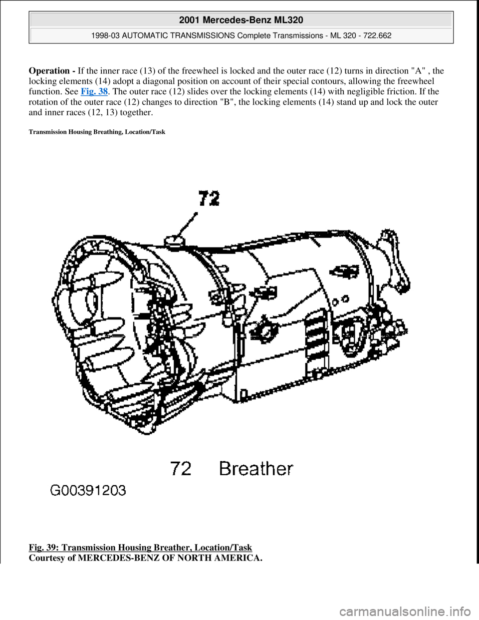
Transmission Housing Breathing, Location/Task
Fig. 39: Transmission Housing Breather, Location/Task
Courtesy of MERCEDES-BENZ OF NORTH AMERICA.
2001 Mercedes-Benz ML320
1998-03 AUTOMATIC TRANSMISSIONS Complete Transmissions - ML 320 - 722.662
me
Saturday, October 02, 2010 3:15:26 PMPage 77 © 2006 Mitchell Repair Information Company, LLC.
Page 1335 of 4133
Courtesy of MERCEDES-BENZ OF NORTH AMERICA.
Task - The ETC control module (N15/3) determines the instantaneous operating condition for the vehicle and
controls all gearshift sequences taking into account the ease of shifting and the driving situation. See Fig. 97
.
This involves receiving , converting and transmitting various digital and analog signals.
Input signals:
Starter Lock-Out Contact (Y3/6S1)
RPM Sensor 2 (Y3/6N2)
RPM Sensor 3 (Y3/6N3)
Transmission Oil Temperature Sensor (Y3/6B1)
Kickdown Switch (S16/6)
Gear Recognition Switch (S16/10)
Output signals:
Reverse/parking lock valve
Input and output signals:
Datalink connector (X11/4)
In addition there is a connection via the engine compartment bus to the:
ME-SFI Control Module (N3/10) or CDI Control Module (N3/9)
Traction System Control Module (N47)
Transfer Case Control Module (N78)
The solenoid valves for the modulating and shift pressure and for the gear changes are actuated by the ETC
control module (N15/3). The pressure required is calculated from all input signals, adjusted to the torque to be
transferred.
The following information from other systems is then processed:
ME-SFI Control Module (N3/10) or CDI Control Module (N3/9)
(Y66/1)
Selector lever position P/N to the engine control module (ME-SFI) (N3/10) (only on detection of the
selector lever position "P" or "N" on the transmission range recognition switch (S16/10) and at the starter
interlock contact (Y3/6s1)).
Traction system control module (N47):
Wheel speeds
2001 Mercedes-Benz ML320
1998-03 AUTOMATIC TRANSMISSIONS Complete Transmissions - ML 320 - 722.662
me
Saturday, October 02, 2010 3:15:27 PMPage 166 © 2006 Mitchell Repair Information Company, LLC.
Page 1393 of 4133
Location/Task/Design/Function Of Freewheel
See LOCATION/TASK/DESIGN/FUNCTION OF FREEWHEEL
.
Function Of Gear Shift (With Touch Shift)
Transmission with touch shift.
On transmission 722.6 the electrohydraulic control unit converts the electric signals going out from the
electronic transmission control (EGS) into hydraulic signals.
Faults occurring in the ETC control unit (N15/3) are handled by the limp-home system. The limp-home system
is designed so that the driver can reach a Service Operation even under extreme conditions.
Selector lever position "P", "R", "N" and "D" are transmitted by the electronic selector lever module control unit
(N15/5) on the Controller Area Network bus class C (engine compartment) (CAN-C) and in parallel to this by
means of a shift rod to the range selector lever at the transmission end. By touching or holding the selector lever
towards "+" or "-" the shift range is pre-selected and displayed in the instrument cluster (A1) until an upshift of
transmission 722.6 is possible.
Function Of Gear Change
See FUNCTION OF GEAR CHANGE
.
Emergency Default Mode, Function
See LIMP
-HOME MODE, FUNCTION.
Function Of Manual Drive Mode Selection
Oil Level Control, Function
See OIL LEVEL CONTROL, FUNCTION
.
Torque Converter Lockup Clutch Control, Function
See FUNCTION OF TORQUE CONVERTER LOCKUP CLUTCH CONTROL
.
Function Of Gear Shift (Without Touch Shift)
On transmission 722.6 the electrohydraulic control unit converts the electric signals going out from the
electronic transmission control (EGS) into hydraulic signals.
Faults occurring in the ETC control unit (N15/3) are handled by the limp-home system. The limp-home system
is designed so that the driver can reach a Service Operation even under extreme conditions.
Selector lever position "P", "R", "N" and "D" are transmitted by the electronic selector lever module control unit
2001 Mercedes-Benz ML320
1998-03 AUTOMATIC TRANSMISSIONS Complete Transmissions - ML 320 - 722.662
me
Saturday, October 02, 2010 3:15:28 PMPage 224 © 2006 Mitchell Repair Information Company, LLC.
Page 1449 of 4133
The ETC control module (N15/3) determines the instantaneous operating condition of the vehicle and controls
all gearshift sequences taking into account the ease of shifting and the driving situation. See Fig. 158
. This
involves receiving , converting and transmitting various digital and analog signals.
Input Signals:
Starter Lock-Out Contact (Y3/6S1)
RPM Sensor 2 (Y3/6N2)
RPM Sensor 3 (Y3/6N3)
Transmission Oil Temperature Sensor (Y3/6B1)
Kickdown Switch (S16/6)
Gear Recognition Switch (S16/10)
Output signals:
Reverse/Parking Lock Valve
Input And Output Signals:
Datalink Connector (X11/4)
In addition there is a connection via the engine compartment bus to the:
ME-SFI Control Module (N3/10) or CDI Control Module (N3/9)
Traction System Control Module (N47)
Transfer Case Control Module (N78)
The solenoid valves for the modulating and shift pressure and for the gear changes are actuated by the ETC
control module (N15/3). The pressure required is calculated from all input signals, adjusted to the torque to be
transferred.
The following information from other systems is then processed:
ME-SFI Control Module (N3/10) or CDI Control Module (N3/9)
Reverse And Parking Lock Solenoids (Y66/1)
Selector Lever Position (P/N) to the Engine Control Module (ME-SFI) (N3/10) (only on detection of the
selector lever position "P" or "N" on the transmission range recognition switch (S16/10) and at the starter
interlock contact (Y3/6s1)).
Traction System Control Module (N47):
Wheel Speeds
Gear Shift
Traction Status
2001 Mercedes-Benz ML320
1998-03 AUTOMATIC TRANSMISSIONS Complete Transmissions - ML 320 - 722.662
me
Saturday, October 02, 2010 3:15:29 PMPage 280 © 2006 Mitchell Repair Information Company, LLC.
Page 1503 of 4133
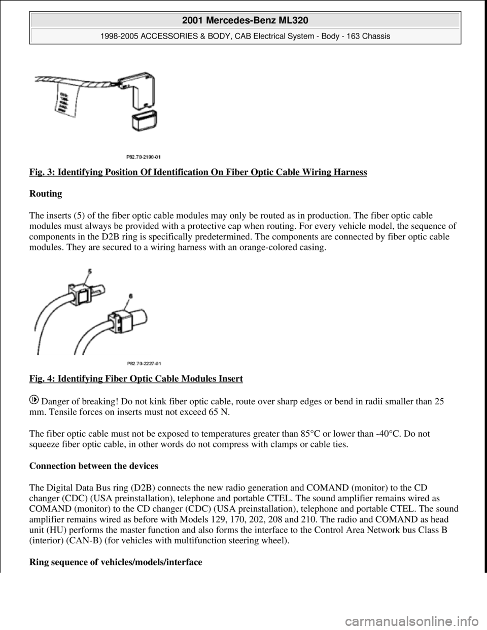
Fig. 3: Identifying Position Of Identification On Fiber Optic Cable Wiring Harness
Routing
The inserts (5) of the fiber optic cable modules may only be routed as in production. The fiber optic cable
modules must always be pr ovided with a protective cap when routing. For every vehicle model, the sequence of
components in the D2B ring is specifically predetermi ned. The components are connected by fiber optic cable
modules. They are secured to a wiring ha rness with an orange-colored casing.
Fig. 4: Identifying Fiber Optic Cable Modules Insert
Danger of breaking! Do not kink fiber optic cable, route over sharp edges or be nd in radii smaller than 25
mm. Tensile forces on inserts must not exceed 65 N.
The fiber optic cable must not be exposed to temperat ures greater than 85°C or lower than -40°C. Do not
squeeze fiber optic cable, in other words do not compress with clamps or cable ties.
Connection between the devices
The Digital Data Bus ring (D2B) connects the new ra dio generation and COMAND (monitor) to the CD
changer (CDC) (USA preinstallati on), telephone and portable CTEL. The sound amplifier remains wired as
COMAND (monitor) to the CD changer (CDC) (USA preinstallation), telephone and portable CTEL. The sound
amplifier remains wired as befo re with Models 129, 170, 202, 208 and 210. The radio and COMAND as head
unit (HU) performs the master function and also forms the interface to the Control Area Network bus Class B
(interior) (CAN-B) (for vehicles wi th multifunction steering wheel).
Ring sequence of vehi cles/models/interface
2001 Mercedes-Benz ML320
1998-2005 ACCESSORIES & BODY, CAB Electr ical System - Body - 163 Chassis
me
Saturday, October 02, 2010 3:30:04 PMPage 8 © 2006 Mitchell Repair Information Company, LLC.