Page 2244 of 4133
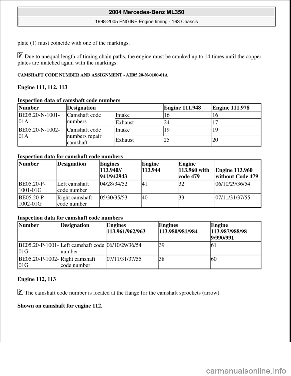
plate (1) must coincide with one of the markings. Due to unequal length of timing chai n paths, the engine must be cranked up to 14 times until the copper
plates are matched again with the markings.
CAMSHAFT CODE NUMBER AND ASSIGNMENT - AH05.20-N-0100-01A
Engine 111, 112, 113
Inspection data of camshaft code numbers
Inspection data for camshaft code numbers
Inspection data for camshaft code numbers
Engine 112, 113
The camshaft code number is located at the flange for the camshaft sprockets (arrow).
Shown on camshaft for engine 112.
NumberDesignationEngine 111.948Engine 111.978
BE05.20-N-1001-
01ACamshaft code
numbersIntake1616
Exhaust2417
BE05.20-N-1002-
01ACamshaft code
numbers repair
camshaftIntake1919
Exhaust2520
NumberDesignationEngines
113.940//
941/942943Engine
113.944Engine
113.960 with
code 479
Engine 113.960
without Code 479
BE05.20-P-
1001-01GLeft camshaft
code number04/28/34/52413206/10/29/36/54
BE05.20-P-
1002-01GRight camshaft
code number05/30/35/53403307/11/31/37/55
NumberDesignationEngines
113.961/962/963Engines
113.980/981/984Engine
113.987/988/98
9/990/991
BE05.20-P-1001-
01GLeft camshaft code
number06/10/29/36/543961
BE05.20-P-1002-
01GRight camshaft
code number07/11/31/37/553860
2004 Mercedes-Benz ML350
1998-2005 ENGINE Engine timing - 163 Chassis
me
Saturday, October 02, 2010 3:39:37 PMPage 3 © 2006 Mitchell Repair Information Company, LLC.
Page 2328 of 4133
DriftFig. 78
6Remove cylinder head
(1) from assembly
board (2)
Risk of explosion
and poisoning caused
by the melting down
or improper handling
of sodium-filled
valves. Risk of injury
caused by skin contact
with sodium resulting
in heat or chemical
burns.Do not open sodium-filled valves.
Wear protective gloves and safety
glasses when handling damaged
valves.AS05.30-Z-0001-01A
7Remove valve (14) Installation: Check surface of
valve stems for roughness and
formation of ridging (visual
inspection or with a nail). Replace
valves (14) with a rough stem
surface or formation of burrs. Grind
new or reused valves (14) with valve
grinding compound before
installation.
Disposal of sodium-
filled valvesExhaust valves with sodium fillingOS05.30-P-0001-01A
Checking
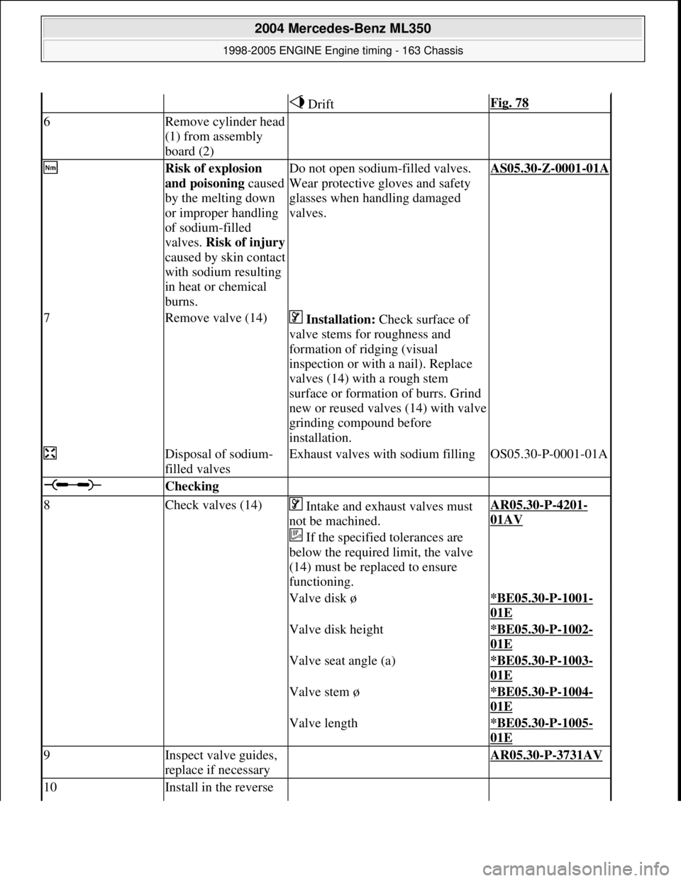
8Check valves (14) Intake and exhaust valves must
not be machined.
If the specified tolerances are
below the required limit, the valve
(14) must be replaced to ensure
functioning.AR05.30-P-4201-
01AV
Valve disk ø*BE05.30-P-1001-
01E
Valve disk height*BE05.30-P-1002-
01E
Valve seat angle (a)*BE05.30-P-1003-
01E
Valve stem ø*BE05.30-P-1004-
01E
Valve length*BE05.30-P-1005-
01E
9Inspect valve guides,
replace if necessary AR05.30-P-3731AV
10Install in the reverse
2004 Mercedes-Benz ML350
1998-2005 ENGINE Engine timing - 163 Chassis
me
Saturday, October 02, 2010 3:39:38 PMPage 87 © 2006 Mitchell Repair Information Company, LLC.
Page 2329 of 4133
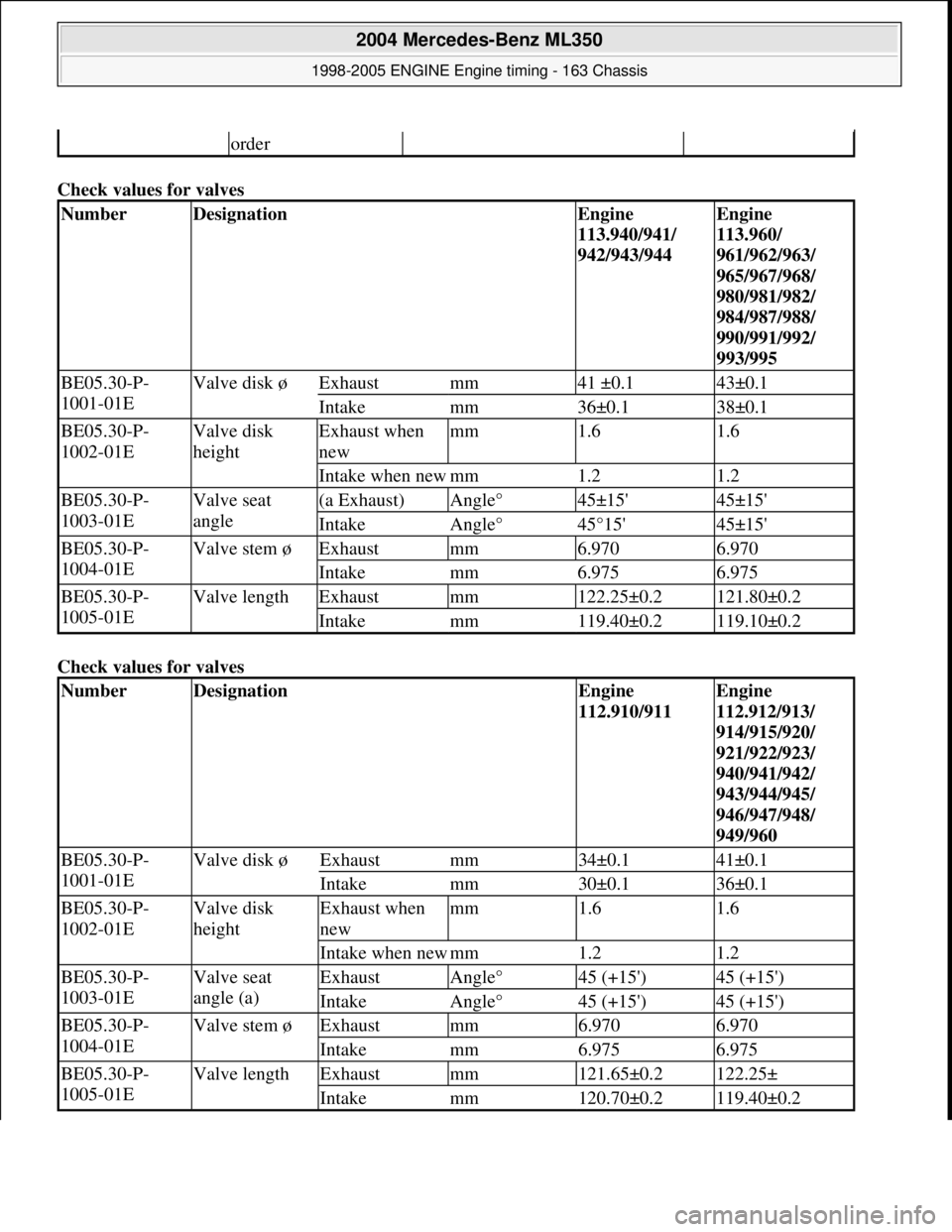
Check values for valves
Check values for valves
order
NumberDesignationEngine
113.940/941/
942/943/944Engine
113.960/
961/962/963/
965/967/968/
980/981/982/
984/987/988/
990/991/992/
993/995
BE05.30-P-
1001-01EValve disk øExhaustmm41 ±0.143±0.1
Intakemm36±0.138±0.1
BE05.30-P-
1002-01EValve disk
heightExhaust when
newmm1.61.6
Intake when newmm1.21.2
BE05.30-P-
1003-01EValve seat
angle(a Exhaust)Angle°45±15'45±15'
IntakeAngle°45°15'45±15'
BE05.30-P-
1004-01EValve stem øExhaustmm6.9706.970
Intakemm6.9756.975
BE05.30-P-
1005-01EValve lengthExhaustmm122.25±0.2121.80±0.2
Intakemm119.40±0.2119.10±0.2
NumberDesignationEngine
112.910/911Engine
112.912/913/
914/915/920/
921/922/923/
940/941/942/
943/944/945/
946/947/948/
949/960
BE05.30-P-
1001-01EValve disk øExhaustmm34±0.141±0.1
Intakemm30±0.136±0.1
BE05.30-P-
1002-01EValve disk
heightExhaust when
newmm1.61.6
Intake when newmm1.21.2
BE05.30-P-
1003-01EValve seat
angle (a)ExhaustAngle°45 (+15')45 (+15')
IntakeAngle°45 (+15')45 (+15')
BE05.30-P-
1004-01EValve stem øExhaustmm6.9706.970
Intakemm6.9756.975
BE05.30-P-
1005-01EValve lengthExhaustmm121.65±0.2122.25±
Intakemm120.70±0.2119.40±0.2
2004 Mercedes-Benz ML350
1998-2005 ENGINE Engine timing - 163 Chassis
me
Saturday, October 02, 2010 3:39:38 PMPage 88 © 2006 Mitchell Repair Information Company, LLC.
Page 2333 of 4133
945/946/948/
960/961/962/
963/964/965/
966/967/968/
969/971/980/
981/982/984/
986/987/988/
990/991/992/
993/995
BE05.30-P-
1001-02DOutside
diameter of
exhaust and
intake valve
guideStandard
seriesmm12.540...12.55112.540...12.551
Standard I
series
(color:
blue)mm12.560...12.57112.560...12.571
Repair
stage I
(color: red)mm12.740...12.75112.740...12.751
Repair
stage II
(color:
yellow)mm13.140...13.15113.140...13.151
BE05.30-P-
1002-02DBore
diameter in
cylinder
head of
exhaust and
intake valve
guideStandard
seriesmm12.500...12.51112.500...12.511
Standard I
series
(color:
blue)mm12.520...12.53112.520...12.531
Repair
stage I
(color: red)mm12.700...12.71112.700...12.711
Repair
stage II
(color:
yellow)mm13.100...13.11113.100...13.113.100...13.11113.100...13.1
BE05.30-P-
1003-02DOverlap in cylinder headmm0.029...0.0510.029...0.051
BE05.30-P-
1004-02DLengthLmm5050
BE05.30-P-
1005-02DDimensionAmm14.3 (±0.2)14.3 (±0.2)
2004 Mercedes-Benz ML350
1998-2005 ENGINE Engine timing - 163 Chassis
me
Saturday, October 02, 2010 3:39:38 PMPage 92 © 2006 Mitchell Repair Information Company, LLC.
Page 2336 of 4133
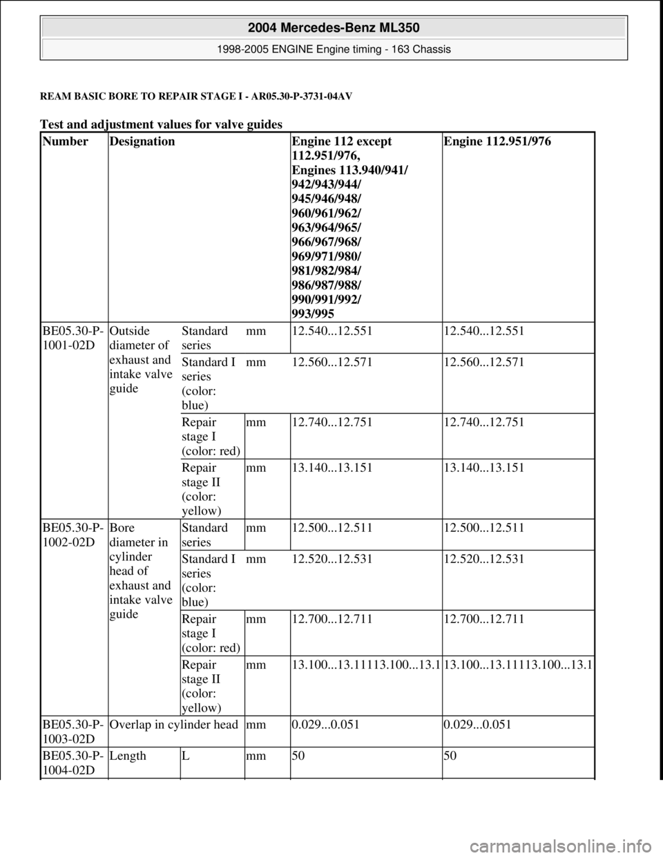
REAM BASIC BORE TO REPAIR STAGE I - AR05.30-P-3731-04AV
Test and adjustment values for valve guides
NumberDesignationEngine 112 except
112.951/976,
Engines 113.940/941/
942/943/944/
945/946/948/
960/961/962/
963/964/965/
966/967/968/
969/971/980/
981/982/984/
986/987/988/
990/991/992/
993/995Engine 112.951/976
BE05.30-P-
1001-02DOutside
diameter of
exhaust and
intake valve
guideStandard
seriesmm12.540...12.55112.540...12.551
Standard I
series
(color:
blue)mm12.560...12.57112.560...12.571
Repair
stage I
(color: red)mm12.740...12.75112.740...12.751
Repair
stage II
(color:
yellow)mm13.140...13.15113.140...13.151
BE05.30-P-
1002-02DBore
diameter in
cylinder
head of
exhaust and
intake valve
guideStandard
seriesmm12.500...12.51112.500...12.511
Standard I
series
(color:
blue)mm12.520...12.53112.520...12.531
Repair
stage I
(color: red)mm12.700...12.71112.700...12.711
Repair
stage II
(color:
yellow)mm13.100...13.11113.100...13.113.100...13.11113.100...13.1
BE05.30-P-
1003-02DOverlap in cylinder headmm0.029...0.0510.029...0.051
BE05.30-P-
1004-02DLengthLmm5050
2004 Mercedes-Benz ML350
1998-2005 ENGINE Engine timing - 163 Chassis
me
Saturday, October 02, 2010 3:39:38 PMPage 95 © 2006 Mitchell Repair Information Company, LLC.
Page 2339 of 4133
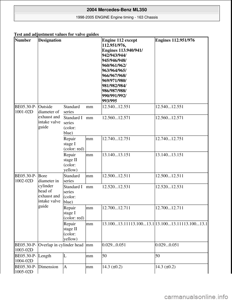
Test and adjustment values for valve guides
NumberDesignationEngine 112 except
112.951/976,
Engines 113.940/941/
942/943/944/
945/946/948/
960/961/962/
963/964/965/
966/967/968/
969/971/980/
981/982/984/
986/987/988/
990/991/992/
993/995Engines 112.951/976
BE05.30-P-
1001-02DOutside
diameter of
exhaust and
intake valve
guideStandard
seriesmm12.540...12.55112.540...12.551
Standard I
series
(color:
blue)mm12.560...12.57112.560...12.571
Repair
stage I
(color: red)mm12.740...12.75112.740...12.751
Repair
stage II
(color:
yellow)mm13.140...13.15113.140...13.151
BE05.30-P-
1002-02DBore
diameter in
cylinder
head of
exhaust and
intake valve
guideStandard
seriesmm12.500...12.51112.500...12.511
Standard I
series
(color:
blue)mm12.520...12.53112.520...12.531
Repair
stage I
(color: red)mm12.700...12.71112.700...12.711
Repair
stage II
(color:
yellow)mm13.100...13.11113.100...13.113.100...13.11113.100...13.1
BE05.30-P-
1003-02DOverlap in cylinder headmm0.029...0.0510.029...0.051
BE05.30-P-
1004-02DLengthLmm5050
BE05.30-P-
1005-02DDimensionAmm14.3 (±0.2)14.3 (±0.2)
2004 Mercedes-Benz ML350
1998-2005 ENGINE Engine timing - 163 Chassis
me
Saturday, October 02, 2010 3:39:38 PMPage 98 © 2006 Mitchell Repair Information Company, LLC.
Page 2340 of 4133
Fig. 114: Identifying Feeler (102 589 01 23 00)
1. Clean bore of valve guide (1) (never use a hard object).
2. Inspect surface of bore for scores or signs of rubbi ng. If damage to the surface is present, the valve
guide must be replaced and the valve stem inspected for uneven areas. If the stem is damaged, the valve
must be replaced together with the valve guide.
Fig. 115: Identifying Valve Guide
3. If it is possible to inse rt the side of the hole gauge (3) marked with "+220" over its full length (5 mm)
into the valve guide, it is then necessary to repl ace the valve guide. Inspect bore of valve guide in
longitudinal and tran sverse direction.
Fig. 116: Inserting Side Of Hole Gauge
CHECK, REMOVE, INSTALL VA LVE GUIDES - AR05.30-P-3731AV
2004 Mercedes-Benz ML350
1998-2005 ENGINE Engine timing - 163 Chassis
me
Saturday, October 02, 2010 3:39:38 PMPage 99 © 2006 Mitchell Repair Information Company, LLC.
Page 2341 of 4133
ENGINE 112
ENGINE 112.945 in MODEL 463.209 /232 /233 /244 /245 /250
ENGINE 113.962 in MODEL 463.206 /240 /241 /247 /248 /249 /254
ENGINE 113.982 in MODEL 463.243/246
ENGINE 113 in MODEL 129, 163, 202, 203, 208, 209, 210, 211, 215, 220, 230
Fig. 117: Identifying Valve Guides
Remove/install
1Remove valves
Engine 113 except
113.995AR05.30-P-3511AV
Engine 113.995AR05.30-P-3511RVK
2Inspect valve guides (1, 2) AR05.30-P-3731-06AV
Installation depth of valve
guide*BE05.30-P-1005-02D
3Knock out valve guides (1,
2) The valve guides on
the exhaust and intake
sides are identical.AR05.30-P-3731-01AV
Overall length of valve *BE05.30-P-1004-02D
2004 Mercedes-Benz ML350
1998-2005 ENGINE Engine timing - 163 Chassis
me
Saturday, October 02, 2010 3:39:38 PMPage 100 © 2006 Mitchell Repair Information Company, LLC.