1997 MERCEDES-BENZ ML430 length
[x] Cancel search: lengthPage 1140 of 4133

336 IndexSide windows 144
Automatic closing 145
Automatic opening 145
Cleaning 237
Closing 145
Closing fully (Express-close) 145
Opening 145
Opening and closing 144
Opening fully (Express-open) 145
Rear quarter window 146
Stopping 145
Synchronizing power windows 146
Simultaneous wiping and washing
Rear window wiper/washer 51
Windshield wipers 50
Single wipe 50
Sliding/pop-up roof* 148
Closing 148, 265
Opening 148, 265
Synchronizing 149
Snow chains 231
Spare fuses 287
Spare parts service 290Spare wheel 259
Mounting 274
Removing 259
Speed
Saving current 151
Speed settings
Cruise control 152
Speedometer 25
Speedometer display
Additional indicators 256
Split rear bench seat 99
SRS 66, 314
Indicator lamp 255
Standing lamps 107
Replacing bulbs 266, 267
Standing water
Driving instructions 200
StArt
Display messages 256
Starting difficulties 47
Starting position 33
Starting the engine 46Steep terrain
Driving 202
Steering column
Height adjustment 39
Length adjustment 39
Steering lock 23, 33
Positions 33
Steering wheel
Adjusting 39
Adjustment 39
Cleaning 238
Stolen vehicle
Tracking services 180
Stop watch 189
Stopping
Windows 145
Storage compartments
Glove box 164
Under front passenger seat* 164
Storing (Memory function*)
Positions into memory 106
Stranded vehicle 286
Page 1154 of 4133
closed. The intake air must flow through the whole intake pipe. Its length is selected in such a way that the
pressure waves, produced by the inducting pistons, arrive at the right moment at the open intake valves for the
next induction stroke. The result is improved cylinder charge and thus an increase in torque.
At higher engine speeds (e.g. from 3900 rpm) the actuation to the variable intake manifold switchover valve is
interrupted - the variable flaps open as a result of the spring force. Through the shortened route the pressure
waves arrive in time even at higher rotational speeds before the closing of the intake valves to the combustion
chamber.
INTAKE MANIFOLD, DESIGN - GF09.20-P-3102-03A
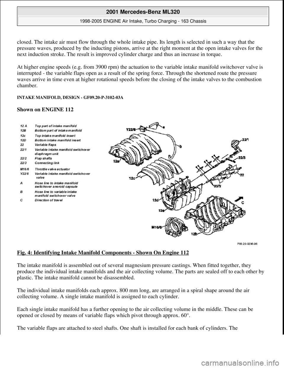
Shown on ENGINE 112
Fig. 4: Identifying Intake Manifold Components
- Shown On Engine 112
The intake manifold is assembled out of several magnesium pressure castings. When fitted together, they
produce the individual intake manifolds and the air collecting volume. The parts are sealed off to each other by
plastic. The intake manifold cannot be disassembled.
The individual intake manifolds each approx. 800 mm long, are arranged in a spiral shape around the air
collecting volume. A single intake manifold is assigned to each cylinder.
Each single intake manifold has a further opening to the air collecting volume in the middle. These can be
opened or closed by means of variable flaps which pivot through approx. 60°.
The variable flaps are attached to steel shafts. One shaft is installed for each bank of c
ylinders. The
2001 Mercedes-Benz ML320
1998-2005 ENGINE Air Intake, Turbo Charging - 163 Chassis
me
Saturday, October 02, 2010 3:16:57 PMPage 3 © 2006 Mitchell Repair Information Company, LLC.
Page 1155 of 4133
interconnected flap shafts are closed by means of vacuum by the intake manifold switchover diaphragm unit.
When the variable intake manifold switchover valve is open, the vacuum is supplied from a vacuum reservoir
with check valve in the intake manifold. The reservoir volume is designed for about 5 operations without
renewed evacuation.
The variable flaps open by means of spring force.
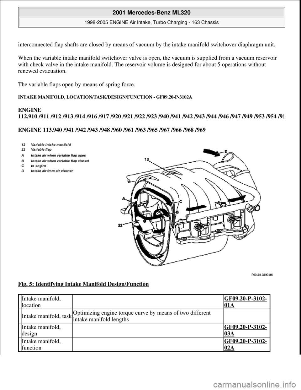
INTAKE MANIFOLD, LOCATION/TASK/DESIGN/FUNCTION - GF09.20-P-3102A
ENGINE
112.910 /911 /912 /913 /914 /916 /917 /920 /921 /922 /923 /940 /941 /942 /943 /944 /946 /947 /949 /953 /954 /9
5
ENGINE 113.940 /941 /942 /943 /948 /960 /961 /963 /965 /967 /966 /968 /969
Fig. 5: Identifying Intake Manifold Design/Function
Intake manifold,
location GF09.20-P-3102-
01A
Intake manifold, taskOptimizing engine torque curve by means of two different
intake manifold lengths
Intake manifold,
design GF09.20-P-3102-
03A
Intake manifold,
function GF09.20-P-3102-
02A
2001 Mercedes-Benz ML320
1998-2005 ENGINE Air Intake, Turbo Charging - 163 Chassis
me
Saturday, October 02, 2010 3:16:57 PMPage 4 © 2006 Mitchell Repair Information Company, LLC.
Page 1502 of 4133
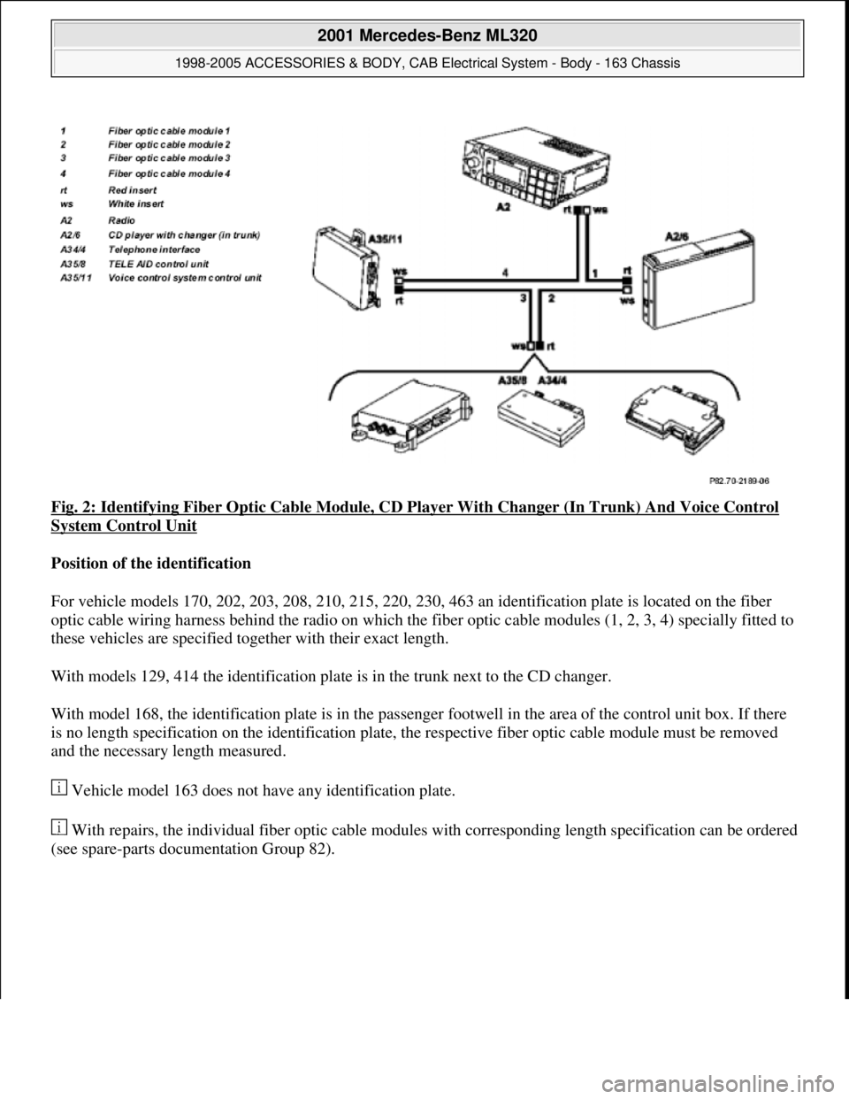
Fig. 2: Identifying Fiber Optic Cable Module, CD Player With Changer (In Trunk) And Voice Control
System Control Unit
Position of the identification
For vehicle models 170, 202, 203, 208, 210, 215, 220, 230, 463 an identification plate is located on the fiber
optic cable wiring harness behind the radio on which the fiber optic cable modules (1, 2, 3, 4) specially fitted to
these vehicles are specified together with their exact length.
With models 129, 414 the identification plate is in the trunk next to the CD changer.
With model 168, the identification plate is in the passenger footwell in the area of the control unit box. If there
is no length specification on the identification plate, the respective fiber optic cable module must be removed
and the necessary length measured.
Vehicle model 163 does not have any identification plate.
With repairs, the individual fiber optic cable modules with corresponding length specification can be ordered
(see spare-parts documentation Group 82).
2001 Mercedes-Benz ML320
1998-2005 ACCESSORIES & BODY, CAB Electrical System - Body - 163 Chassis
me
Saturday, October 02, 2010 3:30:04 PMPage 7 © 2006 Mitchell Repair Information Company, LLC.
Page 1509 of 4133
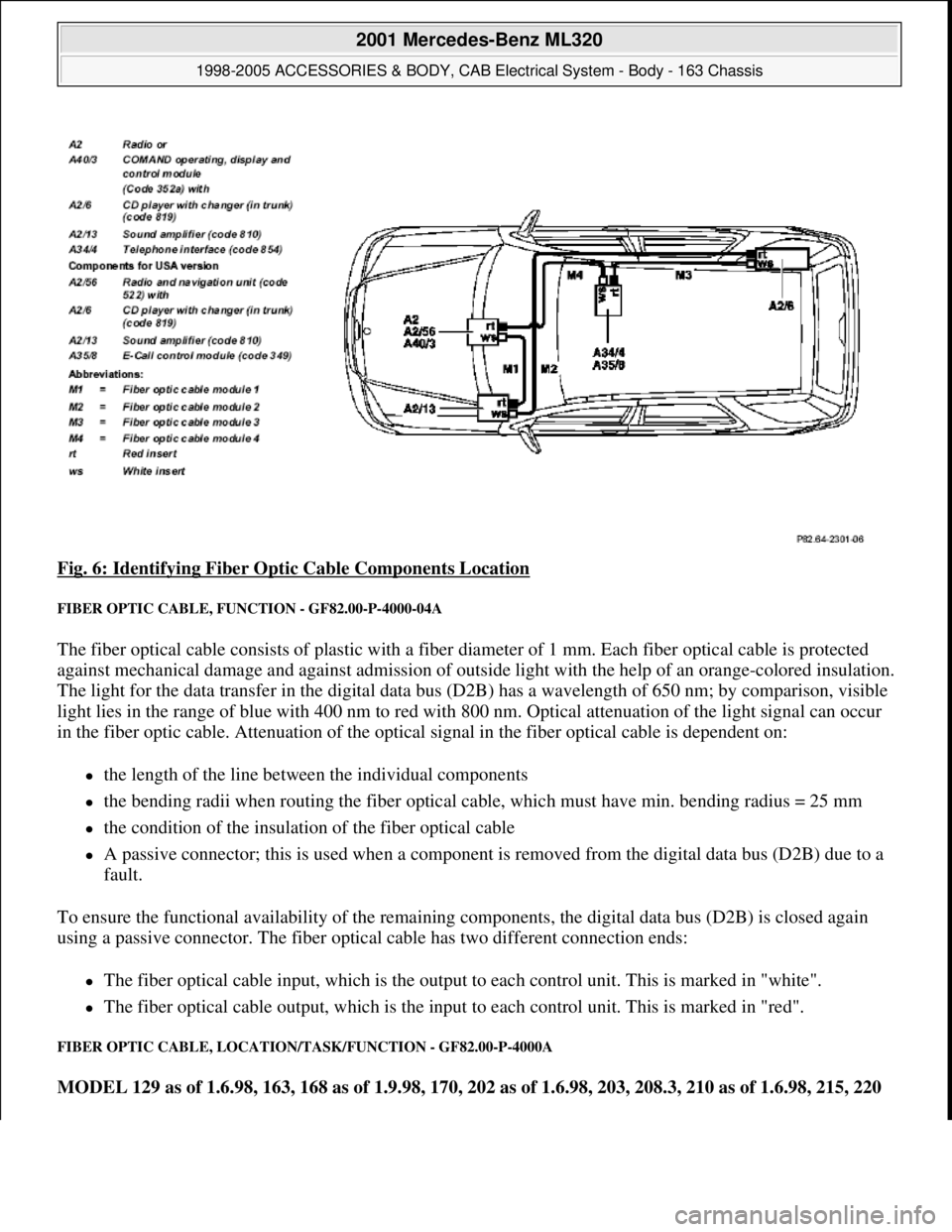
Fig. 6: Identifying Fiber Optic Cable Components Location
FIBER OPTIC CABLE, FUNCTION - GF82.00-P-4000-04A
The fiber optical cable consists of plastic with a fiber diameter of 1 mm. Each fiber optical cable is protected
against mechanical damage and against admission of outside light with the help of an orange-colored insulation.
The light for the data transfer in the digital data bus (D2B) has a wavelength of 650 nm; by comparison, visible
light lies in the range of blue with 400 nm to red with 800 nm. Optical attenuation of the light signal can occur
in the fiber optic cable. Attenuation of the optical signal in the fiber optical cable is dependent on:
the length of the line between the individual components
the bending radii when routing the fiber optical cable, which must have min. bending radius = 25 mm
the condition of the insulation of the fiber optical cable
A passive connector; this is used when a component is removed from the digital data bus (D2B) due to a
fault.
To ensure the functional availability of the remaining components, the digital data bus (D2B) is closed again
using a passive connector. The fiber optical cable has two different connection ends:
The fiber optical cable input, which is the output to each control unit. This is marked in "white".
The fiber optical cable output, which is the input to each control unit. This is marked in "red".
FIBER OPTIC CABLE, LOCATION/TASK/FUNCTION - GF82.00-P-4000A
MODEL 129 as of 1.6.98, 163, 168 as of 1.9.98, 170, 202 as of 1.6.98, 203, 208.3, 210 as of 1.6.98, 215, 220
2001 Mercedes-Benz ML320
1998-2005 ACCESSORIES & BODY, CAB Electrical System - Body - 163 Chassis
me
Saturday, October 02, 2010 3:30:04 PMPage 14 © 2006 Mitchell Repair Information Company, LLC.
Page 1584 of 4133
FERRY
TOLL
After calculation of the route, the navigation processor makes up a list of the streets along the route. This route
list is used for navigation. It can be displayed during navigation by pressing the "I" (INFO) and "RTE" (Route)
buttons.
Route updating
If the driver deviates from the calculated route, a new route list is automatically calculated by the navigation
processor. The current position and the direction of travel are taken into consideration, and the new route is
optimized accordingly. This is accomplished without any message on the display.
Circumventing traffic jams with "Traffic jam" menu key function
After a traffic jam is reported on traffic radio and before reaching the affected section, a route can be calculated
for driving around the traffic jam. For this purpose, activate the "Traffic jam" menu and enter the length of the
traffic jam including the distance to the start of the traffic jam.
The "Traffic jam" function is also available for Federal and State highways as well as for inner city areas.
Trips outside the digitized map area
If the vehicle leaves the digitized DVD map area (e.g. driving into a multi-level car park), then no route can be
calculated or updated. "OFF ROAD" appears on the display. Upon leaving the map boundary, the display "OFF
MAP" appears.
Destinations which lie outside of the digitalized map area cannot be taken into consideration on calculation of
the route.
ROUTE CALCULATION, FUNCTION - GF82.61-P-3011GI
MODEL 163 as of 1.9.01 with CODE (522) Modular control system (MCS) radio USA with CODE (357)
Navigation system - additional unit with CODE (818b) Single CD player - additional unit with CODE
(491) U.S. version
The route is calculated and updated continuously by the navigation processor after entering the destination on
the radio and navigation module (A2/56) It can only be calculated within the digitized map area. The
calculated route is the prerequisite of the guidance system .
Route calculation
The navigation processor calculates the route with the aid of the CD-ROMmap data, the entered destination
Destination guidance,
function GF82.61-P-3012D
2001 Mercedes-Benz ML320
1998-2005 ACCESSORIES & BODY, CAB Electrical System - Body - 163 Chassis
me
Saturday, October 02, 2010 3:30:05 PMPage 89 © 2006 Mitchell Repair Information Company, LLC.
Page 1588 of 4133
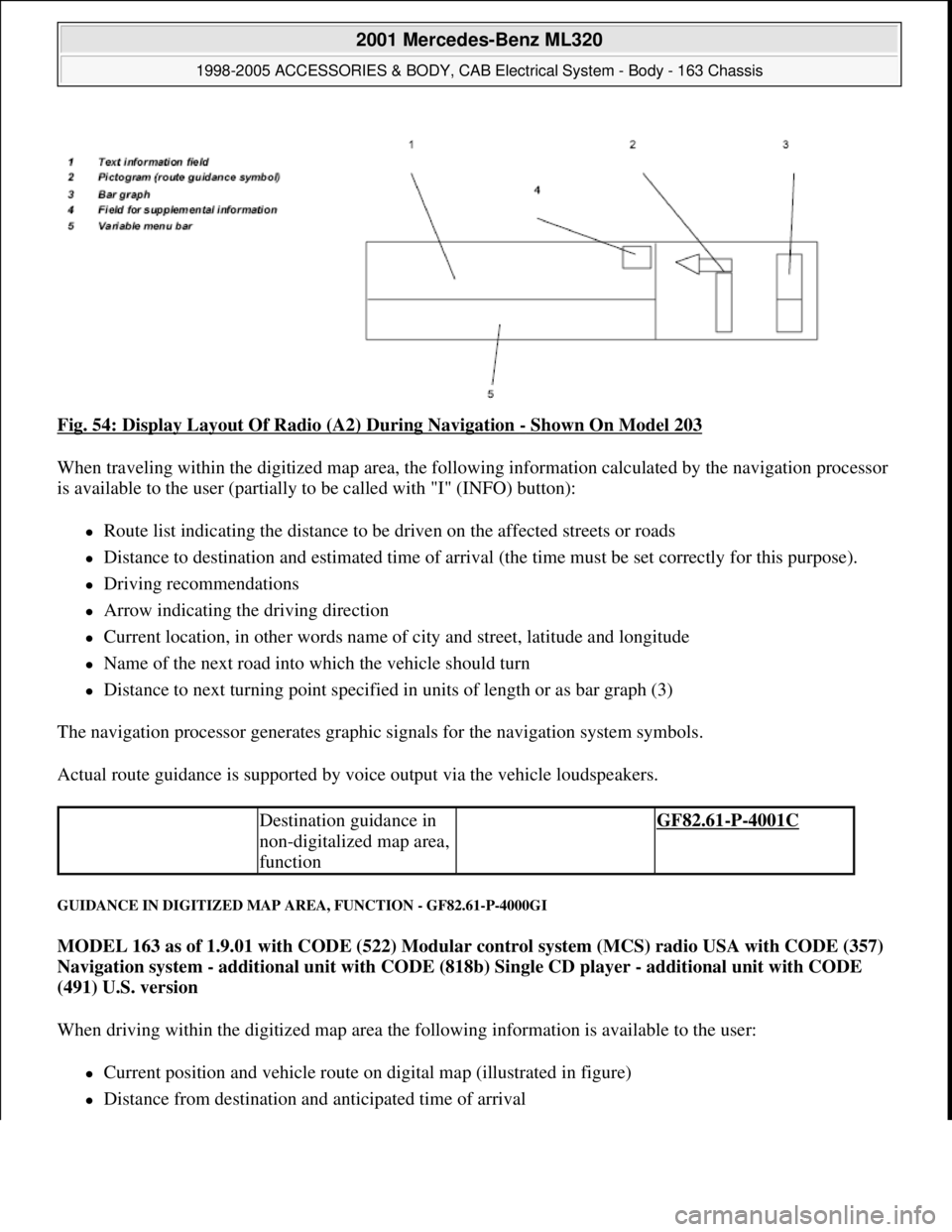
Fig. 54: Display Layout Of Radio (A2) During Navigation - Shown On Model 203
When traveling within the digitized map area, the following information calculated by the navigation processor
is available to the user (partially to be called with "I" (INFO) button):
Route list indicating the distance to be driven on the affected streets or roads
Distance to destination and estimated time of arrival (the time must be set correctly for this purpose).
Driving recommendations
Arrow indicating the driving direction
Current location, in other words name of city and street, latitude and longitude
Name of the next road into which the vehicle should turn
Distance to next turning point specified in units of length or as bar graph (3)
The navigation processor generates graphic signals for the navigation system symbols.
Actual route guidance is supported by voice output via the vehicle loudspeakers.
GUIDANCE IN DIGITIZED MAP AREA, FUNCTION - GF82.61-P-4000GI
MODEL 163 as of 1.9.01 with CODE (522) Modular control system (MCS) radio USA with CODE (357)
Navigation system - additional unit with CODE (818b) Single CD player - additional unit with CODE
(491) U.S. version
When driving within the digitized map area the following information is available to the user:
Current position and vehicle route on digital map (illustrated in figure)
Distance from destination and anticipated time of arrival
Destination guidance in
non-digitalized map area,
function GF82.61-P-4001C
2001 Mercedes-Benz ML320
1998-2005 ACCESSORIES & BODY, CAB Electrical System - Body - 163 Chassis
me
Saturday, October 02, 2010 3:30:05 PMPage 93 © 2006 Mitchell Repair Information Company, LLC.
Page 1589 of 4133
Driving direction recommendation
Distance to next turning point (specified in units of length)
The data is determined by the navigation processor and transmitted to the radio and navigation module
(A2/56) The current route guidance is primarily supported by the voice output (English).
The scale of the displayed map can be changed in increments. In addition it is possible to select whether the
map is aligned in the direction of motion Head-Up ) or toward the north North-Up ). The graphical signals for
map illustration is generated by the navigation processor.
DESTINATION GUIDANCE IN NON-DIGITALIZED MAP AREA, FUNCTION - GF82.61-P-4001C
MODEL 163, 168, 170, 203.0 /2 /7, 208, 209.3 /4, 210 with CODE (353) Audio 30 APS
When traveling outside of the digitized map area (e.g. company grounds, parking buildings, dirt roads,...),
however still within the DVD map boundaries, the navigation processor switches over to "navigation system in
non-digitized map area".
On the radio (A2) display the following message appears:
"OFF ROAD"
If the vehicle is also outside the DVD map limit, the following message appears:
"OFF MAP"
In both cases, only basic location finding is accomplished with correction using the GPS data.
A (limited) route guidance can be conducted only with specification of the:
Distance from the destination as the crow flies
Direction to the destination (as an arrow)
After reentering the digitized map area, the system automatically continues with "navigation system in digitized
map area". The possible streets/roads on which the vehicle may be located are determined with the aid of GPS
location finding. During this process a slight delay in the route guidance may result.
The road data of several Central European countries are stored on the navigation DVD, so that the "OFF
MAP" message will not appear, if borders between the stored countries are crossed. No special foreign country
DVD has to be inserted.
Voice output, function GF82.85-P-3001GI
Guidance in non-digitized
map area, function GF82.61-P-4001GI
2001 Mercedes-Benz ML320
1998-2005 ACCESSORIES & BODY, CAB Electrical System - Body - 163 Chassis
me
Saturday, October 02, 2010 3:30:05 PMPage 94 © 2006 Mitchell Repair Information Company, LLC.