1997 MERCEDES-BENZ ML430 wiring
[x] Cancel search: wiringPage 3476 of 4133
side
4
Disconnect blue connector
(ML/B) from bottom of fuse
holder
5Remove lamp unit AR82.10-P-
4730GH
6
Remove original additional
fan connector (M4x1) from
additional fan and fasten to
present wiring harness (5)
with adhesive tape on clip
(6)
Install
7
Route new additional fan
connector (3) on auxiliary
wiring harness (2) to
additional fan connector and
insert
Route along original wiring harness at rear of
installation opening of lamp unit
8
Fasten auxiliary wiring
harness (2) to original wiring
harness in area of clips with
cable straps.
9
Fasten auxiliary wiring
harness ground cable (1) to
left front ground (W9)
*BA54.10-
P-1017-01C
10
Route auxiliary wiring
harness (2) into fuse and
relay module
Route fuse and relay module along wiring harness
for fuse and relay module (4) below installation
opening of lamp unit between washer water reservoir
and fender to grommet on left side of fuse and relay
module. Remove adhesive tape from rubber
grommet, thread wiring harness through and reinstall
adhesive tape.
11
Route connection terminal
of auxiliary wiring harness
(2) to blue connector
(ML/B) at bottom of fuse
holder
12
Open housing of connector
(ML/B) and remove lead
from plug location 1
13
Separate present lead
approx. 100 mm in front
connection terminal
Insert connection terminal
for auxiliary wiring harness
Ensure that connection terminal arrests correctly
2001 Mercedes-Benz ML320
1998-2005 HVAC Climate Control - 163 Chassis
me
Saturday, October 02, 2010 3:23:19 PMPage 232 © 2006 Mitchell Repair Information Company, LLC.
Page 3477 of 4133
Battery
Parts ordering notes
14
(2) into plug location 1 of
connector (ML/B) and close
connector housing.in connector.
15
Insert blue connector
(ML/B) at bottom of fuse
holder and fasten auxiliary
wiring harness (2) to
separated lead with adhesive
tape
Ensure that stripped wire ends are insulated with
adhesive tape.
16
Fasten fuse holder to fuse
and relay module with
screws
17Insert new 40 A fuse at
position f44 in fuse holder The larger line diameter of the auxiliary wiring
harness (2) allows installation of a 40 A fuse.
18Install in the reverse order
19Check function of additional
fan
NumberDesignationModel 163
BA54.10-P-1017-01CNut, ground cable to bodyNm18
Part no.DesignationQuantity
163 540 00 35Auxiliary wiring harness1
910153 000000Fuse, 40 A1
2001 Mercedes-Benz ML320
1998-2005 HVAC Climate Control - 163 Chassis
me
Saturday, October 02, 2010 3:23:19 PMPage 233 © 2006 Mitchell Repair Information Company, LLC.
Page 3494 of 4133
4
Remove side covers (12)
Danger of breaking retaining lugs. Do not
damage instrument panel.
Up to VIN A145272, X708318:
3 covers:
Remove side covers first. Detach center
cover from instrument panel and rotate so
that the retaining lugs point upwards. Then
pull out to the right.
As of VIN A145273, X708319:
2 covers: First
remove the right cover, then the left. It is not
necessary to detach the connectors. The
covers can remain attached to the wiring
harness.
Long wedge
*115589035900
5
Remove frame (5) of instrument cluster
Lift clips carefully, risk of fracture.
Push the clips (4) outwards (arrow
direction A) and ease the frame down towards
the footwell (arrow direction B) until the top of
the frame disengages.
Installation:
Insert the hooks (6) of the
frame into the bracket (13) and push the
frame upwards until the clips snap into place.
Installation:
Insert the lugs (7) on the
frame into the receptacles (8) on the
instrument cluster.
6
Unscrew screws (9)
7
Remove expanding clips (10)
8
Pull instrument cluster (A1) forwards
9
Unlock, open and pull off connector (11)
10
Remove instrument cluster
Make sure the steering wheel is not
scratched.
Tilt the upper edge of the instrument
cluster towards the steering wheel and move
to the right out of the instrument panel.
11
Install in the reverse order
12
Perform function check
a
Instrument cluster (IC) diagnosis operational
check
AD54.30-P-3000A
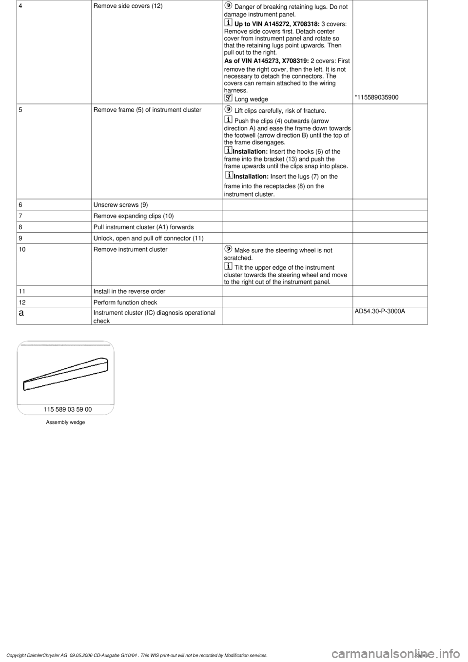
Assembly wedge
115 589 03 59 00
Copyright DaimlerChrysler AG 09.05.2006 CD-Ausgabe G/10/04 . This WIS print-out will not be recorde
d by Modification services.
Page 2
Page 3498 of 4133

AF54.30-P-8400A
Instrument cluster indicates: Oil sensor defective, oil level below min. or oil level
above max. with engine running and at operating temperature. No DTC stored.
19.5.98
MODEL
129.0, 163.1, 202.0, 208.3 /4, 210.0 /2 /6, 220.0 /1 with ENGINE 112
MODEL
129.0, 163.1, 202.0, 208.3 /4, 210.0 /2, 220.0 /1 with ENGINE 113
Damage code
Cause
Remedy
54 201 90
Oil low, connector defective or coding error
1
Shut off engine and wait 2 min. (key
position 0)
Instrument cluster indicates oil sensor
defective, oil level below min. or oil level
above max. with engine warm and running.
No DTC stored in DTC memory!
2
Check oil level with oil dipstick
3
Check oil level on instrument cluster:
- Key in steering wheel lock position 2,
engine not running
- Wait until - - - - - - appears on
instrument cluster
- When this is displayed press the reset
button for the tripodometer twice within
1 sec. (display appears only after
expiration of a waiting time (max. 30
min.) depending on engine oil
temperature)
Oil level is at bottom mark on oil dipstick
and instrument cluster indicates:
-1L
, -
1,5L
or -2L
#
4
Add quantity of oil indicated on
instrument cluster display and repeat
test.
Oil level at upper mark on dipstick and
instrument cluster indicates either oil level
okay or -1L
, -
1,5L
, -2L
#
5
Recode instrument cluster
AF54.30-P-8600A
Problem still present
#
6
Check cable to oil sensor, oil sensor
connectors, control module and fuse
box (see wiring diagram) for good contact
Copyright DaimlerChrysler AG 05.06.2006 CD-Ausgabe G/10/04 . This WIS print-out will not be recorde
d by Modification services.
Page 1
Page 3510 of 4133
AR68.10-P-1111GH
Remove/install instrument panel carrier
17.3.97
MODEL
163.113 /128 /136 /154 /157 /172 /174 /175
P68.10-0612-09
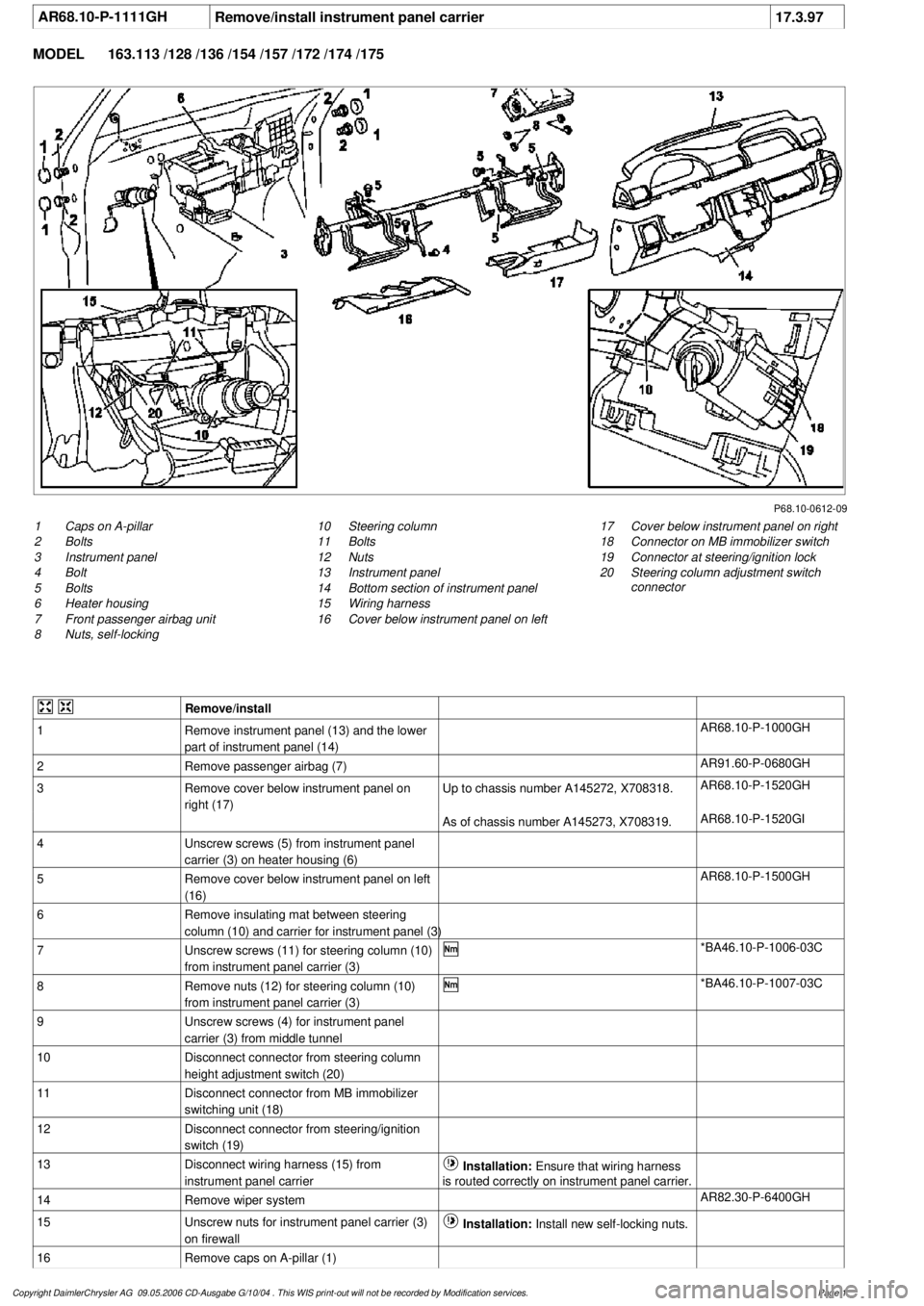
1
Caps on A-pillar
2
Bolts
3
Instrument panel
4
Bolt
5
Bolts
6
Heater housing
7
Front passenger airbag unit
8
Nuts, self-locking
17
Cover below instrument panel on right
18
Connector on MB immobilizer switch
19
Connector at steering/ignition lock
20
Steering column adjustment switch
connector
10
Steering column
11
Bolts
12
Nuts
13
Instrument panel
14
Bottom section of instrument panel
15
Wiring harness
16
Cover below instrument panel on left
Remove/install
1
Remove instrument panel (13) and the lower
part of instrument panel (14)
AR68.10-P-1000GH
2
Remove passenger airbag (7)
AR91.60-P-0680GH
3
Remove cover below instrument panel on
right (17)
Up to chassis number A145272, X708318.
AR68.10-P-1520GH
As of chassis number A145273, X708319.
AR68.10-P-1520GI
4
Unscrew screws (5) from instrument panel
carrier (3) on heater housing (6)
5
Remove cover below instrument panel on left
(16)
AR68.10-P-1500GH
6
Remove insulating mat between steering
column (10) and carrier for instrument panel (3)
7
Unscrew screws (11) for steering column (10)
from instrument panel carrier (3)
*BA46.10-P-1006-03C
8
Remove nuts (12) for steering column (10)
from instrument panel carrier (3)
*BA46.10-P-1007-03C
9
Unscrew screws (4) for instrument panel
carrier (3) from middle tunnel
10
Disconnect connector from steering column
height adjustment switch (20)
11
Disconnect connector from MB immobilizer
switching unit (18)
12
Disconnect connector from steering/ignition
switch (19)
13
Disconnect wiring harness (15) from
instrument panel carrier
Installation:
Ensure that wiring harness
is routed correctly on instrument panel carrier.
14
Remove wiper system
AR82.30-P-6400GH
15
Unscrew nuts for instrument panel carrier (3)
on firewall
Installation:
Install new self-locking nuts.
16
Remove caps on A-pillar (1)
Copyright DaimlerChrysler AG 09.05.2006 CD-Ausgabe G/10/04 . This WIS print-out will not be recorde
d by Modification services.
Page 1
Page 3528 of 4133
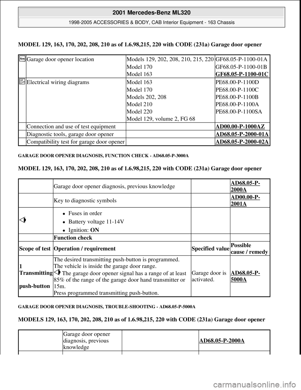
MODEL 129, 163, 170, 202, 208, 210 as of 1.6.98,215, 220 with CODE (231a) Garage door opener
GARAGE DOOR OPENER DIAGNOSIS, FUNCTION CHECK - AD68.05-P-3000A
MODEL 129, 163, 170, 202, 208, 210 as of 1.6.98,215, 220 with CODE (231a) Garage door opener
GARAGE DOOR OPENER DIAGNOSIS, TROUBLE-SHOOTING - AD68.05-P-5000A
MODELS 129, 163, 170, 202, 208, 210 as of 1.6.98,215, 220 with CODE (231a) Garage door opener
Garage door opener locationModels 129, 202, 208, 210, 215, 220GF68.05-P-1100-01A
Model 170GF68.05-P-1100-01B
Model 163GF68.05-P-1100-01C
Electrical wiring diagramsModel 163PE68.00-P-1100D
Model 170PE68.00-P-1100C
Models 202, 208PE68.00-P-1100B
Model 210PE68.00-P-1100A
Model 220PE68.00-P-1100SA
Model 129, volume 2, FG 68
Connection and use of test equipment AD00.00-P-1000AZ
Diagnostic tools, garage door opener AD68.05-P-2000-01A
Compatibility test for garage door opener AD68.05-P-2000-02A
Garage door opener diagnosis, previous knowledge AD68.05-P-
2000A
Key to diagnostic symbols AD00.00-P-
2001A
Fuses in order
Battery voltage 11-14V
Ignition: ON
Function check
Scope of test Operation / requirement Specified value Possible
cause / remedy
1
Transmitting
push-button
The desired transmitting push-button is programmed.
The vehicle is inside the garage door range.
The garage door opener signal has a range of at least
85% of the range of the garage door hand transmitter or
15m.
Press programmed transmitting push-button.
Garage door is
activated.AD68.05-P-
5000A
Garage door opener
diagnosis, previous
knowledge
AD68.05-P-2000A
2001 Mercedes-Benz ML320
1998-2005 ACCESSORIES & BODY, CAB Interior Equipment - 163 Chassis
me
Saturday, October 02, 2010 3:35:21 PMPage 10 © 2006 Mitchell Repair Information Company, LLC.
Page 3542 of 4133
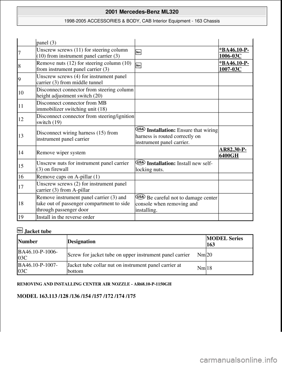
Jacket tube
REMOVING AND INSTALLING CENTER AIR NOZZLE - AR68.10-P-1150GH
MODEL 163.113 /128 /136 /154 /157 /172 /174 /175
panel (3)
7Unscrew screws (11) for steering column
(10) from instrument panel carrier (3) *BA46.10-P-
1006-03C
8Remove nuts (12) for steering column (10)
from instrument panel carrier (3) *BA46.10-P-
1007-03C
9Unscrew screws (4) for instrument panel
carrier (3) from middle tunnel
10Disconnect connector from steering column
height adjustment switch (20)
11Disconnect connector from MB
immobilizer switching unit (18)
12Disconnect connector from steering/ignition
switch (19)
13Disconnect wiring harness (15) from
instrument panel carrier Installation:Ensure that wiring
harness is routed correctly on
instrument panel carrier.
14Remove wiper system AR82.30-P-
6400GH
15Unscrew nuts for instrument panel carrier
(3) on firewall Installation: Install new self-
locking nuts.
16Remove caps on A-pillar (1)
17Unscrew screws (2) for instrument panel
carrier (3) from A-pillar
18
Remove instrument panel carrier (3) and
take out of passenger compartment to side
through passenger doorBe careful not to damage center
console when removing and
installing.
19Install in the reverse order
NumberDesignationMODEL Series
163
BA46.10-P-1006-
03CScrew for jacket tube on upper instrument panel carrierNm20
BA46.10-P-1007-
03CJacket tube collar nut on instrument panel carrier at
bottomNm18
2001 Mercedes-Benz ML320
1998-2005 ACCESSORIES & BODY, CAB Interior Equipment - 163 Chassis
me
Saturday, October 02, 2010 3:35:21 PMPage 24 © 2006 Mitchell Repair Information Company, LLC.
Page 3557 of 4133
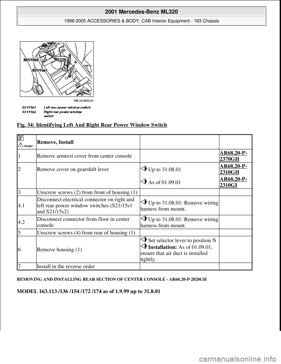
Fig. 34: Identifying Left And Right Rear Power Window Switch
REMOVING AND INSTALLING REAR SECTION OF CENTER CONSOLE - AR68.20-P-2020GH
MODEL 163.113 /136 /154 /172 /174 as of 1.9.99 up to 31.8.01
Remove, Install
1Remove armrest cover from center console AR68.20-P-
2370GH
2Remove cover on gearshift lever Up to 31.08.01AR68.20-P-
2310GH
As of 01.09.01AR68.20-P-
2310GI
3Unscrew screws (2) from front of housing (1)
4.1
Disconnect electrical connector on right and
left rear power window switches (S21/15s1
and S21/15s2)Up to 31.08.01: Remove wiring
harness from mount.
4.2Disconnect connector from floor in center
consoleUp to 31.08.01: Remove wiring
harness from mount.
5Unscrew screws (4) from rear of housing (1)
6Remove housing (1)
Set selector lever to position N
Installation: As of 01.09.01,
ensure that air duct is installed
tightly.
7Install in the reverse order
2001 Mercedes-Benz ML320
1998-2005 ACCESSORIES & BODY, CAB Interior Equipment - 163 Chassis
me
Saturday, October 02, 2010 3:35:22 PMPage 39 © 2006 Mitchell Repair Information Company, LLC.