1997 MERCEDES-BENZ ML430 wiring
[x] Cancel search: wiringPage 3565 of 4133
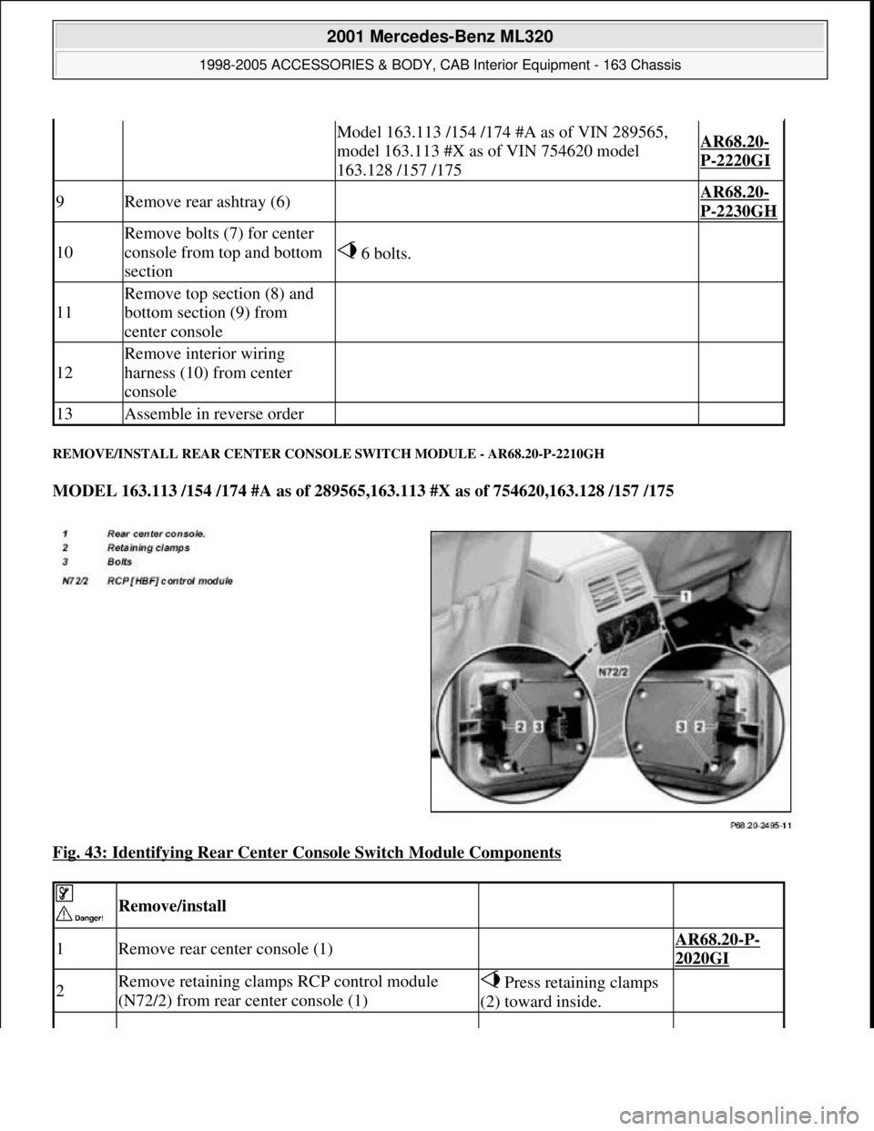
REMOVE/INSTALL REAR CENTER CONSOLE SWITCH MODULE - AR68.20-P-2210GH
MODEL 163.113 /154 /174 #A as of 289565,163.113 #X as of 754620,163.128 /157 /175
Fig. 43: Identifying Rear Center Console Switch Module Components
Model 163.113 /154 /174 #A as of VIN 289565,
model 163.113 #X as of VIN 754620 model
163.128 /157 /175AR68.20-
P-2220GI
9Remove rear ashtray (6) AR68.20-
P-2230GH
10
Remove bolts (7) for center
console from top and bottom
section
6 bolts.
11
Remove top section (8) and
bottom section (9) from
center console
12
Remove interior wiring
harness (10) from center
console
13Assemble in reverse order
Remove/install
1Remove rear center console (1) AR68.20-P-
2020GI
2Remove retaining clamps RCP control module
(N72/2) from rear center console (1) Press retaining clamps
(2) toward inside.
2001 Mercedes-Benz ML320
1998-2005 ACCESSORIES & BODY, CAB Interior Equipment - 163 Chassis
me
Saturday, October 02, 2010 3:35:22 PMPage 47 © 2006 Mitchell Repair Information Company, LLC.
Page 3584 of 4133
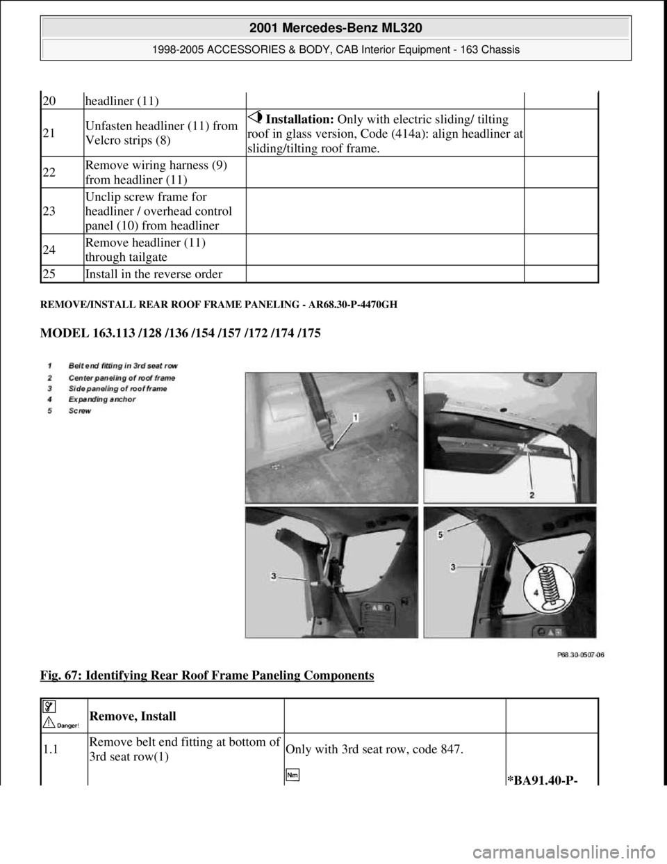
REMOVE/INSTALL REAR ROOF FRAME PANELING - AR68.30-P-4470GH
MODEL 163.113 /128 /136 /154 /157 /172 /174 /175
Fig. 67: Identifying Rear Roof Frame Paneling Components
20headliner (11)
21Unfasten headliner (11) from
Velcro strips (8) Installation: Only with electric sliding/ tilting
roof in glass version, Code (414a): align headliner at
sliding/tilting roof frame.
22Remove wiring harness (9)
from headliner (11)
23
Unclip screw frame for
headliner / overhead control
panel (10) from headliner
24Remove headliner (11)
through tailgate
25Install in the reverse order
Remove, Install
1.1Remove belt end fitting at bottom of
3rd seat row(1)Only with 3rd seat row, code 847.
*BA91.40-P-
2001 Mercedes-Benz ML320
1998-2005 ACCESSORIES & BODY, CAB Interior Equipment - 163 Chassis
me
Saturday, October 02, 2010 3:35:22 PMPage 66 © 2006 Mitchell Repair Information Company, LLC.
Page 3592 of 4133
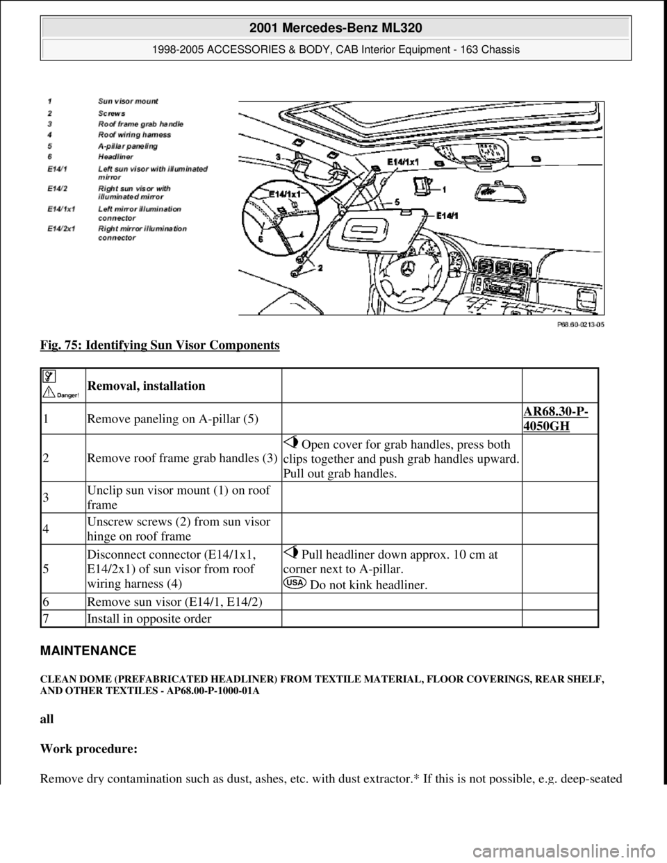
Fig. 75: Identifying Sun Visor Components
MAINTENANCE
CLEAN DOME (PREFABRICATED HEADLINER) FROM TEXTILE MATERIAL, FLOOR COVERINGS, REAR SHELF,
AND OTHER TEXTILES - AP68.00-P-1000-01A
all
Work procedure:
Remove dr
y contamination such as dust, ashes, etc. with dust extractor.* If this is not possible, e.g. deep-seated
Removal, installation
1Remove paneling on A-pillar (5) AR68.30-P-
4050GH
2Remove roof frame grab handles (3)
Open cover for grab handles, press both
clips together and push grab handles upward.
Pull out grab handles.
3Unclip sun visor mount (1) on roof
frame
4Unscrew screws (2) from sun visor
hinge on roof frame
5
Disconnect connector (E14/1x1,
E14/2x1) of sun visor from roof
wiring harness (4) Pull headliner down approx. 10 cm at
corner next to A-pillar.
Do not kink headliner.
6Remove sun visor (E14/1, E14/2)
7Install in opposite order
2001 Mercedes-Benz ML320
1998-2005 ACCESSORIES & BODY, CAB Interior Equipment - 163 Chassis
me
Saturday, October 02, 2010 3:35:22 PMPage 74 © 2006 Mitchell Repair Information Company, LLC.
Page 3599 of 4133
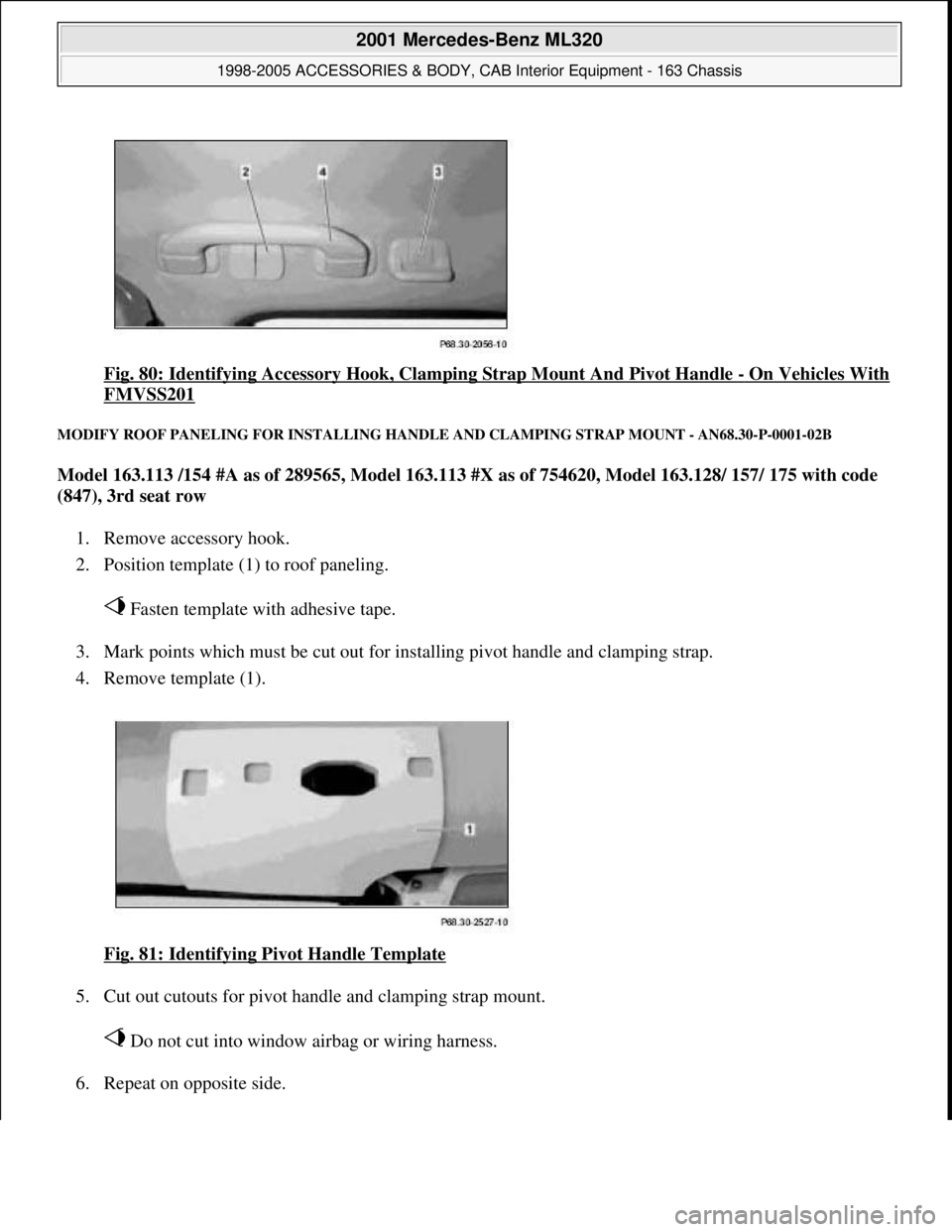
Fig. 80: Identifying Accessory Hook, Clamping Strap Mount And Pivot Handle - On Vehicles With
FMVSS201
MODIFY ROOF PANELING FOR INSTALLING HANDLE AND CLAMPING STRAP MOUNT - AN68.30-P-0001-02B
Model 163.113 /154 #A as of 289565, Model 163.113 #X as of 754620, Model 163.128/ 157/ 175 with code
(847), 3rd seat row
1. Remove accessory hook.
2. Position template (1) to roof paneling.
Fasten template with adhesive tape.
3. Mark points which must be cut out for installing pivot handle and clamping strap.
4. Remove template (1).
Fig. 81: Identifying Pivot Handle Template
5. Cut out cutouts for pivot handle and clamping strap mount.
Do not cut into window airbag or wiring harness.
6. Repeat on opposite side.
2001 Mercedes-Benz ML320
1998-2005 ACCESSORIES & BODY, CAB Interior Equipment - 163 Chassis
me
Saturday, October 02, 2010 3:35:22 PMPage 81 © 2006 Mitchell Repair Information Company, LLC.
Page 3745 of 4133

2.1
Detach automatic transmission from engine
Models 463.206/ 209/ 232/ 233/ 240/ 241
AR27.10-P-0500BD
Models 463.243/ 244/ 245/ 246/ 247/ 248/
249/ 250/ 254
AR27.10-P-0500GA
Model 230.475
AR27.10-P-0500R
Model 230.474
Model 220 without 4MATIC
AR27.10-P-0500I
Model 220 with 4MATIC
AR27.10-P-0500IW
Models 129, 170, 202, 208, 210
AR27.10-P-0500B
Model 203 without 4MATIC, 209 with Engine
112,113
AR27.10-P-0500P
Model 203 with 4MATIC
AR27.10-P-0500PW
Model 211.061/065/070
AR27.10-P-0500T
Model 163
AR27.10-P-0500GH
2.2
Detach manual transmission from engine
Models 129, 202, 210
AR26.10-P-0020A
Models 203, 209 with Engine 112
AR26.10-P-0020P
Model 211.061
AR26.10-P-0020T
Model 208 with transmission 716.662/622
AR26.10-P-0020E
Model 170,
Model 208 with transmission 716.663
AR26.10-P-0020D
3
Detach top part of oil pan
Models 463.206/ 209/ 232/ 233/ 240/ 241/
243/ 244/ 245/ 246/ 247/ 248/ 249/ 250/ 254
AR01.45-P-7500FG
Model 230.474/
AR01.45-P-7500R
Model 220 without 4MATIC
AR01.45-P-7500I
Model 220 with 4MATIC
AR01.45-P-7500IW
Model 210 with 4MATIC
AR01.45-P-7500FA
Model 210 without 4MATIC
AR01.45-P-7500F
Models 202, 208
AR01.45-P-7500FC
Model 203 without 4MATIC, 209 with Engine
112,113
AR01.45-P-7500PV
Model 203 with 4MATIC
AR01.45-P-7500PW
Models 211.061/065/070
AR01.45-P-7500TV
Model 170
AR01.45-P-7500SV
Model 163
AR01.45-P-7500FB
Model 129
AR01.45-P-7500FD
4
Take off cylinder head
Remove intake manifold with complete
wiring loom during this step.
Models 463.206/ 209/ 232/ 233/ 240/ 241/
243/ 244/ 245/ 246/ 247/ 248/ 249/ 250/ 254
AR01.30-P-5800GV
Engine 112 in model 129 and engine 113 in
models 129, 202, 208, 210
AR01.30-P-5800B
Engine 112 in models 170, 202, 208, 210,
220 and engine 113 in models 220,
230.474 /475
AR01.30-P-5800BA
Model 163
AR01.30-P-5800MV
Models 203, 209 with engine 112, 113
Models 211.061/065/070
AR01.30-P-5800PV
5
Remove oil pump
Push back chain tensioner for this step
and take off chain.
All except models 203, 209, 211.061/065/070,
220 without 4MATIC, 230.474 /475
AR18.10-P-6020B
Model 203 without 4MATIC, 209,
211.061/065/070
AR18.10-P-6020PV
Model 203 with 4MATIC, model 220 with
4MATIC
AR18.10-P-6020PW
Model 230.474/475
AR18.10-P-6020R
6
Remove conrod bearing cap (5)
For this step, mark conrod (4) and
connecting rod bearing cap (5) on one side
relative to each other.
7
Remove conrod (4) together with pistons (3)
by lifting up and out
If pistons have been used (3), the arrows
indicating the direction of the travel and the
markings on the pistons may no longer be
visible due to carbon deposits. For this
reason, remove the carbon deposits from the
pistons. If the arrows indicating direction of
travel on the pistons are no longer
recognizable, these must be re-marked.
8
Remove circlip (1) of piston pin (2)
Do not damage piston (3). Place a clean
cloth underneath.
9
Press out piston pin (2)
Installing
10
Assign piston (3) to cylinder bore
AR03.10-P-7021-02BV
Copyright DaimlerChrysler AG 20.05.2006 CD-Ausgabe G/10/04 . This WIS print-out will not be recorde
d by Modification services.
Page 2
Page 3759 of 4133
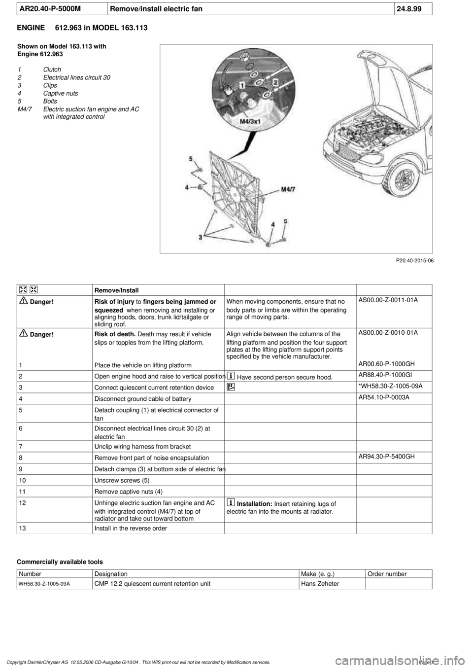
AR20.40-P-5000M
Remove/install electric fan
24.8.99
ENGINE
612.963 in MODEL 163.113
P20.40-2015-06
Shown on Model 163.113 with
Engine 612.963
1
Clutch
2
Electrical lines circuit 30
3
Clips
4
Captive nuts
5
Bolts
M4/7
Electric suction fan engine and AC
with integrated control
Remove/Install
Danger!
Risk of injury
to
fingers being jammed or
squeezed
when removing and installing or
aligning hoods, doors, trunk lid/tailgate or
sliding roof.
When moving components, ensure that no
body parts or limbs are within the operating
range of moving parts.
AS00.00-Z-0011-01A
Danger!
Risk of death.
Death may result if vehicle
slips or topples from the lifting platform.
Align vehicle between the columns of the
lifting platform and position the four support
plates
at the lifting platform support points
specified by the vehicle manufacturer.
AS00.00-Z-0010-01A
1
Place the vehicle on lifting platform
AR00.60-P-1000GH
2
Open engine hood and raise to vertical position
Have second person secure hood.
AR88.40-P-1000GI
3
Connect quiescent current retention device
*WH58.30-Z-1005-09A
4
Disconnect ground cable of battery
AR54.10-P-0003A
5
Detach coupling (1) at electrical connector of
fan
6
Disconnect electrical lines circuit 30 (2) at
electric fan
7
Unclip wiring harness from bracket
8
Remove front part of noise encapsulation
AR94.30-P-5400GH
9
Detach clamps (3) at bottom side of electric fan
10
Unscrew screws (5)
11
Remove captive nuts (4)
12
Unhinge electric suction fan engine and AC
with integrated control (M4/7) at top of
radiator and take out toward bottom
Installation:
Insert retaining lugs of
electric fan into the mounts at radiator.
13
Install in the reverse order
Commercially available tools
Number
Designation
Make (e. g.)
Order number
WH58.30-Z-1005-09A
CMP 12.2 quiescent current retention unit
Hans Zeheter
Copyright DaimlerChrysler AG 12.05.2006 CD-Ausgabe G/10/04 . This WIS print-out will not be recorde
d by Modification services.
Page 1
Page 3785 of 4133
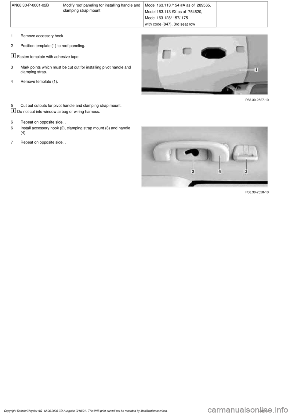
AN68.30-P-0001-02B
Modify roof paneling for installing handle and
clamping strap mount
Model 163.113 /154 #A as of 289565,
Model 163.113 #X as of 754620,
Model 163.128/ 157/ 175
with code (847), 3rd seat row
P68.30-2527-10
1
Remove accessory hook.
2
Position template (1) to roof paneling.
Fasten template with adhesive tape.
3
Mark points which must be cut out for installing pivot handle and
clamping strap.
4
Remove template (1).
5
Cut out cutouts for pivot handle and clamping strap mount.
Do not cut into window airbag or wiring harness.
6
Repeat on opposite side. .
P68.30-2528-10
6
Install accessory hook (2), clamping strap mount (3) and handle
(4).
7
Repeat on opposite side. .
Copyright DaimlerChrysler AG 12.06.2006 CD-Ausgabe G/10/04 . This WIS print-out will not be recorde
d by Modification services.
Page 1
Page 3789 of 4133
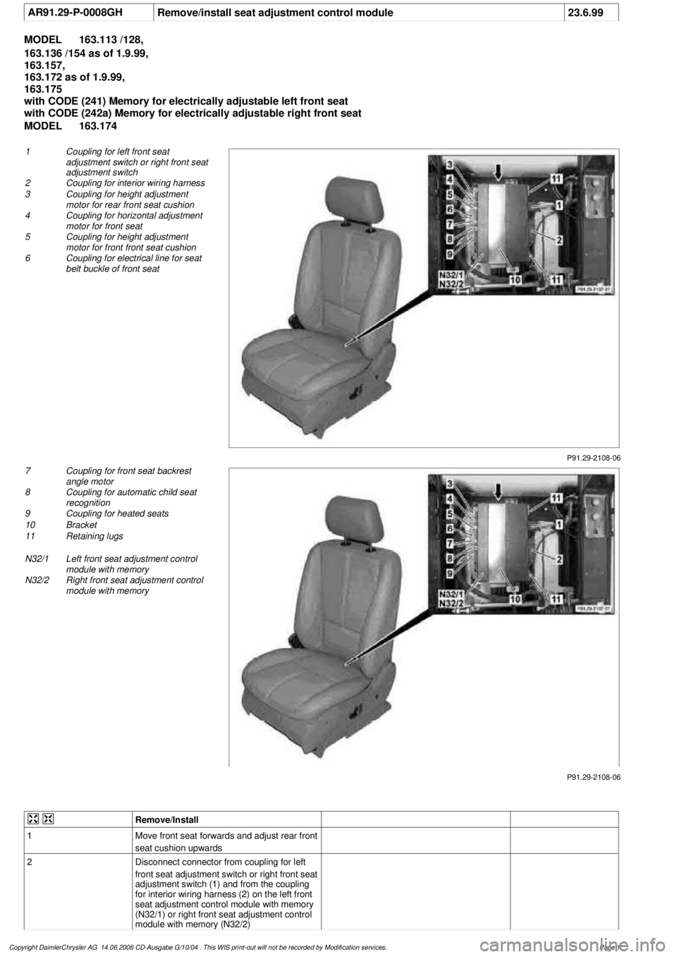
AR91.29-P-0008GH
Remove/install seat adjustment control module
23.6.99
MODEL
163.113 /128,
163.136 /154 as of 1.9.99,
163.157,
163.172 as of 1.9.99,
163.175
with CODE (241) Memory for electrically adjustable left front seat
with CODE (242a) Memory for electrically adjustable right front seat
MODEL
163.174
P91.29-2108-06
1
Coupling for left front seat
adjustment switch or right front seat
adjustment switch
2
Coupling for interior wiring harness
3
Coupling for height adjustment
motor for rear front seat cushion
4
Coupling for horizontal adjustment
motor for front seat
5
Coupling for height adjustment
motor for front front seat cushion
6
Coupling for electrical line for seat
belt buckle of front seat
P91.29-2108-06
7
Coupling for front seat backrest
angle motor
8
Coupling for automatic child seat
recognition
9
Coupling for heated seats
10
Bracket
11
Retaining lugs
N32/1
Left front seat adjustment control
module with memory
N32/2
Right front seat adjustment control
module with memory
Remove/Install
1
Move front seat forwards and adjust rear front
seat cushion upwards
2
Disconnect connector from coupling for left
front seat adjustment switch or right front seat
adjustment switch (1) and from the coupling
for interior wiring harness (2) on the left front
seat adjustment control module with memory
(N32/1) or right front seat adjustment control
module with memory (N32/2)
Copyright DaimlerChrysler AG 14.06.2006 CD-Ausgabe G/10/04 . This WIS print-out will not be recorde
d by Modification services.
Page 1