Page 3415 of 4133

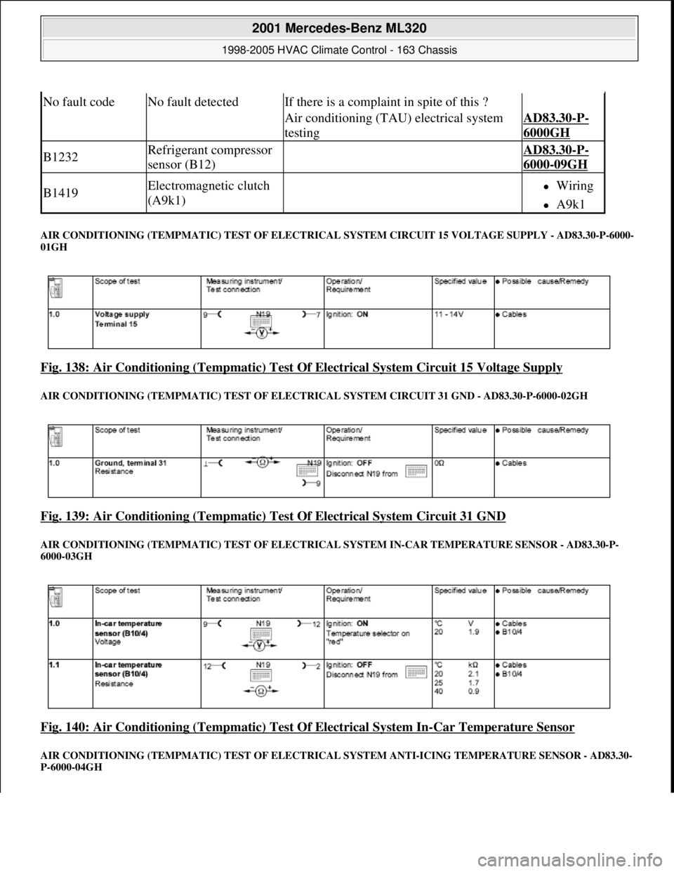
AIR CONDITIONING (TEMPMAT IC) TEST OF ELECTRICAL SYSTEM CIRCUIT 15 VOLTAGE SUPPLY - AD83.30-P-6000-
01GH
Fig. 138: Air Conditioning (Tem pmatic) Test Of Electrical System Circuit 15 Voltage Supply
AIR CONDITIONING (TEM PMATIC) TEST OF ELECTRICAL SYST EM CIRCUIT 31 GND - AD83.30-P-6000-02GH
Fig. 139: Air Conditioning (Tempmatic) Test Of Electrical System Circuit 31 GND
AIR CONDITIONING (TEMPM ATIC) TEST OF ELECTRICAL SYSTEM IN-CAR TEMPERA TURE SENSOR - AD83.30-P-
6000-03GH
Fig. 140: Air Conditioning (Tempmat ic) Test Of Electrical System In-Car Temperature Sensor
AIR CONDITIONING (TEMPMATIC) TEST OF ELECTRICAL SYSTEM ANTI-ICING TEM PERATURE SENSOR - AD83.30-
P-6000-04GH
No fault codeNo fault detectedIf there is a complaint in spite of this ?
Air conditioning (TAU) electrical system
testingAD83.30-P-
6000GH
B1232Refrigerant compressor
sensor (B12) AD83.30-P-
6000-09GH
B1419Electromagnetic clutch
(A9k1) Wiring
A9k1
2001 Mercedes-Benz ML320
1998-2005 HVAC Climate Control - 163 Chassis
me
Saturday, October 02, 2010 3:23:17 PMPage 171 © 2006 Mitchell Repair Information Company, LLC.
Page 3418 of 4133

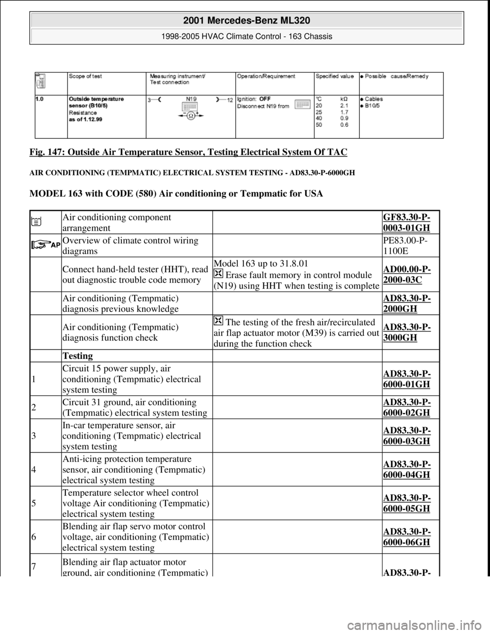
Fig. 147: Outside Air Temperature Sensor, Testing Electrical System Of TAC
AIR CONDITIONING (TEMPMATIC) ELECTRICAL SYSTEM TESTING - AD83.30-P-6000GH
MODEL 163 with CODE (580) Air conditioning or Tempmatic for USA
Air conditioning component
arrangement GF83.30-P-
0003-01GH
Overview of climate control wiring
diagrams PE83.00-P-
1100E
Connect hand-held tester (HHT), read
out diagnostic trouble code memoryModel 163 up to 31.8.01
Erase fault memory in control module
(N19) using HHT when testing is completeAD00.00-P-
2000-03C
Air conditioning (Tempmatic)
diagnosis previous knowledge AD83.30-P-
2000GH
Air conditioning (Tempmatic)
diagnosis function check The testing of the fresh air/recirculated
air flap actuator motor (M39) is carried out
during the function checkAD83.30-P-
3000GH
Testing
1
Circuit 15 power supply, air
conditioning (Tempmatic) electrical
system testing
AD83.30-P-
6000-01GH
2Circuit 31 ground, air conditioning
(Tempmatic) electrical system testing AD83.30-P-
6000-02GH
3
In-car temperature sensor, air
conditioning (Tempmatic) electrical
system testing
AD83.30-P-
6000-03GH
4
Anti-icing protection temperature
sensor, air conditioning (Tempmatic)
electrical system testing
AD83.30-P-
6000-04GH
5
Temperature selector wheel control
voltage Air conditioning (Tempmatic)
electrical system testing
AD83.30-P-
6000-05GH
6
Blending air flap servo motor control
voltage, air conditioning (Tempmatic)
electrical system testing
AD83.30-P-
6000-06GH
7Blending air flap actuator motor
ground, air conditioning (Tempmatic) AD83.30-P-
2001 Mercedes-Benz ML320
1998-2005 HVAC Climate Control - 163 Chassis
me
Saturday, October 02, 2010 3:23:17 PMPage 174 © 2006 Mitchell Repair Information Company, LLC.
Page 3434 of 4133
Fig. 158: Identifying Components Of Defroster Vent Flap Actuator Motor For Windshield
REMOVE/INSTALL FOOTWELL FLAP ACTUATOR MOTOR - AR83.30-P-2007GH
Remove/install
1Remove cover below instrument
panel (left) AR68.10-P-
1500GH
2.1Remove electronic transmission
control (ETC) control module Only on models fitted with automatic
transmission.AR27.19-P-
1719GH
3
Disconnect interior and taillamp
wiring harness connector, cockpit
(X18)from bracket(1)
4Remove screws (2)
5Move bracket (1) downwards and
put to one side
6Disconnect plug (3)
7
Remove screws (4) on defroster vent
flap actuator motor (M2/8) from
heater housing
8Remove defroster vent flap actuator
motor (M2/8) Installation:Adjust defroster vent flap
actuator motor (M2/8) to the 0 position
using STAR DIAGNOSIS.
9Install in the reverse order
2001 Mercedes-Benz ML320
1998-2005 HVAC Climate Control - 163 Chassis
me
Saturday, October 02, 2010 3:23:18 PMPage 190 © 2006 Mitchell Repair Information Company, LLC.
Page 3435 of 4133
MODELS 163.113 #A as of 289565, 163.113 #X as of 754620, 163.154 /174 #A as of 289565,
163.128/157/175
Fig. 159: Identifying Footwell Flap Actuator Motor Components
Remove/install
1Remove cover below
instrument panel (left) AR68.10-P-
1500GH
2.1 Remove electronic
transmission control
(ETC) control module
Only on models fitted with
automatic transmission.AR27.19-P-
1719GH
3
Disconnect interior and
taillamp wiring harness
connector, cockpit(X18)from
bracket(1)
4Remove screws (2)
5Move bracket (1) downwards
and put to one side
6Disconnect connector (3)
7
Remove screws (4) on defroster
vent flap actuator motor
(M2/15) from heater housing
8
M2/15 Remove footwell flap
Installation: Adjust footwell
flap actuator motor (M2/15) to the
2001 Mercedes-Benz ML320
1998-2005 HVAC Climate Control - 163 Chassis
me
Saturday, October 02, 2010 3:23:18 PMPage 191 © 2006 Mitchell Repair Information Company, LLC.
Page 3436 of 4133
REMOVE/INSTALL REAR SHUTOFF FLAP ACTUATOR MOTOR - AR83.30-P-2008GH
MODEL 163.113 /154 /174 #A as of 289565, 163.113 #X as of 754620, 163.128/157/175
Fig. 160: Identifying Rear Shutoff Flap Actuator Motor Components
actuator motor0 position using STAR
DIAGNOSIS.
9Install in the reverse order
Remove/install
1Remove cover below
instrument panel (left) AR68.10-P-
1500GH
2.1 Remove electronic
transmission control
(ETC) control module
Only on models fitted with
automatic transmission.AR27.19-P-
1719GH
3
Disconnect interior and taillamp
wiring harness connector,
cockpit(X18)from bracket(1)
4Remove screws (2)
5Move bracket (1) downwards
and put to one side
6Disconnect plug (3)
Remove screws (4) on rear
2001 Mercedes-Benz ML320
1998-2005 HVAC Climate Control - 163 Chassis
me
Saturday, October 02, 2010 3:23:18 PMPage 192 © 2006 Mitchell Repair Information Company, LLC.
Page 3465 of 4133

Dashboard
Air conditioning system
8Remove wiper system AR82.30-P-
6400GH
9Remove nuts (5) from instrument
panel at firewall
*BA68.10-
P-1001-
01A
10Remove paneling from A-pillar AR68.30-P-
4050GH
11Remove plastic nuts on driver's side
at paneling below instrument panel
12Remove paneling on right in footwell AR68.30-P-
4010GH
13
Remove rubber covers on side at the
A-pillars and unscrew screws for
instrument panel at A-pillar (arrows)
*BA68.10-
P-1002-
01A
14Remove center console AR68.20-P-
2000GH
15Unscrew bolt (6) underneath the
instrument panel
*BA68.10-
P-1003-
01A
16Withdraw instrument panel to the
rear Bring in helper. Cushion front edge of
selector lever module so that lower edge of
instrument panel is not damaged.
17Turn instrument panel around so that
the back is accessible Do not overstretch interior wiring
harness.
18Detach outside temperature sensor
connector (B10/5x1)
19Disconnect cable from temperature
sensor to evaporator housing Installation: Ensure clean cable routing.
20Remove outside temperature sensor
(B10/5) from air duct 2 bolts.
21Install in the reverse order
22Inspect cooling system for leaks AR20.00-P-
1010HA
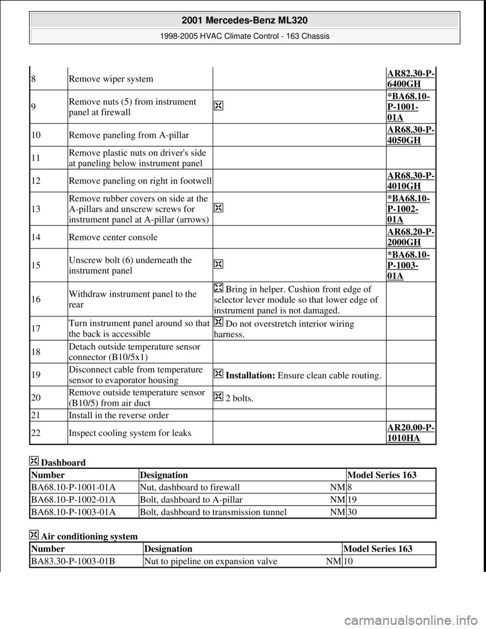
NumberDesignationModel Series 163
BA68.10-P-1001-01ANut, dashboard to firewallNM8
BA68.10-P-1002-01ABolt, dashboard to A-pillarNM19
BA68.10-P-1003-01ABolt, dashboard to transmission tunnelNM30
NumberDesignationModel Series 163
BA83.30-P-1003-01BNut to pipeline on expansion valveNM10
2001 Mercedes-Benz ML320
1998-2005 HVAC Climate Control - 163 Chassis
me
Saturday, October 02, 2010 3:23:19 PMPage 221 © 2006 Mitchell Repair Information Company, LLC.
Page 3469 of 4133
Fig. 181: Identifying Components Of In-Car Temperature Sensor For Aspirator Blower
REMOVE/INSTALL SWITCH UNIT/AUTOMATIC AIR CONDITIONING CONTROL MODULE - AR83.40-P-6500GH
Removal, installation
1Remove ETC control module AR27.19-P-
1719GH
2Detach connector for interior/rear lamp
wiring harness (X18) at ETC bracket (1) Release clamp on back of
bracket and slide connector
forward.
3Disconnect connector (X18)
4Unscrew bolts (2)
5Lay bracket (1) downward and to the side
6Detach hose (3) at aspirator blower (M9)
7Detach clip (5) of aspirator blower
connector at instrument panel bracket
8Disconnect in-car temperature sensor
aspirator blower's connector
9Unscrew bolts (4)
10Remove in-car temperature sensor
aspirator blower (M9)
11Install in the reverse order
2001 Mercedes-Benz ML320
1998-2005 HVAC Climate Control - 163 Chassis
me
Saturday, October 02, 2010 3:23:19 PMPage 225 © 2006 Mitchell Repair Information Company, LLC.
Page 3475 of 4133
REMOVAL & INSTALLATION
INSTALL AUXILIARY WIRING HARNESS - SM83.30-P-0009GH
MODEL 163.154 #A up to 289564, 163.154 #X, 163.136 /172 with CODE (580) Air conditioning (or
Tempmatic for USA)
Fig. 188: Identifying Auxiliary Wiring Harness Location
Operation no. of operation texts or standard texts and flat rates
CategoryOp.
no.Operation textTimeAcc.
no.Code
P023731INSTALLING MODIFIED WIRING HARNESS FOR
Additional fan (AFTER CHECKING)015WU/1.3h--
Removing
1Disconnect battery ground
cable AR54.10-P-
0003A
*BA54.10-
P-1017-01C
2Remove rear cover from
fuse and relay module (F1) 5 screws.
3
Remove mounting screws of
fuse holder on fuse and relay
module (F1) and lay down to
2001 Mercedes-Benz ML320
1998-2005 HVAC Climate Control - 163 Chassis
me
Saturday, October 02, 2010 3:23:19 PMPage 231 © 2006 Mitchell Repair Information Company, LLC.