1997 MERCEDES-BENZ ML430 wiring
[x] Cancel search: wiringPage 3029 of 4133
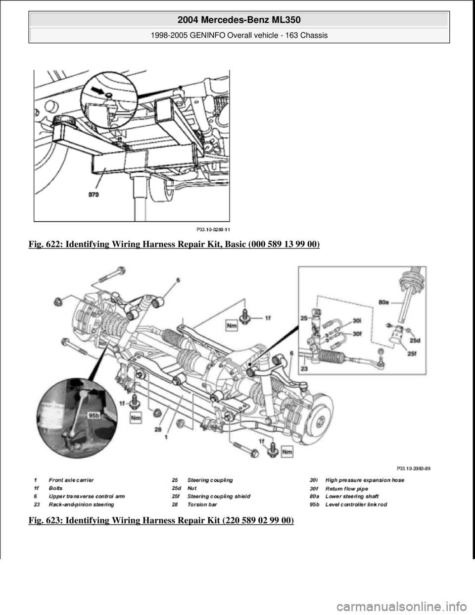
Fig. 622: Identifying Wiring Harness Repair Kit, Basic (000 589 13 99 00)
Fig. 623: Identifying Wiring Ha rness Repair Kit (220 589 02 99 00)
2004 Mercedes-Benz ML350
1998-2005 GENINFO Overall vehicle - 163 Chassis
me
Saturday, October 02, 2010 3:47:51 PMPage 384 © 2006 Mitchell Repair Information Company, LLC.
Page 3033 of 4133
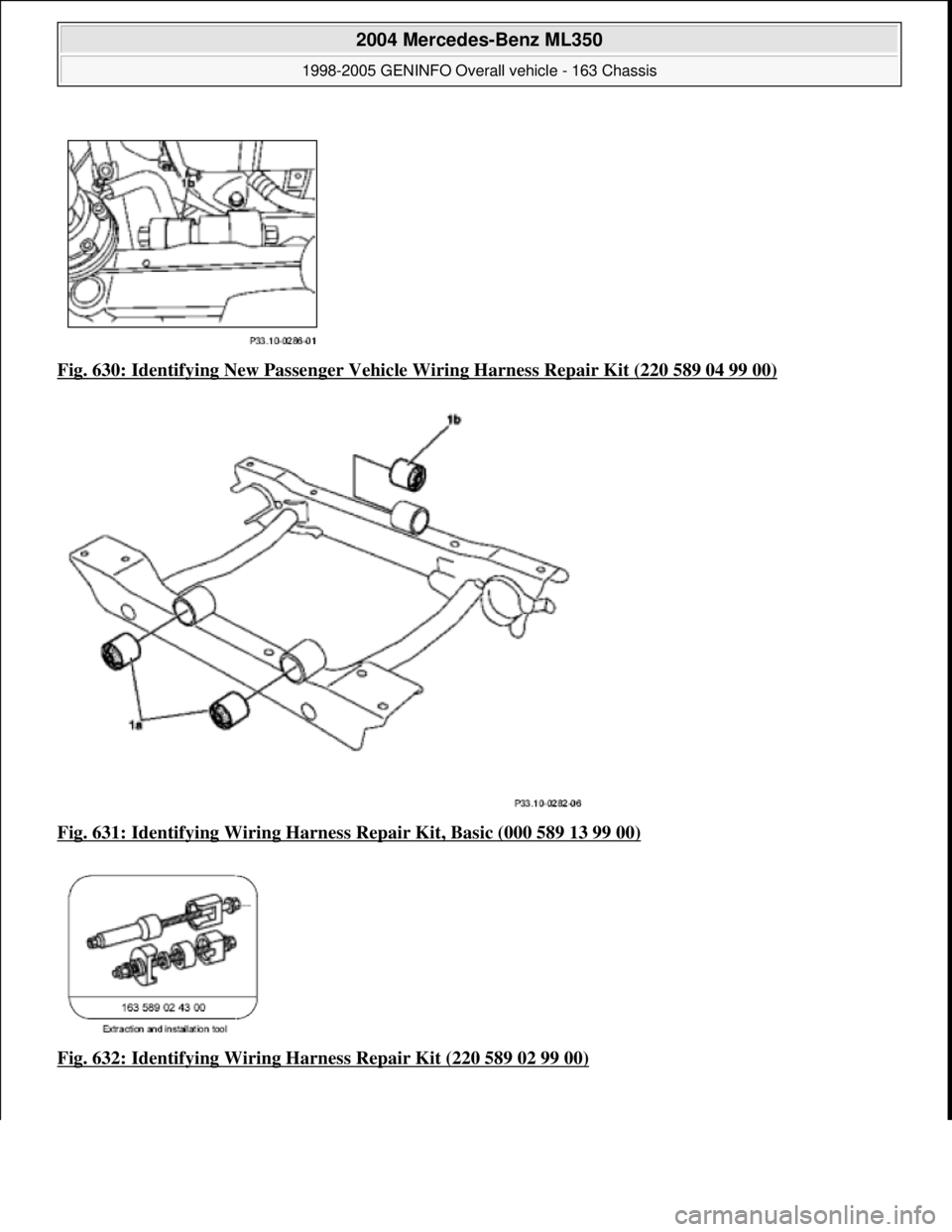
Fig. 630: Identifying New Passe nger Vehicle Wiring Harness Repair Kit (220 589 04 99 00)
Fig. 631: Identifying Wiring Harness Repair Kit, Basic (000 589 13 99 00)
Fig. 632: Identifying Wiring Ha rness Repair Kit (220 589 02 99 00)
2004 Mercedes-Benz ML350
1998-2005 GENINFO Overall vehicle - 163 Chassis
me
Saturday, October 02, 2010 3:47:51 PMPage 388 © 2006 Mitchell Repair Information Company, LLC.
Page 3213 of 4133
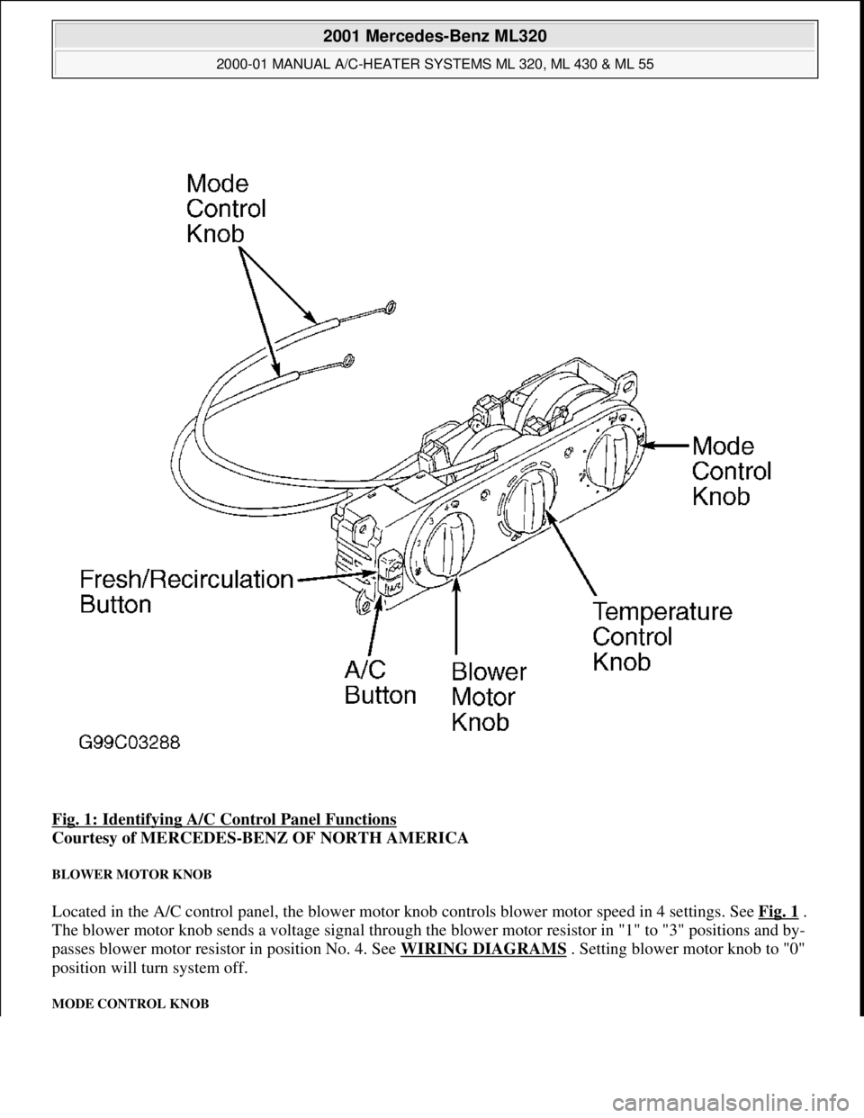
Fig. 1: Identifying A/C Control Panel Functions
Courtesy of MERCEDES-BENZ OF NORTH AMERICA
BLOWER MOTOR KNOB
Located in the A/C control panel, the blower motor knob controls blower motor speed in 4 settings. See Fig. 1 .
The blower motor knob sends a voltage signal through the blower motor resistor in "1" to "3" positions and by-
passes blower motor resistor in position No. 4. See WIRING DIAGRAMS . Setting blower motor knob to "0"
position will turn system off.
MODE CONTROL KNOB
2001 Mercedes-Benz ML320
2000-01 MANUAL A/C-HEATER SYSTEMS ML 320, ML 430 & ML 55
me
Saturday, October 02, 2010 3:25:10 PMPage 2 © 2006 Mitchell Repair Information Company, LLC.
Page 3218 of 4133
CLIMATE CONTROL DTC
SYSTEM TESTS
CONNECTING TEST EQUIPMENT
Remove radio to gain access to A/C push button control unit harness connector. Turn ignition off. Disconnect
control unit harness connector. Connect socket box Test Cable (163 589 01 63 00) to A/C push button control
unit and wiring harness. See Fig. 3
. Connect test cable to Socket Box (124 589 00 21 00). Connect test
equipment leads to socket box terminals as instructed in circuit tests.
DTCPossible Cause
B1232(1) Refrigerant Pressure Sensor
B1419Electromagnetic Clutch
(1)Check A/C refrigerant pressure sensor. See A/C REFRIGERANT PRESSURE SWITCH under
ELECTRICAL TESTS.
WARNING:To avoid injury from Accidental air bag deployment, read and carefully
follow all SERVICE PRECAUTIONS and DISABLING & ACTIVATING AIR
BAG SYSTEM procedures in AIR BAG SYSTEM SAFETY article in
GENERAL SERVICING.
2001 Mercedes-Benz ML320
2000-01 MANUAL A/C-HEATER SYSTEMS ML 320, ML 430 & ML 55
me
Saturday, October 02, 2010 3:25:10 PMPage 7 © 2006 Mitchell Repair Information Company, LLC.
Page 3220 of 4133
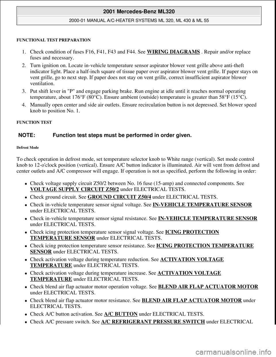
FUNCTIONAL TEST PREPARATION
1. Check condition of fuses F16, F41, F43 and F44. See WIRING DIAGRAMS . Repair and/or replace
fuses and necessary.
2. Turn ignition on. Locate in-vehicle temperature sensor aspirator blower vent grille above anti-theft
indicator light. Place a half-inch square of tissue paper over aspirator blower vent grille. If paper stays on
vent grille, go to next step. If paper does not stay on vent grille, correct insufficient aspirator blower
ventilation.
3. Put shift lever in "P" and engage parking brake. Run engine at idle until it reaches normal operating
temperature, about 176°F (80°C). Ensure ambient (outside) temperature is greater than 58°F (15°C).
4. Manually open center and side air outlets. Ensure recirculation button is not depressed. Set blower speed
knob to position No. 1.
FUNCTION TEST
Defrost Mode
To check operation in defrost mode, set temperature selector knob to White range (vertical). Set mode control
knob to 12-o'clock position (vertical). Ensure A/C button indicator is illuminated. Air will vent from defrost and
center outlets and A/C compressor will engage. If operation is not as specified, perform the following in order:
Check voltage supply circuit Z50/2 between No. 16 fuse (15-amp) and connected components. See
VOLTAGE SUPPLY CIRCUIT Z50/2
under ELECTRICAL TESTS.
Check ground circuit. See GROUND CIRCUIT Z50/4 under ELECTRICAL TESTS.
Check in-vehicle temperature sensor signal voltage. See IN-VEHICLE TEMPERATURE SENSOR
under ELECTRICAL TESTS.
Check in-vehicle temperature sensor signal resistance. See IN-VEHICLE TEMPERATURE SENSOR
under ELECTRICAL TESTS.
Check icing protection temperature sensor signal voltage. See ICING PROTECTION
TEMPERATURE SENSOR under ELECTRICAL TESTS.
Check icing protection temperature sensor resistance. See ICING PROTECTION TEMPERATURE
SENSOR under ELECTRICAL TESTS.
Check activation voltage during temperature reduction. See ACTIVATION VOLTAGE
TEMPERATURE under ELECTRICAL TESTS.
Check activation voltage during temperature increase. See ACTIVATION VOLTAGE
TEMPERATURE under ELECTRICAL TESTS.
Check blend air flap actuator motor operation voltage. See BLEND AIR FLAP ACTUATOR MOTOR
under ELECTRICAL TESTS.
Check blend air flap actuator motor resistance. See BLEND AIR FLAP ACTUATOR MOTOR under
ELECTRICAL TESTS.
Check A/C button activation. See A/C BUTTON under ELECTRICAL TESTS.
Check A/C pressure switch. See A/C REFRIGERANT PRESSURE SWITCH under ELECTRICAL NOTE: Function test steps must be performed in order given.
2001 Mercedes-Benz ML320
2000-01 MANUAL A/C-HEATER SYSTEMS ML 320, ML 430 & ML 55
me
Saturday, October 02, 2010 3:25:10 PMPage 9 © 2006 Mitchell Repair Information Company, LLC.
Page 3221 of 4133
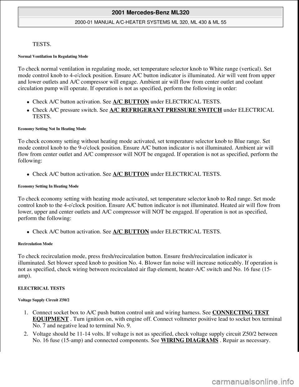
TESTS.
Normal Ventilation In Regulating Mode
To check normal ventilation in regulating mode, set temperature selector knob to White range (vertical). Set
mode control knob to 4-o'clock position. Ensure A/C button indicator is illuminated. Air will vent from upper
and lower outlets and A/C compressor will engage. Ambient air will flow from center outlet and coolant
circulation pump will operate. If operation is not as specified, perform the following in order:
Check A/C button activation. See A/C BUTTON under ELECTRICAL TESTS.
Check A/C pressure switch. See A/C REFRIGERANT PRESSURE SWITCH under ELECTRICAL
TESTS.
Economy Setting Not In Heating Mode
To check economy setting without heating mode activated, set temperature selector knob to Blue range. Set
mode control knob to the 9-o'clock position. Ensure A/C button indicator is not illuminated. Ambient air will
flow from center outlet and A/C compressor will NOT be engaged. If operation is not as specified, perform the
following:
Check A/C button activation. See A/C BUTTON under ELECTRICAL TESTS.
Economy Setting In Heating Mode
To check economy setting with heating mode activated, set temperature selector knob to Red range. Set mode
control knob to the 4-o'clock position. Ensure A/C button indicator is not illuminated. Heated air will flow from
lower, upper and center outlets and A/C compressor will NOT be engaged. If operation is not as specified,
perform the following:
Check A/C button activation. See A/C BUTTON under ELECTRICAL TESTS.
Recirculation Mode
To check recirculation mode, press fresh/recirculation button. Ensure fresh/recirculation indicator is
illuminated. Set blower speed knob to position No. 4. Blower fan noise will increase noticeably. If operation is
not as specified, check wiring between recirculated air flap element, heater-A/C switch and No. 16 fuse (15-
amp).
ELECTRICAL TESTS
Voltage Supply Circuit Z50/2
1. Connect socket box to A/C push button control unit and wiring harness. See CONNECTING TEST
EQUIPMENT . Turn ignition on, with engine off. Connect voltmeter positive lead to socket box terminal
No. 7 and negative lead to terminal No. 9.
2. Voltage should be 11-14 volts. If voltage is not as specified, check voltage supply circuit Z50/2 between
No. 16 fuse (15-amp) and connected components. See WIRING DIAGRAMS
. Repair as necessary.
2001 Mercedes-Benz ML320
2000-01 MANUAL A/C-HEATER SYSTEMS ML 320, ML 430 & ML 55
me
Saturday, October 02, 2010 3:25:10 PMPage 10 © 2006 Mitchell Repair Information Company, LLC.
Page 3222 of 4133
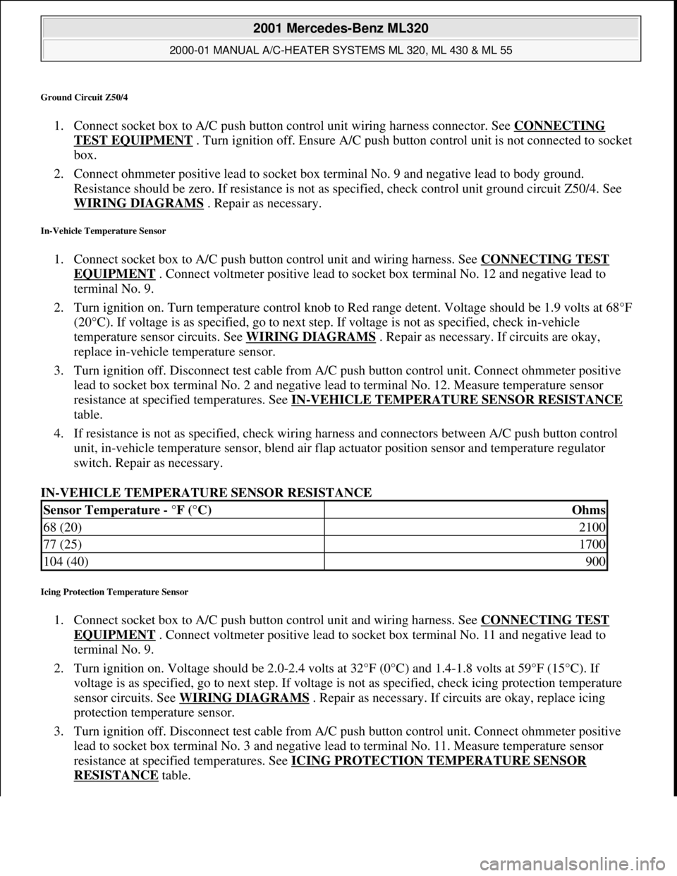
Ground Circuit Z50/4
1. Connect socket box to A/C push button control unit wiring harness connector. See CONNECTING
TEST EQUIPMENT . Turn ignition off. Ensure A/C push button control unit is not connected to socket
box.
2. Connect ohmmeter positive lead to socket box terminal No. 9 and negative lead to body ground.
Resistance should be zero. If resistance is not as specified, check control unit ground circuit Z50/4. See
WIRING DIAGRAMS
. Repair as necessary.
In-Vehicle Temperature Sensor
1. Connect socket box to A/C push button control unit and wiring harness. See CONNECTING TEST
EQUIPMENT . Connect voltmeter positive lead to socket box terminal No. 12 and negative lead to
terminal No. 9.
2. Turn ignition on. Turn temperature control knob to Red range detent. Voltage should be 1.9 volts at 68°F
(20°C). If voltage is as specified, go to next step. If voltage is not as specified, check in-vehicle
temperature sensor circuits. See WIRING DIAGRAMS
. Repair as necessary. If circuits are okay,
replace in-vehicle temperature sensor.
3. Turn ignition off. Disconnect test cable from A/C push button control unit. Connect ohmmeter positive
lead to socket box terminal No. 2 and negative lead to terminal No. 12. Measure temperature sensor
resistance at specified temperatures. See IN
-VEHICLE TEMPERATURE SENSOR RESISTANCE
table.
4. If resistance is not as specified, check wiring harness and connectors between A/C push button control
unit, in-vehicle temperature sensor, blend air flap actuator position sensor and temperature regulator
switch. Repair as necessary.
IN-VEHICLE TEMPERATURE SENSOR RESISTANCE
Icing Protection Temperature Sensor
1. Connect socket box to A/C push button control unit and wiring harness. See CONNECTING TEST
EQUIPMENT . Connect voltmeter positive lead to socket box terminal No. 11 and negative lead to
terminal No. 9.
2. Turn ignition on. Voltage should be 2.0-2.4 volts at 32°F (0°C) and 1.4-1.8 volts at 59°F (15°C). If
voltage is as specified, go to next step. If voltage is not as specified, check icing protection temperature
sensor circuits. See WIRING DIAGRAMS
. Repair as necessary. If circuits are okay, replace icing
protection temperature sensor.
3. Turn ignition off. Disconnect test cable from A/C push button control unit. Connect ohmmeter positive
lead to socket box terminal No. 3 and negative lead to terminal No. 11. Measure temperature sensor
resistance at specified temperatures. See ICING PROTECTION TEMPERATURE SENSOR
RESISTANCE table.
Sensor Temperature - °F (°C)Ohms
68 (20)2100
77 (25)1700
104 (40)900
2001 Mercedes-Benz ML320
2000-01 MANUAL A/C-HEATER SYSTEMS ML 320, ML 430 & ML 55
me
Saturday, October 02, 2010 3:25:10 PMPage 11 © 2006 Mitchell Repair Information Company, LLC.
Page 3223 of 4133
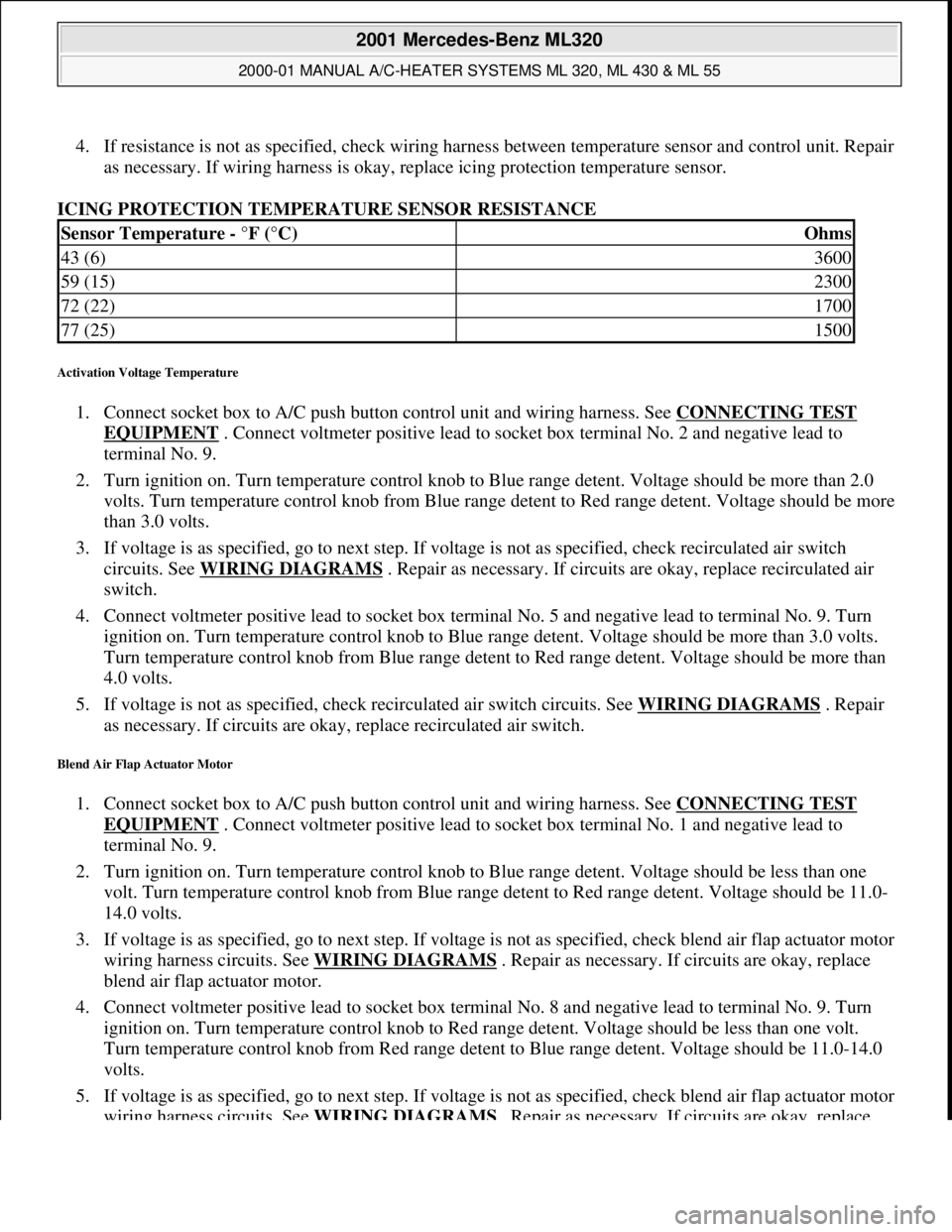
4. If resistance is not as specified, check wiring harness between temperature sensor and control unit. Repair
as necessary. If wiring harness is okay, replace icing protection temperature sensor.
ICING PROTECTION TEMPERATURE SENSOR RESISTANCE
Activation Voltage Temperature
1. Connect socket box to A/C push button control unit and wiring harness. See CONNECTING TEST
EQUIPMENT . Connect voltmeter positive lead to socket box terminal No. 2 and negative lead to
terminal No. 9.
2. Turn ignition on. Turn temperature control knob to Blue range detent. Voltage should be more than 2.0
volts. Turn temperature control knob from Blue range detent to Red range detent. Voltage should be more
than 3.0 volts.
3. If voltage is as specified, go to next step. If voltage is not as specified, check recirculated air switch
circuits. See WIRING DIAGRAMS
. Repair as necessary. If circuits are okay, replace recirculated air
switch.
4. Connect voltmeter positive lead to socket box terminal No. 5 and negative lead to terminal No. 9. Turn
ignition on. Turn temperature control knob to Blue range detent. Voltage should be more than 3.0 volts.
Turn temperature control knob from Blue range detent to Red range detent. Voltage should be more than
4.0 volts.
5. If voltage is not as specified, check recirculated air switch circuits. See WIRING DIAGRAMS
. Repair
as necessary. If circuits are okay, replace recirculated air switch.
Blend Air Flap Actuator Motor
1. Connect socket box to A/C push button control unit and wiring harness. See CONNECTING TEST
EQUIPMENT . Connect voltmeter positive lead to socket box terminal No. 1 and negative lead to
terminal No. 9.
2. Turn ignition on. Turn temperature control knob to Blue range detent. Voltage should be less than one
volt. Turn temperature control knob from Blue range detent to Red range detent. Voltage should be 11.0-
14.0 volts.
3. If voltage is as specified, go to next step. If voltage is not as specified, check blend air flap actuator motor
wiring harness circuits. See WIRING DIAGRAMS
. Repair as necessary. If circuits are okay, replace
blend air flap actuator motor.
4. Connect voltmeter positive lead to socket box terminal No. 8 and negative lead to terminal No. 9. Turn
ignition on. Turn temperature control knob to Red range detent. Voltage should be less than one volt.
Turn temperature control knob from Red range detent to Blue range detent. Voltage should be 11.0-14.0
volts.
5. If voltage is as specified, go to next step. If voltage is not as specified, check blend air flap actuator motor
wiring harness circuits. See WIRING DIAGRAMS
. Repair as necessary. If circuits are okay, replace
Sensor Temperature - °F (°C)Ohms
43 (6)3600
59 (15)2300
72 (22)1700
77 (25)1500
2001 Mercedes-Benz ML320
2000-01 MANUAL A/C-HEATER SYSTEMS ML 320, ML 430 & ML 55
me
Saturday, October 02, 2010 3:25:10 PMPage 12 © 2006 Mitchell Repair Information Company, LLC.