Page 1889 of 4133
Rear seats
Fig. 309: Identifying Torx Bit Set (000 589 01 10 00)
Fig. 310: Identifying Longitudinal Wedge (115 589 03 59 00)
Parts ordering notes
39Install glove
compartment
Remove/install glove
compartment AR68.10-P-1400GI
Torx bit setFig. 309
40Connect ground cable for
battery
Disconnect ground lead
from battery AR54.10-P-0003A
41.1Initialize DVD player As of VIN A289565,
X754620.AZ82.60-P-0004-07GH
NumberDesignationModel 163 as of 09/99
BA91.12-P-1005-03ANuts for rear seat console
on vehicle floorNM40
BA91.12-P-1008-03AScrews for rear seat
console on vehicle floorNM40
Part no.DesignationQuantity
B6 782 6500Monitor, anthracite/orion, with 2
earphones (NTSC)1
2001 Mercedes-Benz ML320
1998-2005 ACCESSORIES & BODY, CAB Electr ical System - Body - 163 Chassis
me
Saturday, October 02, 2010 3:30:12 PMPage 394 © 2006 Mitchell Repair Information Company, LLC.
Page 2042 of 4133

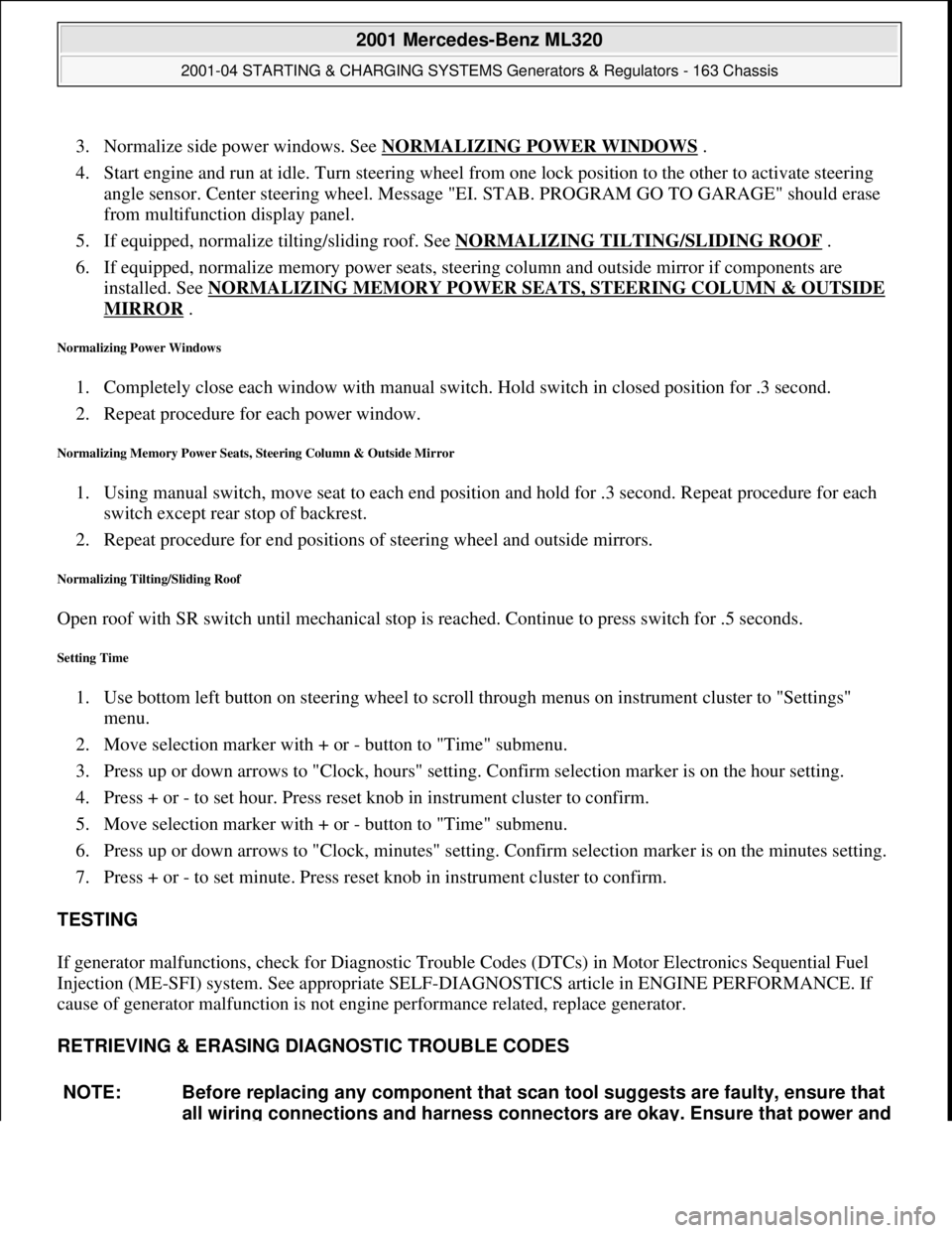
3. Normalize side power windows. See NORMALIZING POWER WINDOWS .
4. Start engine and run at idle. Turn steering wheel from one lock position to the other to activate steering
angle sensor. Center steering wheel. Message "EI. STAB. PROGRAM GO TO GARAGE" should erase
from multifunction display panel.
5. If equipped, normalize tilting/sliding roof. See NORMALIZING TILTING/SLIDING ROOF
.
6. If equipped, normalize memory power seats, steering column and outside mirror if components are
installed. See NORMALIZING MEMORY POWER SEATS, STEERING COLUMN & OUTSIDE
MIRROR .
Normalizing Power Windows
1. Completely close each window with manual switch. Hold switch in closed position for .3 second.
2. Repeat procedure for each power window.
Normalizing Memory Power Seats, Steering Column & Outside Mirror
1. Using manual switch, move seat to each end position and hold for .3 second. Repeat procedure for each
switch except rear stop of backrest.
2. Repeat procedure for end positions of steering wheel and outside mirrors.
Normalizing Tilting/Sliding Roof
Open roof with SR switch until mechanical stop is reached. Continue to press switch for .5 seconds.
Setting Time
1. Use bottom left button on steering wheel to scroll through menus on instrument cluster to "Settings"
menu.
2. Move selection marker with + or - button to "Time" submenu.
3. Press up or down arrows to "Clock, hours" setting. Confirm selection marker is on the hour setting.
4. Press + or - to set hour. Press reset knob in instrument cluster to confirm.
5. Move selection marker with + or - button to "Time" submenu.
6. Press up or down arrows to "Clock, minutes" setting. Confirm selection marker is on the minutes setting.
7. Press + or - to set minute. Press reset knob in instrument cluster to confirm.
TESTING
If generator malfunctions, check for Diagnostic Trouble Codes (DTCs) in Motor Electronics Sequential Fuel
Injection (ME-SFI) system. See appropriate SELF-DIAGNOSTICS article in ENGINE PERFORMANCE. If
cause of generator malfunction is not engine performance related, replace generator.
RETRIEVING & ERASING DIAGNOSTIC TROUBLE CODES
NOTE: Before replacing any component that scan tool suggests are faulty, ensure that
all wiring connections and harness connectors are okay. Ensure that power and
2001 Mercedes-Benz ML320
2001-04 STARTING & CHARGING SYSTEMS Generators & Regulators - 163 Chassis
me
Saturday, October 02, 2010 3:20:32 PMPage 8 © 2006 Mitchell Repair Information Company, LLC.
Page 2352 of 4133
Fig. 123: Identifying Valve Dimensions
CHECKING AND MACHINING DIMENSIONS FOR VALVE SEATS - AR05.30-P-4510-01AV
Test values for valve seat rings
965/967/968/
980/981/982/
984/987/988/
990/991/992/
993/995
BE05.30-P-
1001-01EValve disk
dia.Exhaustmm41±0,143±0,136±0,1
Intakemm36±0,138±0,133±0,1
BE05.30-P-
1002-01EValve disk
heightExhaust when
newmm1.61.61.6
Intake valve
when newmm1.21.21.1
BE05.30-P-
1003-01EValve seat
angle(aExhaust)Angle°45±15'45±15'45±15'
IntakeAngle°45±15'45±15'45±15'
BE05.30-P-
1004-01EValve stem
dia.Exhaustmm6,9706,9706,970
Intakemm6,9756,9755,975
BE05.30-P-
1005-01EValve lengthExhaustmm122,25±0,2121,80±0,2104,30 ±0,2
Intakemm119,40±0,2119,10±0,2103,60 ±0,2
NumberDesignationEngine
112.910/
911Engine 112.912/
914/915/920/
921/922/923/
940/941/942/
943/944/945/
2004 Mercedes-Benz ML350
1998-2005 ENGINE Engine timing - 163 Chassis
me
Saturday, October 02, 2010 3:39:39 PMPage 111 © 2006 Mitchell Repair Information Company, LLC.
Page 2355 of 4133

Commercially available tools
Workshop equipment
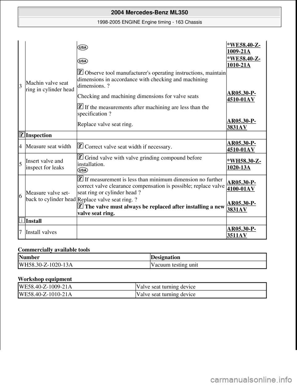
3Machin valve seat
ring in cylinder head
*WE58.40-Z-
1009-21A
*WE58.40-Z-
1010-21A
Observe tool manufacturer's operating instructions, maintain
dimensions in accordance with checking and machining
dimensions. ?
Checking and machining dime nsions for valve seatsAR05.30-P-
4510-01AV
If the measurements after machining are less than the
specification ?
Replace valve seat ring.AR05.30-P-
3831AV
Inspection
4Measure seat width Correct valve seat width if necessary.AR05.30-P-
4510-01AV
5Insert valve and
inspect for leaks Grind valve with valve grinding compound before
installation.
*WH58.30-Z-
1020-13A
6Measure valve set-
back to cylinder head
If measurement is less than minimum dimension no further
correct valve clearance compensation is possible; replace valve
seat ring or cylinder head ?AR05.30-P-
4100-01AV
Replace valve seat ring. ?
The valve must always be rep laced after installing a new
valve seat ring. AR05.30-P-
3831AV
Install
7Install valves AR05.30-P-
3511AV
NumberDesignation
WH58.30-Z-1020-13AVacuum testing unit
WE58.40-Z-1009-21AValve seat turning device
WE58.40-Z-1010-21AValve seat turning device
2004 Mercedes-Benz ML350
1998-2005 ENGINE Engine timing - 163 Chassis
me
Saturday, October 02, 2010 3:39:39 PMPage 114 © 2006 Mitchell Repair Information Company, LLC.
Page 2372 of 4133

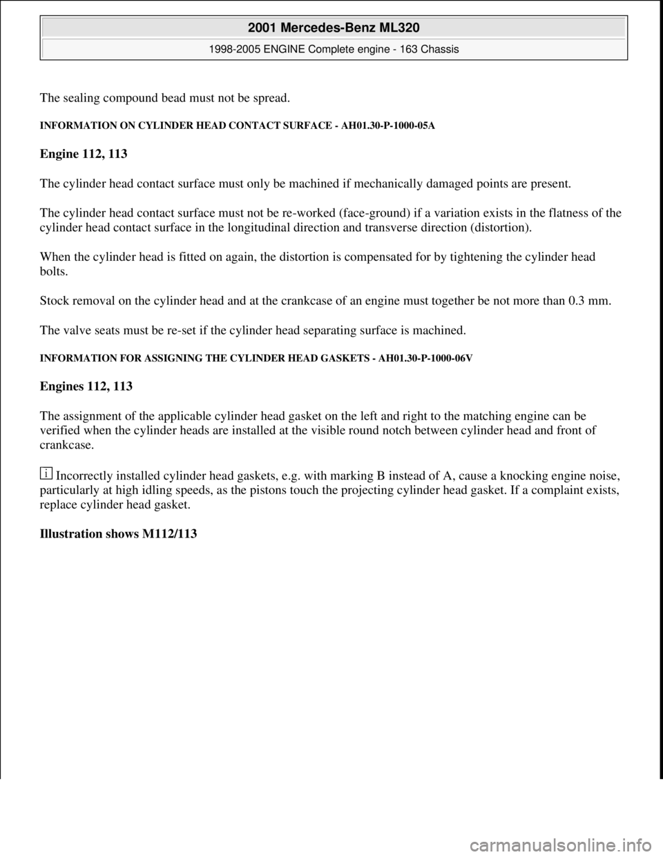
The sealing compound bead must not be spread.
INFORMATION ON CYLIND ER HEAD CONTACT SURFACE - AH01.30-P-1000-05A
Engine 112, 113
The cylinder head contact surface mu st only be machined if mechanically damaged points are present.
The cylinder head contact surface must not be re-worked (face-ground) if a variation exists in the flatness of the
cylinder head contact surface in the longitudinal direction and transverse direction (distortion).
When the cylinder head is fitted on again, the distor tion is compensated for by tightening the cylinder head
bolts.
Stock removal on the cylinder head and at the crankcase of an engine must together be not more than 0.3 mm.
The valve seats must be re-set if the cy linder head separating surface is machined.
INFORMATION FOR ASSIGNING THE CYLIND ER HEAD GASKETS - AH01.30-P-1000-06V
Engines 112, 113
The assignment of the applicable cylinder head gasket on the left and right to the matching engine can be
verified when the cylinder heads are installed at the visible round notch between cylinder head and front of
crankcase.
Incorrectly installed cylinder head gaskets, e.g. with marking B instead of A, cause a knocking engine noise,
particularly at high idling speeds, as the pistons touch the projecting cylinder head gasket. If a complaint exists,
replace cylinder head gasket.
Illustration shows M112/113
2001 Mercedes-Benz ML320
1998-2005 ENGINE Complete engine - 163 Chassis
me
Saturday, October 02, 2010 3:17:55 PMPage 16 © 2006 Mitchell Repair Information Company, LLC.
Page 2541 of 4133
Fig. 31: Identifying Front Axle Shaft Flange And Double-Row Angular Ball Bearing Components
Modification notes
7.8.00Pulling out front axle
shaft flange, changed
Step 2:
The front axle shaft flange is now pulled out using a
stationary press and not with the auxiliary hydraulic
press.
AR33.20-P-
0315-01GI
Remove/Install
1Remove steering knuckle AR33.25-P-
0400GH
2Pull out front axle shaft flange (9)
AR33.20-P-
0315-01GI
Extractor toolFig. 19
Extraction and insertion toolFig. 20
3Detach circlip (9p)
Installation: Ensure that the circlip
seats securely in the wheel carrier.
Pliers for locking ring*WH58.30-Z-
1009-02A
4Pull double-row angular ball bearing
(9n) out of steering knuckle AR33.20-P-
0315-03GH
Extraction and insertion toolFig. 20
AR33.20-P-
0315-04GH
2001 Mercedes-Benz ML320
1998-2005 DRIVELINE/AXLES Front Axle - 163 Chassis
me
Saturday, October 02, 2010 3:38:22 PMPage 22 © 2006 Mitchell Repair Information Company, LLC.
Page 2656 of 4133

CONVERSION MEASURES RESULTING IN ALTERATION TO VEHICLE MODEL - AH00.10-P-1000-01A
Model 100, 107, 108, 109, 111, 112, 113, 114, 115, 116, 123, 124, 126, 129, 140, 163, 168, 170, 201, 202, 208,
210
We disapprove of all vehicle conversions resulting in an alteration to the model. A standard production vehicle
is a design entity which, upon installation of parts alien to the model, usually changes in a detrimental way.
Changes to important components influence the homogeneity of the vehicle in its entirety. For this reason we
have not investigated the details to be observed when performing such conversions. Such conversions can also
lead to changes on the vehicle which require new proof that the vehicle complies with legal requirements.
The main reasons for our disapproval are:
1. Subsequent installation of a component such as a more powerful engine may overload the remaining
components such as the transmission, brakes, axles, etc.
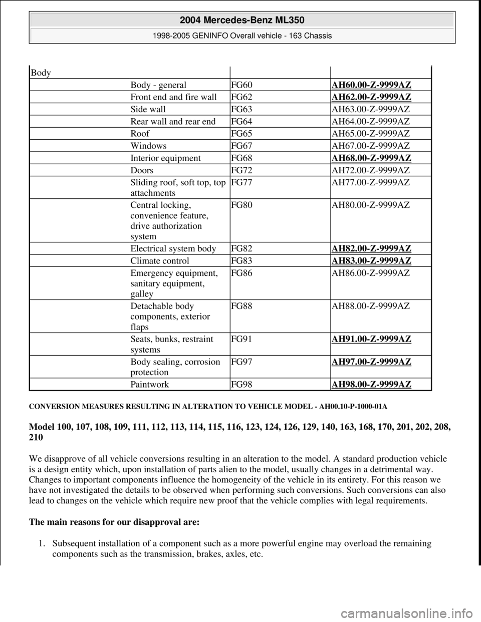
Body
Body - generalFG60AH60.00-Z-9999AZ
Front end and fire wallFG62AH62.00-Z-9999AZ
Side wallFG63AH63.00-Z-9999AZ
Rear wall and rear endFG64AH64.00-Z-9999AZ
RoofFG65AH65.00-Z-9999AZ
WindowsFG67AH67.00-Z-9999AZ
Interior equipmentFG68AH68.00-Z-9999AZ
DoorsFG72AH72.00-Z-9999AZ
Sliding roof, soft top, top
attachmentsFG77AH77.00-Z-9999AZ
Central locking,
convenience feature,
drive authorization
systemFG80AH80.00-Z-9999AZ
Electrical system bodyFG82AH82.00-Z-9999AZ
Climate controlFG83AH83.00-Z-9999AZ
Emergency equipment,
sanitary equipment,
galleyFG86AH86.00-Z-9999AZ
Detachable body
components, exterior
flapsFG88AH88.00-Z-9999AZ
Seats, bunks, restraint
systemsFG91AH91.00-Z-9999AZ
Body sealing, corrosion
protectionFG97AH97.00-Z-9999AZ
PaintworkFG98AH98.00-Z-9999AZ
2004 Mercedes-Benz ML350
1998-2005 GENINFO Overall vehicle - 163 Chassis
me
Saturday, October 02, 2010 3:47:44 PMPage 11 © 2006 Mitchell Repair Information Company, LLC.
Page 3273 of 4133
REAR FOOTWELL AIR OUTLET, LOCATION/TASK/FUNCTION - GF83.10-P-2146GI
MODEL 163 as of 1.9.01 with CODE (580a) Automatic air conditioning
Fig. 24: Identifying Left And Right Rear Compartment Air Vent
CENTER NOZZLE, LOCATION/PURPOSE/FUNCTION - GF83.10-P-2149GC
MODEL 163, 168
Rear footwell air vent taskThe rear footwell air vent is used to ventilate the rear
footwell.
Rear footwell air vent
function GF83.10-P-2110-
01GC
Rear footwell air vent
locationThe left and right rear footwell air vents (1,2) are below the
passenger and driver's seats.
Rear footwell air vent
taskThe left and right rear footwell air vents (1,2) are used to
ventilate the rear footwell.
Rear footwell air vent
function GF83.10-P-2110-
01GI
Center nozzle,
locationModel 168GF83.10-P-
2107-02GC
GF83.10-P-
2001 Mercedes-Benz ML320
1998-2005 HVAC Climate Control - 163 Chassis
me
Saturday, October 02, 2010 3:23:15 PMPage 29 © 2006 Mitchell Repair Information Company, LLC.