Page 1139 of 4133

335 Index
Seat belts 64
Cleaning 238
Fastening 42
Height adjustment 45
Proper use of 44, 66
Safety guidelines 62
Warning lamp 253
Seat heater*
Switching off 98
Switching on 98
Seats 95
Adjusting 34
Heater* 98
Manual 35
Power 37
Rapid seat heating* 98
Rear 99
Split rear bench seat 99
Securing cargo
Cargo tie-down rings 158
Selector lever 26
Lock 46
Position 26, 119Self-test
BabySmart
TM airbag deactivation
system 70
Tele Aid* 172
Service
Calling up the service indicator 233
Major service (Service B) 232
Minor service (Service A) 232
Overdue 233
Spare parts
Types 233
When due 232
Service and Warranty Booklet
Loss of 291
Service and warranty information 10
Service indicator 232
Calling up 233
Clearing 232, 233
Service indicator (FSS)
Display messages 256
Service life (tires) 227Service System see FSS
Setting
Cruise control 151
Higher speed in cruise control 152
Hours (clock) 118
Lower speed in cruise control 152
Minutes (clock) 118
Slower speed in cruise control 152
Speed in cruise control 152
Setting date
Trip computer* 186
Setting language
Trip computer* 190
Shift lock 314
Shifting
Gear selector lever positions 122
Into optimal gear range (automatic
transmission) 120
Side impact airbags 64
Side marker lamps
Replacing bulbs 266, 267, 269
Page 1142 of 4133

338 IndexTele Aid* 171
Emergency calls 173
Information 177
Initiating an emergency call
manually 175
Remote door unlock 179
Roadside assistance 175
Stolen vehicle tracking services 180
System self-check 172
Upgrade signals 178
Telematics* 315
Telephone* 170
Temperature
Grades of tires 309
Tires 228
Third row seats* 102
Folding down single seat 102
Installing single seat 104
Removing single seat 104
Storing single seat 103
Tie-down rings (Cargo
compartment) 158Tightening torque 315
Tightening torque (Wheel bolts) 277
Tilt
Head restraint 37, 39
Time
Setting hours 118
Setting minutes 118
Tire inflation pressure
Checking 216, 227
Tire speed rating 198, 315
Tire traction 197
Tires 295, 308
Direction of rotation 227
Driving instructions 196
Retreads 226
Rims and tires 295
Rotating 228
Service life 227
Temperature 228
Temperature grades 309
Tread depth 230
Wear pattern 228
Winter 230Tools 257
Vehicle jack 258
Vehicles with CD-changer* 258
Wheel bolt wrench 258
Tow-away alarm 29, 84
Arming 84
Disarming 84
Disarming for transport 84
Towing
Trailer 206
Towing a trailer 209
Automatic transmission 124
Towing eyes
Front 285
Rear 285
Towing the vehicle 283
Stranded vehicle 286
Tracking services
For stolen vehicle 180
Page 1494 of 4133

AR91.12-P-1010GI
Remove and install bench
21.3.00
MODELS
163.136 /154 /172 as of 1.9.99,
163.113 /128 /157 /174 /175
40 % bench seat
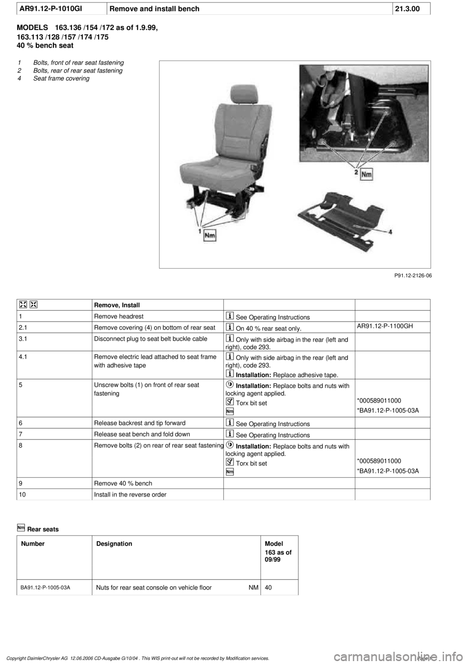
P91.12-2126-06
1
Bolts, front of rear seat fastening
2
Bolts, rear of rear seat fastening
4
Seat frame covering
Remove, Install
1
Remove headrest
See Operating Instructions
2.1
Remove covering (4) on bottom of rear seat
On 40 % rear seat only.
AR91.12-P-1100GH
3.1
Disconnect plug to seat belt buckle cable
Only with side airbag in the rear (left and
right), code 293.
4.1
Remove electric lead attached to seat frame
with adhesive tape
Only with side airbag in the rear (left and
right), code 293.
Installation:
Replace adhesive tape.
5
Unscrew bolts (1) on front of rear seat
fastening
Installation:
Replace bolts and nuts with
locking agent applied.
Torx bit set
*000589011000
*BA91.12-P-1005-03A
6
Release backrest and tip forward
See Operating Instructions
7
Release seat bench and fold down
See Operating Instructions
8
Remove bolts (2) on rear of rear seat fastening
Installation:
Replace bolts and nuts with
locking agent applied.
Torx bit set
*000589011000
*BA91.12-P-1005-03A
9
Remove 40 % bench
10
Install in the reverse order
Rear seats
Number
Designation
Model
163 as of
09/99
BA91.12-P-1005-03A
Nuts for rear seat console on vehicle floor
NM
40
Copyright DaimlerChrysler AG 12.06.2006 CD-Ausgabe G/10/04 . This WIS print-out will not be recorde
d by Modification services.
Page 1
Page 1791 of 4133
Fig. 197: Identifying Woofer Components
Front seats
Remove/install
1Unscrew screws on front
seat console *BA91.10-P-1001-01B
2Angle front seat back
until it rests against the
rear bench seat and fasten
with outer seat belt Cover the floor
covering behind the front
seat to avoid
contamination.
3.1Remove air duct at the
rear of the front seat Only as of VIN
A289565, X754620. 1
screw.
4Detach bass module
speaker connector
(H4/17x1)
5Unscrew screw (2)
6Remove bass module
speaker (H4/17)
7Install in the reverse order
NumberDesignationModel Series 163
BA91.10-P-1001-01BBolt of seating mounting
bracket to vehicle floorNm40
2001 Mercedes-Benz ML320
1998-2005 ACCESSORIES & BODY, CAB Electrical System - Body - 163 Chassis
me
Saturday, October 02, 2010 3:30:09 PMPage 296 © 2006 Mitchell Repair Information Company, LLC.
Page 1808 of 4133
Front seats
Seat belts/emergency tensioning retractors
FIBER OPTICAL CABLE (D2B) REPLACE COMPLETE (AFTER TESTING) - AR82.70-P-0005GJ
MODEL 163.113 /154 /174 #A as of 289565, 163.113 #X as of 754620, 163.128 /157 /175 with CODE (810)
Sound system
Left hand steering vehicle as
of 1.9.99.AR68.10-P-1520GI
Right-hand drive vehicle.AR68.10-P-1500GH
20Plug D2B plug from
exchange D2B wiring
harness (1) into radio
21Install radio AR82.60-P-7502EA
NumberDesignationModel Series 163
BA91.10-P-1001-01BBolt of seating mounting
bracket to vehicle floorNm40
NumberDesignation
Model 163 up to
08/99Model 163 as of
09/99
BA91.40-P-1001-
01DScrew on belt end
fittingNm3535
2001 Mercedes-Benz ML320
1998-2005 ACCESSORIES & BODY, CAB Electrical System - Body - 163 Chassis
me
Saturday, October 02, 2010 3:30:10 PMPage 313 © 2006 Mitchell Repair Information Company, LLC.
Page 1814 of 4133
![MERCEDES-BENZ ML430 1997 Complete Repair Manual Front seats
REPLACE FIBER OPTICAL CABLE (D2B) BETWEEN THE RADIO AND E-CALL CONTROL MODULE/CTEL [TEL]
INTERFACE (AFTER TESTING) - AR82.95-P-0015GH
MODEL 163.136 #A as of 051500, 163.136 #X as of 70 MERCEDES-BENZ ML430 1997 Complete Repair Manual Front seats
REPLACE FIBER OPTICAL CABLE (D2B) BETWEEN THE RADIO AND E-CALL CONTROL MODULE/CTEL [TEL]
INTERFACE (AFTER TESTING) - AR82.95-P-0015GH
MODEL 163.136 #A as of 051500, 163.136 #X as of 70](/manual-img/4/57307/w960_57307-1813.png)
Front seats
REPLACE FIBER OPTICAL CABLE (D2B) BETWEEN THE RADIO AND E-CALL CONTROL MODULE/CTEL [TEL]
INTERFACE (AFTER TESTING) - AR82.95-P-0015GH
MODEL 163.136 #A as of 051500, 163.136 #X as of 708319, 163.154 #A as of 051500, 163.154 #X as of
708319, 163.172 #A as of 051500, 163.172 #X as of 708319, 163.113/128/157/174/175 with CODE (852)
CTEL preinstallation assembly at dome with CODE (854) MB portable cellular telephone
MODEL 163.154 /172 /174 #A as of 221506, 163.157/175 with CODE (349) E Call emergency call system
with CODE (494a) USA version
1Remove fuse f8 from fuse
and relay module
2Unscrew screws on front
seat console *BA91.10-P-1001-01B
3Angle front seat back
until it rests against the
rear bench seat and fasten
with outer seat belt Remove wiring
harness for E-call speaker
from E-call bracket.
Cover the floor covering
behind the front seat to
avoid contamination.
4Detach connector (2) and
antenna plug (4) from the
E-call control module
(A35/8)
5Detach conductive
coupling D2B (3) Do not kink or stretch
fiber optic cable. Press
protective caps on
conductive coupling and
device connection.AR82.95-P-0005-01A
6Unscrew screws (5)
7Remove E-call control
module (A35/8)
8Install in the reverse order
NumberDesignationModel Series 163
BA91.10-P-1001-01BBolt of seating mounting
bracket to vehicle floorNm40
2001 Mercedes-Benz ML320
1998-2005 ACCESSORIES & BODY, CAB Electrical System - Body - 163 Chassis
me
Saturday, October 02, 2010 3:30:10 PMPage 319 © 2006 Mitchell Repair Information Company, LLC.
Page 1817 of 4133

Front seats
Seat belts/emergency tensioning retractors
MAINTENANCE
CHECK SETTING OF HIGH BEAM - AP82.10-P-8260-02A
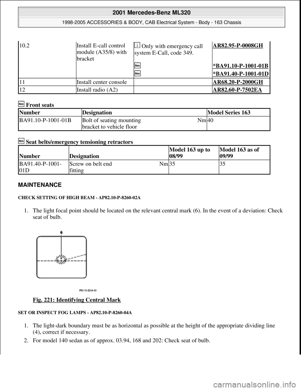
1. The light focal point should be located on the relevant central mark (6). In the event of a deviation: Check
seat of bulb.
Fig. 221: Identifying Central Mark
SET OR INSPECT FOG LAMPS - AP82.10-P-8260-04A
1. The light-dark boundary must be as horizontal as possible at the height of the appropriate dividing line
(4), correct if necessary.
2. For model 140 sedan as of approx. 03.94, 168 and 202: Check seat of bulb.
10.2Install E-call control
module (A35/8) with
bracket Only with emergency call
system E-Call, code 349.AR82.95-P-0008GH
*BA91.10-P-1001-01B
*BA91.40-P-1001-01D
11Install center console AR68.20-P-2000GH
12Install radio (A2) AR82.60-P-7502EA
NumberDesignationModel Series 163
BA91.10-P-1001-01BBolt of seating mounting
bracket to vehicle floorNm40
NumberDesignation
Model 163 up to
08/99Model 163 as of
09/99
BA91.40-P-1001-
01DScrew on belt end
fittingNm3535
2001 Mercedes-Benz ML320
1998-2005 ACCESSORIES & BODY, CAB Electrical System - Body - 163 Chassis
me
Saturday, October 02, 2010 3:30:10 PMPage 322 © 2006 Mitchell Repair Information Company, LLC.
Page 1879 of 4133
Fig. 299: Identifying Center Console, Auxiliary Interface Module And Retaining Spring
RETROFIT VIDEO PLAYER - AZ82.60-P-0004-05A
Model 163.136 /154 /172 #A as of 145273, Models 163.136 /154 /172 #X as of 708319, Models
163.113/128 /157 /174 /175
Rear seats
1. Unscrew rear nut (1) and bolt (2) from 60% rear seat.
2. Position bracket (3)and secure with bolt (2) and nut (1) .
Insert bolt with Loctite. Replace nut.
3. Install covers under the 60% rear bench.
Replace center cover at rear seat bench at bottom with cover from the conversion kit. Do NOT install
shade at front at the 60% bench.
NumberDesignationModel 163 as of 09/99
BA91.12-P-1005-03ANuts for rear seat console
on vehicle floorNM40
BA91.12-P-1008-03AScrews for rear seat
console on vehicle floorNM40
2001 Mercedes-Benz ML320
1998-2005 ACCESSORIES & BODY, CAB Electrical System - Body - 163 Chassis
me
Saturday, October 02, 2010 3:30:12 PMPage 384 © 2006 Mitchell Repair Information Company, LLC.