1997 MERCEDES-BENZ ML430 cooling
[x] Cancel search: coolingPage 3252 of 4133
Two main objectives are pursued in heating operation:
rapid heating and even control of in-car temperature
good visibility through windshield and front side windows
In the starting phase the headroom temperature is deliberately increased, in order to meet the passengers' initial
increased heat requirements. The temperature and the duration depend on the outside temperature and the in-car
temperature.
As far as good visibility is concerned, special control measures to accelerate defrosting of the windows are
taken during the starting phase, depending on the ambient conditions.
In closed-loop operation the footwell vents are mainly used to control the in-car temperature. The center nozzle
is fully closed. The defrosting control measures are reduced.
Cooling operation
During cooling operation the objective is to cool the interior rapidly and evenly control the temperature.
Window fogging is not usually a problem during maximum cooling operation and therefore does not require
special measures.
In the starting phase the headroom temperature is deliberately reduced. The temperature and the duration
depend on the outside temperature and the in-car temperature.
Furthermore, the cooling capacity can be reduced during subsequent operation since continuous partial
recirculating air operation can be achieved.
In closed-loop operation the center nozzles are mainly used to control the in-car temperature.
Bi-level operation (2-level operation)
In bi-level operation the temperature of the interior is controlled by a combination of the footwell nozzles and
the center nozzles.
The objective is to create stratification , which gives the passengers warm feet and a cooler head .
The air distribution shifts in the direction of heating or cooling operation depending on the controller status
trend.
Rear compartment ventilation
The rear compartment nozzles are supplied with temperature-controlled air by the front compartment automatic
air conditioning. The rear compartment nozzle outlet temperature can therefore not be separately controlled.
The air quantity and the air distribution are available as adjustable parameters. The passengers in the rear can
control the ventilation themselves usin
g appropriate buttons.
2001 Mercedes-Benz ML320
1998-2005 HVAC Climate Control - 163 Chassis
me
Saturday, October 02, 2010 3:23:14 PMPage 8 © 2006 Mitchell Repair Information Company, LLC.
Page 3277 of 4133
BLOWER MOTOR FUNCTION - GF83.10-P-2170-01GI
Function
The AAC push-button control module (N22) passes a control voltage of 0-6 V to the blower regulator (A32n1)
via the AC bus. Depending on the control voltage which is present, this then regulates the blower motor
(A32m1) operating voltage of 0-12 V. This facilitates blower speed control of 0-100 %.
The blower motor actuation (operating voltage) is influenced by the following factors:
Blower power setting manual or AUTO
Operating functions:
Air distribution
AC OFF mode
Residual engine heat mode (actuation limited to 5 V)
Mode status (heating, cooling)
Coolant temperature
Vehicle speed
Fresh air/recirculation flap setting
Flap positions
Terminal 15 (blower ON), starter running (blower OFF)
BLOWER MOTOR LOCATION/TASK/DESIGN/FUNCTION - GF83.10-P-2170GI
MODEL 163 as of 1.9.01 with CODE (580a) Automatic air conditioning
Blower, task
The rear blower motor (M2/1) serves to improve ventilation and cooling
in the rear.
The air that is drawn in by the blower in the evaporator housing is led to
the rear blower motor (M2/1) via air ducts.
The rear blower motor (M2/1) increases the flow of air.
Blower,
function GF83.10-P-
2168-01GI
2001 Mercedes-Benz ML320
1998-2005 HVAC Climate Control - 163 Chassis
me
Saturday, October 02, 2010 3:23:15 PMPage 33 © 2006 Mitchell Repair Information Company, LLC.
Page 3286 of 4133
Control is then carried out there as follows:
Temperature selector wheel MAX setting (full heater output)
Due to the setting of the blending air flaps, the drawn in air is routed through the heat exchanger. Heated
cooling water generally flows through this, as a result of which the passing air is heated. The temperature-
controlled air is guided into the vehicle interior via the various air outlets.
Temperature selector wheel MIN setting (no heater output)
In this setting, the blending air flaps block the route to the heat exchanger. The drawn in fresh air is guided
directly to the air outlets and therefore into the vehicle interior.
HEATER FUNCTIONAL DESCRIPTION TABLE OF CONTENTS - GF83.20-P-0998GH
MODEL 163 up to 31.8.01 except CODE (580) Air conditioning or Tempmatic for USA
Ventilation system function GF83.10-P-2000GH
Heater circuit function GF83.20-P-2003GH
Heater controls, function GF83.20-P-2004GH
Heater function GF83.20-P-0002GH
Ventilation system function GF83.10-P-2000GH
Heater circuit function GF83.20-P-2003GH
Heater controls, function GF83.20-P-2004GH
Air inlet, location/function GF83.10-P-2138GC
Air ducts, location/task/design GF83.10-P-2139GH
Blower, location/task/design/function GF83.10-P-2102GC
Series resistor group, location/task/function GF83.10-P-2161GC
Dust filter, location/task/function GF83.10-P-2142GH
Rear vent, location/task/function GF83.10-P-2143GC
Defroster vent, location/task/function GF83.10-P-2144GC
Center nozzle, location/task/function GF83.10-P-2149GC
Lateral nozzle, location/task/function GF83.10-P-2150GC
Front footwell air outlet, location/task/function GF83.10-P-2145GC
Rear footwell air outlet, location/task/function GF83.10-P-2146GC
Heating system heat exchanger, location/ purpose/function GF83.20-P-2108GC
Fresh air/recirculated air flap, location/task/ function GF83.20-P-2111GC
Fresh air/recirculated air flap actuator, location/ task/function GF83.30-P-2116GC
Blower switch, location/task/design/function GF83.25-P-2100GC
Air distribution switch, location/task/design/ function GF83.25-P-2101GH
Temperature selector wheel, location/task/ design/function GF83.25-P-2102GC
Air recirculation switch, location/task/design/ function GF83.10-P-2117GH
2001 Mercedes-Benz ML320
1998-2005 HVAC Climate Control - 163 Chassis
me
Saturday, October 02, 2010 3:23:15 PMPage 42 © 2006 Mitchell Repair Information Company, LLC.
Page 3302 of 4133
clockwise direction to the final indented position (max. cooling), the recirculation switch is bypassed and thus
the fresh air flaps closed, in order to achieve the max. interior cooling (with A/C ON).
TEMPERATURE SELECTOR WHEEL, FUNCTION - GF83.25-P-2102-01GI
Function
The desired in-car temperature is set by turning the temperature selector wheel on the AAC push-button control
module (N22).
The AAC push-button control module (N22) compares the desired temperature with the temperature in the
passenger compartment. The passenger compartment temperature is determined by the in-car temperature
sensor on the AAC push-button control module (N22) and the temperature sensor for the vent air at the center
nozzle, front and rear footwells.
Using the comparison between specified and actual values, the AAC push-button control module (N22)
determines the correct setting of the blending air flaps and actuates these. The selected temperature is reached
and maintained as quickly as possible, if warming or cooling of the interior is necessary.
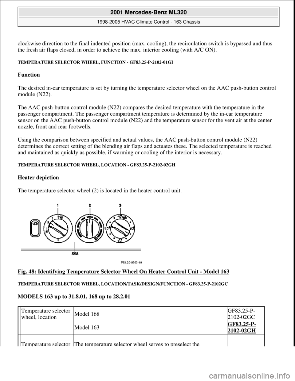
TEMPERATURE SELECTOR WHEEL, LOCATION - GF83.25-P-2102-02GH
Heater depiction
The temperature selector wheel (2) is located in the heater control unit.
Fig. 48: Identifying Temperature Selector Wheel On Heater Control Unit
- Model 163
TEMPERATURE SELECTOR WHEEL, LOCATION/TASK/DESIGN/FUNCTION - GF83.25-P-2102GC
MODELS 163 up to 31.8.01, 168 up to 28.2.01
Temperature selector
wheel, locationModel 168GF83.25-P-
2102-02GC
Model 163GF83.25-P-
2102-02GH
Temperature selector The temperature selector wheel serves to preselect the
2001 Mercedes-Benz ML320
1998-2005 HVAC Climate Control - 163 Chassis
me
Saturday, October 02, 2010 3:23:15 PMPage 58 © 2006 Mitchell Repair Information Company, LLC.
Page 3303 of 4133
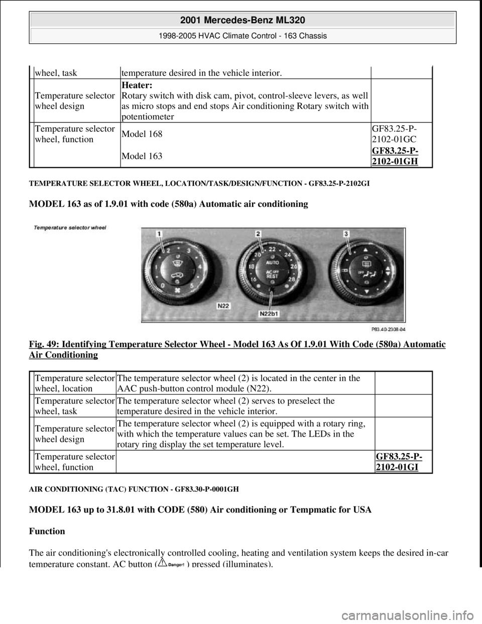
TEMPERATURE SELECTOR WHEEL, LOCATION/TASK/DESIGN/FUNCTION - GF83.25-P-2102GI
MODEL 163 as of 1.9.01 with code (580a) Automatic air conditioning
Fig. 49: Identifying Temperature Selector Wheel
- Model 163 As Of 1.9.01 With Code (580a) Automatic
Air Conditioning
AIR CONDITIONING (TAC) FUNCTION - GF83.30-P-0001GH
MODEL 163 up to 31.8.01 with CODE (580) Air conditioning or Tempmatic for USA
Function
The air conditioning's electronically controlled cooling, heating and ventilation system keeps the desired in-car
temperature constant. AC button ( ) pressed (illuminates).
wheel, tasktemperature desired in the vehicle interior.
Temperature selector
wheel design
Heater:
Rotary switch with disk cam, pivot, control-sleeve levers, as well
as micro stops and end stops Air conditioning Rotary switch with
potentiometer
Temperature selector
wheel, functionModel 168GF83.25-P-
2102-01GC
Model 163GF83.25-P-
2102-01GH
Temperature selector
wheel, locationThe temperature selector wheel (2) is located in the center in the
AAC push-button control module (N22).
Temperature selector
wheel, taskThe temperature selector wheel (2) serves to preselect the
temperature desired in the vehicle interior.
Temperature selector
wheel designThe temperature selector wheel (2) is equipped with a rotary ring,
with which the temperature values can be set. The LEDs in the
rotary ring display the set temperature level.
Temperature selector
wheel, function GF83.25-P-
2102-01GI
2001 Mercedes-Benz ML320
1998-2005 HVAC Climate Control - 163 Chassis
me
Saturday, October 02, 2010 3:23:15 PMPage 59 © 2006 Mitchell Repair Information Company, LLC.
Page 3304 of 4133
After starting, the refrigerant compressor starts up. If cooling is not necessary, the refrigerant compressor's
output is lowered and switched off via the icing inhibitor.
The air conditioning is always ready for operation after the engine has been started, and operates according to
the so-called "reheat" principle. This means: The refrigerant compressor always operates at an ambient
temperature in excess of 1°C, therefore also cools cold incoming air. Following the cooling process, the dried
air is heated at the heat exchanger.
On the one hand, this effect serves the purpose of comfort, because cooling also simultaneously causes air
dehumidification which, in turn, is an important prerequisite for a pleasant interior climate. On the other hand,
the air is dried as a result of this cooling and heating, thereby preventing window fogging.
Pressing the AC button again ( ) (does not illuminate) switches off the cooling.
Heating mode
The in-car temperature sensor measures the air temperature in the interior of the vehicle.
The air conditioning control module electronics compares the in-car temperature with the desired temperature
which has been set at the temperature selector wheels.
The microprocessor adjusts the air conditioning electronics or keeps the relevant setting constant as required.
Heater operation with heater booster in vehicles with engine 612.963 as of 12/99
In vehicles equipped with direct-injection diesel engines, an electrical heater booster is additionally installed in
the evaporator housing downstream of the heat exchanger, in order to compensate any heater output deficit
which exists under certain operating conditions.
The 3 heating elements in the heater booster are supplied with current, whereupon they are heated and they start
to glow. As a result of the structural conditions, it is ensured that the drawn in fresh air flows directly past the
electric heater booster, and is therefore heated.
Cooling mode
The icing inhibitor measures the temperature at the evaporator air outlet, while the interior temperature sensor
determines the relevant in-car temperature.
The air conditioning control module electronics compares the various measured values with the desired
temperature which has been set at the temperature selector wheels.
The microprocessor adjusts the air conditioning or keeps the relevant setting constant as required.
In-car temperature sensor replaced by new typeas of 1.12.99BT83.57-P-0001-04GH
Ventilation, function GF83.10-P-2000GH
Heater circuit function GF83.20-P-2003GH
2001 Mercedes-Benz ML320
1998-2005 HVAC Climate Control - 163 Chassis
me
Saturday, October 02, 2010 3:23:15 PMPage 60 © 2006 Mitchell Repair Information Company, LLC.
Page 3309 of 4133
TABLE OF CONTENTS, AIR CONDITIONING (TAC) FUNCTION DESCRIPTION - GF83.30-P-0999GH
MODEL 163 up to 31.8.01 with code (580) Air conditioning or Tempmatic for USA
AIR CONDITIONING CONTROL MODULE FUNCTION - GF83.30-P-2001GH
MODEL 163 up to 31.8.01 with CODE (580) Air conditioning or Tempmatic for USA
The following components are integrated into the air conditioning control module (S98):
Blower switch (1): with 0 setting and 4 levels.
The blower switch (1) is not available as an individual part.
Temperature selector wheel (2): with the "Blue", non-heating setting and the continuously variable heater
setting.
When set to the indented position "blue" 100 % recirculated air is provided.
Air distribution switch (3): with the settings: Defroster vents, footwell, center plane and intermediate settings.
Recirculation switch ( ) : 100 % recirculation without time limit, when diode illuminates.
AC button ( ): Diode illuminates,
Refrigerant compressor ON cooling mode/air dehumidification Diode is not illuminated, refrigerant compressor
OFF no air dehumidification/coolin
g mode
Air conditioning (TAC) function GF83.30-P-0001GH
Ventilation system function GF83.10-P-2000GH
Heater circuit function GF83.20-P-2003GH
Air conditioning control unit function GF83.30-P-2001GH
Refrigerant circuit function GF83.40-P-2001GH
Temperature control, function GF83.57-P-2000GH
Heater booster, functionEngine 612.963GF83.70-P-0005GH
Starting heater operation, functionEngine 612.963GF83.70-P-2000GH
Terminate heater operation functionEngine 612.963GF83.70-P-2002GH
Regulate heater operation, functionEngine 612.963GF83.70-P-2004GH
Cancel heater operation, functionEngine 612.963GF83.70-P-2005GH
Air conditioning, location of components GF83.30-P-0003-01GH
2001 Mercedes-Benz ML320
1998-2005 HVAC Climate Control - 163 Chassis
me
Saturday, October 02, 2010 3:23:15 PMPage 65 © 2006 Mitchell Repair Information Company, LLC.
Page 3311 of 4133
AC CONTROL MODULE LOCATION/TASK/FUNCTION - GF83.30-P-2102GH
MODEL 163 up to 31.8.01 with CODE (580) Air conditioning or Tempmatic for USA
AC BUTTON, FUNCTION - GF83.30-P-2103-01GH
Function
Pressing the AC button ( ) switches on the cooling mode.
AC button ( ) pressed
Diode is illuminated, cooling mode/air dehumidification, refrigerant compressor ON
AC button ( ) not depressed
Diode not illuminated, no air dehumidification/no cooling mode, refrigerant compressor OFF
The AC button ( ) is connected to the A/C control module, which regulates the refrigerant compressor
through the all-activity module. The refrigerant compressor is only active when the engine is running and the
blower switched on. To be able to determine the cut-in point for the electromagnetic coupling on the refrigerant
compressor, the all-activity module must receive additional data from the CAN bus, such as, e.g. the engine
speed.
AC BUTTON, LOCATION - GF83.30-P-2103-02GH
The AC button ( ) is located in the air conditioning control module (S98).
Air conditioning
control module,
location
GF83.30-P-
2102-02GH
Air conditioning
control module,
task
Control of air conditioning
Recording input signals of various components
Internal processing of input signals
Sending of control signals to various components
Air conditioning
control module,
function
The AC control module records the input signals of various
components, in order to check the preconditions for proper and intended
operation. It sends control signals to the following components:
Blending air flap actuator motor, fresh air/recirculated air flap actuator
motor, All-activity module.
The air conditioning (tempmatic) control module (TAC) receives input
data from the following devices: AC button, in-car temperature sensor,
temperature selector wheel, blower switch, icing protection temperature
switch, blending air flap position signal.
2001 Mercedes-Benz ML320
1998-2005 HVAC Climate Control - 163 Chassis
me
Saturday, October 02, 2010 3:23:15 PMPage 67 © 2006 Mitchell Repair Information Company, LLC.