1997 MERCEDES-BENZ ML430 cooling
[x] Cancel search: coolingPage 3357 of 4133
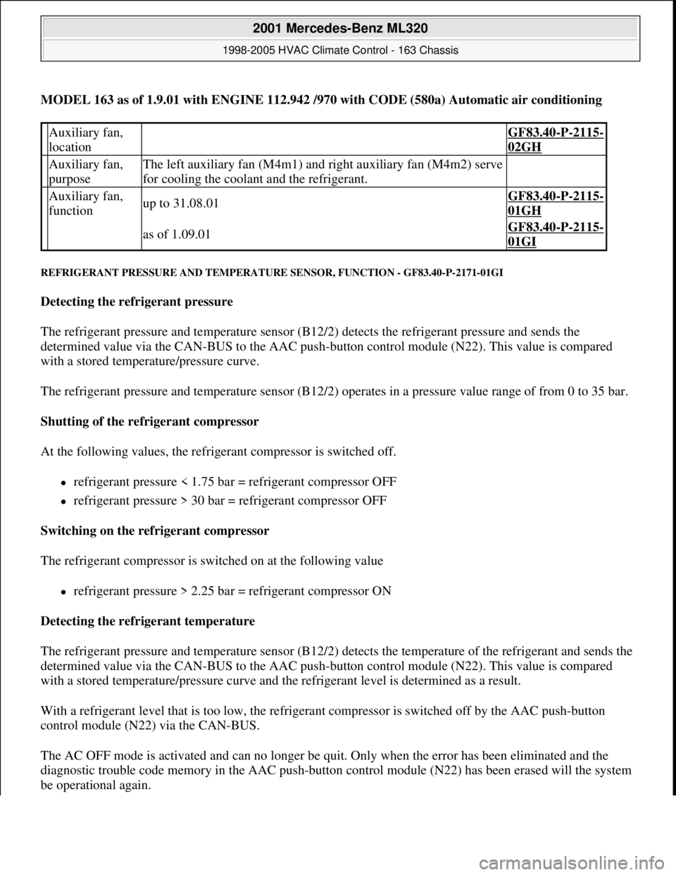
MODEL 163 as of 1.9.01 with ENGINE 112.942 /970 with CODE (580a) Automatic air conditioning
REFRIGERANT PRESSURE AND TEMPERATURE SENSOR, FUNCTION - GF83.40-P-2171-01GI
Detecting the refrigerant pressure
The refrigerant pressure and temperature sensor (B12/2) detects the refrigerant pressure and sends the
determined value via the CAN-BUS to the AAC push-button control module (N22). This value is compared
with a stored temperature/pressure curve.
The refrigerant pressure and temperature sensor (B12/2) operates in a pressure value range of from 0 to 35 bar.
Shutting of the refrigerant compressor
At the following values, the refrigerant compressor is switched off.
refrigerant pressure < 1.75 bar = refrigerant compressor OFF
refrigerant pressure > 30 bar = refrigerant compressor OFF
Switching on the refrigerant compressor
The refrigerant compressor is switched on at the following value
refrigerant pressure > 2.25 bar = refrigerant compressor ON
Detecting the refrigerant temperature
The refrigerant pressure and temperature sensor (B12/2) detects the temperature of the refrigerant and sends the
determined value via the CAN-BUS to the AAC push-button control module (N22). This value is compared
with a stored temperature/pressure curve and the refrigerant level is determined as a result.
With a refrigerant level that is too low, the refrigerant compressor is switched off by the AAC push-button
control module (N22) via the CAN-BUS.
The AC OFF mode is activated and can no longer be quit. Only when the error has been eliminated and the
diagnostic trouble code memory in the AAC push-button control module (N22) has been erased will the system
be operational again.
Auxiliary fan,
location GF83.40-P-2115-
02GH
Auxiliary fan,
purposeThe left auxiliary fan (M4m1) and right auxiliary fan (M4m2) serve
for cooling the coolant and the refrigerant.
Auxiliary fan,
functionup to 31.08.01GF83.40-P-2115-
01GH
as of 1.09.01GF83.40-P-2115-
01GI
2001 Mercedes-Benz ML320
1998-2005 HVAC Climate Control - 163 Chassis
me
Saturday, October 02, 2010 3:23:16 PMPage 113 © 2006 Mitchell Repair Information Company, LLC.
Page 3365 of 4133
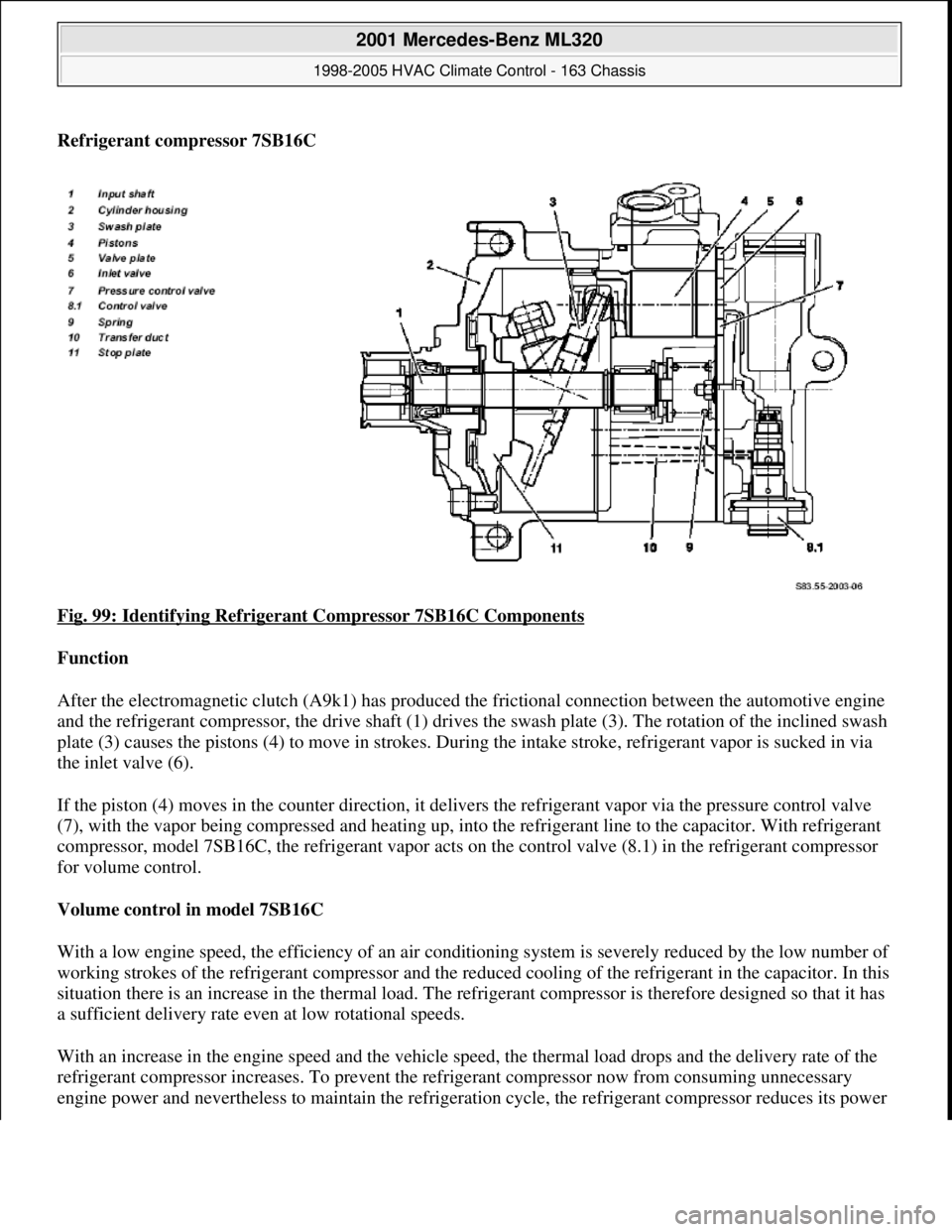
Refrigerant compressor 7SB16C
Fig. 99: Identifying Refrigerant Compressor 7SB16C Components
Function
After the electromagnetic clutch (A9k1) has produced the frictional connection between the automotive engine
and the refrigerant compressor, the drive shaft (1) drives the swash plate (3). The rotation of the inclined swash
plate (3) causes the pistons (4) to move in strokes. During the intake stroke, refrigerant vapor is sucked in via
the inlet valve (6).
If the piston (4) moves in the counter direction, it delivers the refrigerant vapor via the pressure control valve
(7), with the vapor being compressed and heating up, into the refrigerant line to the capacitor. With refrigerant
compressor, model 7SB16C, the refrigerant vapor acts on the control valve (8.1) in the refrigerant compressor
for volume control.
Volume control in model 7SB16C
With a low engine speed, the efficiency of an air conditioning system is severely reduced by the low number of
working strokes of the refrigerant compressor and the reduced cooling of the refrigerant in the capacitor. In this
situation there is an increase in the thermal load. The refrigerant compressor is therefore designed so that it has
a sufficient delivery rate even at low rotational speeds.
With an increase in the engine speed and the vehicle speed, the thermal load drops and the delivery rate of the
refrigerant compressor increases. To prevent the refrigerant compressor now from consuming unnecessary
en
gine power and nevertheless to maintain the refrigeration cycle, the refrigerant compressor reduces its power
2001 Mercedes-Benz ML320
1998-2005 HVAC Climate Control - 163 Chassis
me
Saturday, October 02, 2010 3:23:16 PMPage 121 © 2006 Mitchell Repair Information Company, LLC.
Page 3375 of 4133
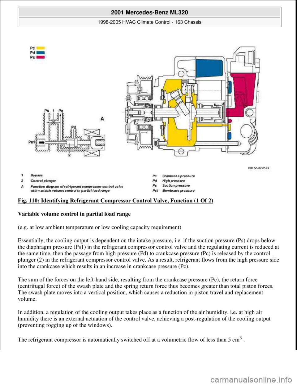
Fig. 110: Identifying Refrigerant Compressor Control Valve, Function (1 Of 2)
Variable volume control in partial load range
(e.g. at low ambient temperature or low cooling capacity requirement)
Essentially, the cooling output is dependent on the intake pressure, i.e. if the suction pressure (Ps) drops below
the diaphragm pressure (Ps1) in the refrigerant compressor control valve and the regulating current is reduced at
the same time, then the passage from high pressure (Pd) to crankcase pressure (Pc) is released by the control
plunger (2) in the refrigerant compressor control valve. As a result, refrigerant flows from the high pressure side
into the crankcase which results in an increase in crankcase pressure (Pc).
The sum of the forces on the left-hand side, resulting from the crankcase pressure (Pc), the return force
(centrifugal force) of the swash plate and the spring return force thus becomes greater than total piston forces.
The swash plate moves into a vertical position, which causes a reduction in piston travel and replacement
volume.
In addition, a regulation of the cooling output takes place as a function of the air humidity, i.e. at high air
humidity there is an external actuation of the control valve, achieving a post-regulation of the cooling output
(preventing fogging up of the windows).
The refrigerant compressor is automatically switched off at a volumetric flow of less than 5 cm
3.
2001 Mercedes-Benz ML320
1998-2005 HVAC Climate Control - 163 Chassis
me
Saturday, October 02, 2010 3:23:16 PMPage 131 © 2006 Mitchell Repair Information Company, LLC.
Page 3376 of 4133
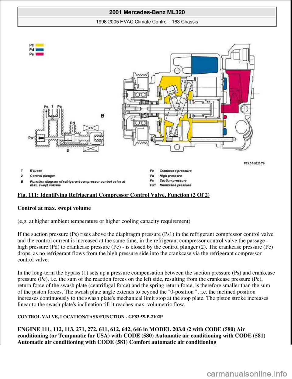
Fig. 111: Identifying Refrigerant Compressor Control Valve, Function (2 Of 2)
Control at max. swept volume
(e.g. at higher ambient temperature or higher cooling capacity requirement)
If the suction pressure (Ps) rises above the diaphragm pressure (Ps1) in the refrigerant compressor control valve
and the control current is increased at the same time, in the refrigerant compressor control valve the passage -
high pressure (Pd) to crankcase pressure (Pc) - is closed by the control plunger (2). The crankcase pressure (Pc)
drops, as no refrigerant flows from the high pressure side into the crankcase via the refrigerant compressor
control valve.
In the long-term the bypass (1) sets up a pressure compensation between the suction pressure (Ps) and crankcase
pressure (Pc), i.e. the sum of the reaction forces on the left side, resulting from the crankcase pressure (Pc),
return force of the swash plate (centrifugal force) and the spring return force, is therefore smaller than the sum
of the piston forces. The swash plate angle extends to beyond the "0-position ", i.e. the inclined position
increases continuously to the swash plate's mechanical limit stop at the stop plate. The piston stroke increases
linear to the swash plate's inclination till it reaches max. volumetric flow.
CONTROL VALVE, LOCATION/TASK/FUNCTION - GF83.55-P-2102P
ENGINE 111, 112, 113, 271, 272, 611, 612, 642, 646 in MODEL 203.0 /2 with CODE (580) Air
conditioning (or Tempmatic for USA) with CODE (580) Automatic air conditioning with CODE (581)
Automatic air conditioning with CODE (581) Comfort automatic air conditioning
2001 Mercedes-Benz ML320
1998-2005 HVAC Climate Control - 163 Chassis
me
Saturday, October 02, 2010 3:23:17 PMPage 132 © 2006 Mitchell Repair Information Company, LLC.
Page 3381 of 4133
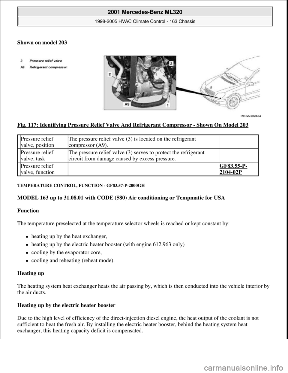
Shown on model 203
Fig. 117: Identifying Pressure Relief Valve And Refrigerant Compressor
- Shown On Model 203
TEMPERATURE CONTROL, FUNCTION - GF83.57-P-2000GH
MODEL 163 up to 31.08.01 with CODE (580) Air conditioning or Tempmatic for USA
Function
The temperature preselected at the temperature selector wheels is reached or kept constant by:
heating up by the heat exchanger,
heating up by the electric heater booster (with engine 612.963 only)
cooling by the evaporator core,
cooling and reheating (reheat mode).
Heating up
The heating system heat exchanger heats the air passing by, which is then conducted into the vehicle interior by
the air ducts.
Heating up by the electric heater booster
Due to the high level of efficiency of the direct-injection diesel engine, the heat output of the coolant is not
sufficient to heat the fresh air. By installing the electric heater booster, behind the heating system heat
exchanger, this heating capacity deficit is compensated.
Pressure relief
valve, positionThe pressure relief valve (3) is located on the refrigerant
compressor (A9).
Pressure relief
valve, taskThe pressure relief valve (3) serves to protect the refrigerant
circuit from damage caused by excess pressure.
Pressure relief
valve, function GF83.55-P-
2104-02P
2001 Mercedes-Benz ML320
1998-2005 HVAC Climate Control - 163 Chassis
me
Saturday, October 02, 2010 3:23:17 PMPage 137 © 2006 Mitchell Repair Information Company, LLC.
Page 3382 of 4133
Cooling down
The thermostatic expansion valve located on the evaporator core serves to expand the liquid refrigerant which is
under high pressure thus lowering its pressure. After this the refrigerant evaporates. The evaporation heat
required for this is taken from the air flowing through the evaporator. The resulting cooled down air then
succeeds in entering the passenger compartment via the air ducts.
Reheat mode
The air which has been cooled down and dehumidified by the evaporator core is heated up again by the heat
exchanger (reheat). This serves to prevent the windows from misting up on the inside.
Temperature selector wheel, location/task/
design/function GF83.25-P-
2102GC
Heating system heat exchanger, location/
purpose/function GF83.20-P-
2108GC
Evaporator, location/purpose/design/function GF83.40-P-
2121GC
Expansion valve, location/task/design/function GF83.40-P-
2123GC
Refrigerant compressor, location/task/design/ function GF83.55-P-
2100GH
In-car temperature sensor, location/task/functionwith suction jet nozzle up to
30.11.99GF83.57-P-
2115GH
In-car temperature sensor with ventilation fan,
location/task/functionas of 01.12.99GF83.57-P-
2107GH
Defroster protection temperature sensor,
location/task/function GF83.57-P-
2113GH
Blending air flap actuator, location / task / function GF83.57-P-
2112GC
Outside temperature sensor, location/task/ functionas of 01.12.99GF83.57-P-
2110GH
Air conditioning control module, location/task/ function GF83.30-P-
2102GH
All Activity Module, location/task/function GF54.21-P-
4110GH
Electric heater booster position/task/design/ function Engine 612.963GF83.70-P-
4054GH
Temperature regulator microswitch, location/
task/function Engine 612.963GF83.70-P-
4055GH
Extended activity module, position/task GF54.21-P-
4106GH
Extended Activity Module, location/task/designas of 1.12.99GF54.21-P-
4107GK
2001 Mercedes-Benz ML320
1998-2005 HVAC Climate Control - 163 Chassis
me
Saturday, October 02, 2010 3:23:17 PMPage 138 © 2006 Mitchell Repair Information Company, LLC.
Page 3383 of 4133
TEMPERATURE CONTROL, FUNCTION - GF83.57-P-2000GI
MODEL 163 as of 01.09.01 with CODE (580a) Automatic air conditioning
Function
The electronically controlled cooling, heating and ventilation system of the automatic air conditioning achieves
the desired in-car temperature as rapidly as possible or maintains it constantly.
The following options are available for this purpose:
the evaporator cooling the air
the heating system heat exchanger heating the air
Temperature control
The temperature values needed for the temperature control are determined by the in-car temperature sensors
(N22b1), center nozzle air stream (B10/24), footwell at front (B10/25), rear (B10/7), outside temperature
indicator (B14) and defroster protection (R35).
The electronics of the AAC push-button control module (N22) compare the various test values with the
temperature preselected at the temperature selector wheel.
As required, the automatic air conditioning performs the regulation in that in heating mode it controls the
position of the blending air flaps, via the blending air flap actuator motor (M2/6), or in cooling mode it actuates
the refrigerant compressor and thus keeps the respective setting constant.
CDI control module, location/task/function Engine 612.963GF07.16-P-
3102IA
Temperature selector wheel, location/task/ design/function GF83.25-P-
2102GI
Heating system heat exchanger, location/ purpose/function GF83.20-P-
2108GC
Evaporator, location/purpose/design/function GF83.40-P-
2121GC
Expansion valve, location/task/design/function GF83.40-P-
2123GC
Refrigerant compressor, location/task/design/ function GF83.55-P-2100P
Control valve, location/task/function GF83.55-P-2102P
In-car temperature sensor, location/task/function GF83.57-P-
2115GI
Center nozzle air stream temperature sensor,
location/task/function GF83.57-P-
2116GI
Front footwell air stream temperature sensor, GF83.57-P-
2001 Mercedes-Benz ML320
1998-2005 HVAC Climate Control - 163 Chassis
me
Saturday, October 02, 2010 3:23:17 PMPage 139 © 2006 Mitchell Repair Information Company, LLC.
Page 3398 of 4133
ultimately cause the system to burst. For this reason, all welding and soldering operations on or near closed
air conditioning systems are prohibited. High pressure levels can combine with refrigerant vapors to produce a
mixture that is potentially explosive when exposed to atmospheric air.
Risk of poisoning
Refrigerant can decompose when overheated. The resulting substances are toxic and should never be inhaled.
Risk of injury
Refrigerant vapors are heavier than air; this means that escaping gases pose a risk of suffocation for anyone in a
work pit beneath the vehicle.
Contact with liquid refrigerant may cause chilblain-like damage to the skin (due to under-cooling).
Safety instructions/precautions
All welding, brazing and soldering operations on sealed air conditioning systems and in their
immediate vicinity are prohibited.
Never smoke when working with refrigerant, never expose refrigerant to open flames.
A piercing odor can indicate overheated refrigerant - never inhale these vapors. Leave closed rooms
immediately and ventilate thoroughly.
All refrigerant must be evacuated from the entire air conditioning system prior to doing any repair work
on the air conditioning circuit or components.
Because it poses a hazard to the atmosphere as well as to personal health and safety, discharging
refrigerant directly into the air is prohibited.
Suitable evacuation, treatment and charging devices equipped with integral disposal and treatment
facilities must be used for evacuating refrigerant.
Even after the system has been evacuated, residual pressure may still be present in the system when
loosening couplings. Therefore, loosen the couplings carefully, so that the pressure can dissipate slowly.
Avoid all contact with liquid refrigerant.
Always wear safety glasses and protective gloves when working with refrigerant.
First aid measures
In case of eye contact
Immediately flush with plenty of running water and consult a physician.
In case of skin contact
Consult a physician immediately in case of frostbite. In case of inhalation
of concentrated refrigerant, immediately take victim out into the fresh air and keep victim calm.
2001 Mercedes-Benz ML320
1998-2005 HVAC Climate Control - 163 Chassis
me
Saturday, October 02, 2010 3:23:17 PMPage 154 © 2006 Mitchell Repair Information Company, LLC.