Page 3329 of 4133
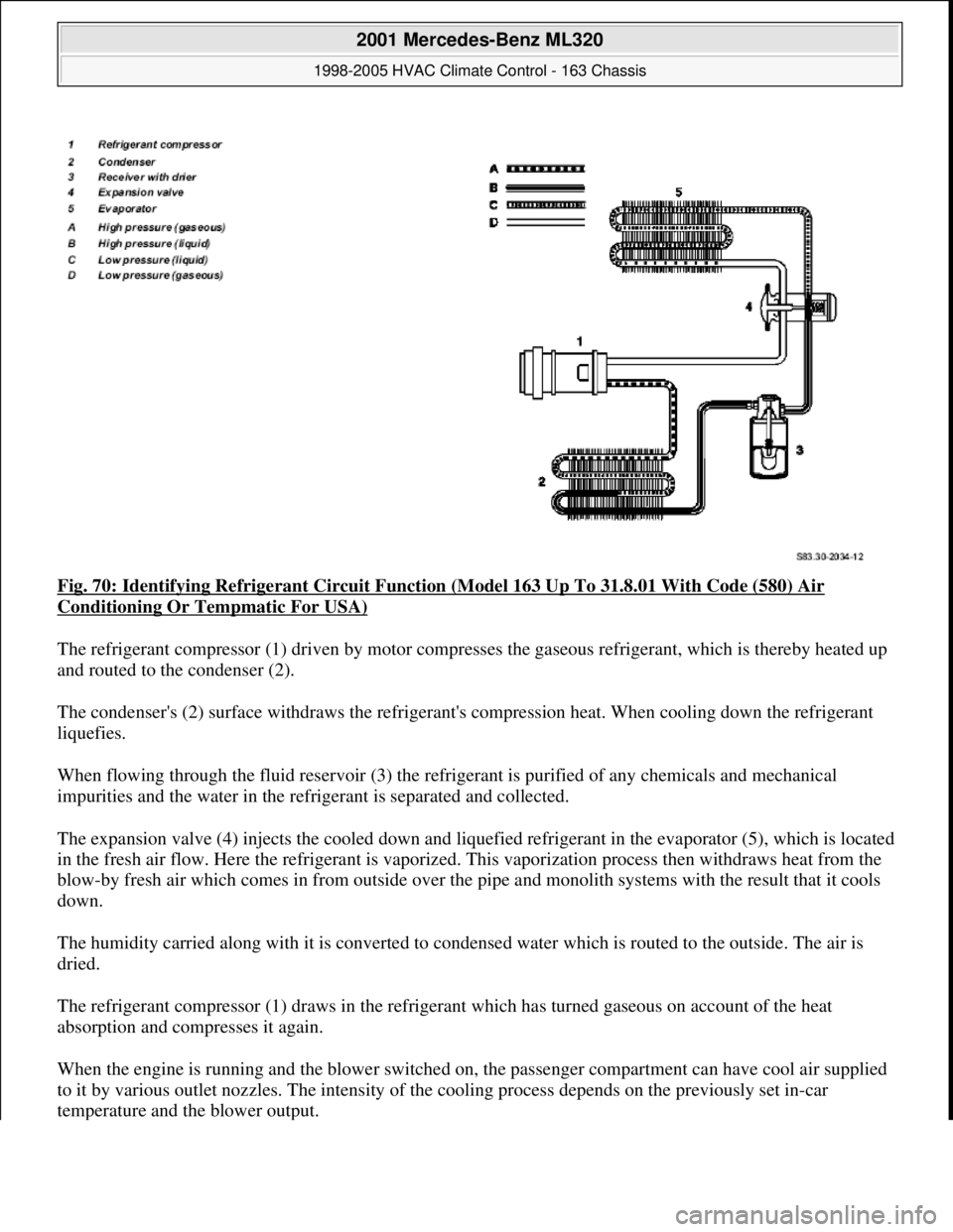
Fig. 70: Identifying Refrigerant Circuit Function (Model 163 Up To 31.8.01 With Code (580) Air
Conditioning Or Tempmatic For USA)
The refrigerant compressor (1) driven by motor compresses the gaseous refrigerant, which is thereby heated up
and routed to the condenser (2).
The condenser's (2) surface withdraws the refrigerant's compression heat. When cooling down the refrigerant
liquefies.
When flowing through the fluid reservoir (3) the refrigerant is purified of any chemicals and mechanical
impurities and the water in the refrigerant is separated and collected.
The expansion valve (4) injects the cooled down and liquefied refrigerant in the evaporator (5), which is located
in the fresh air flow. Here the refrigerant is vaporized. This vaporization process then withdraws heat from the
blow-by fresh air which comes in from outside over the pipe and monolith systems with the result that it cools
down.
The humidity carried along with it is converted to condensed water which is routed to the outside. The air is
dried.
The refrigerant compressor (1) draws in the refrigerant which has turned gaseous on account of the heat
absorption and compresses it again.
When the engine is running and the blower switched on, the passenger compartment can have cool air supplied
to it by various outlet nozzles. The intensity of the cooling process depends on the previously set in-car
temperature and the blower output.
2001 Mercedes-Benz ML320
1998-2005 HVAC Climate Control - 163 Chassis
me
Saturday, October 02, 2010 3:23:16 PMPage 85 © 2006 Mitchell Repair Information Company, LLC.
Page 3331 of 4133
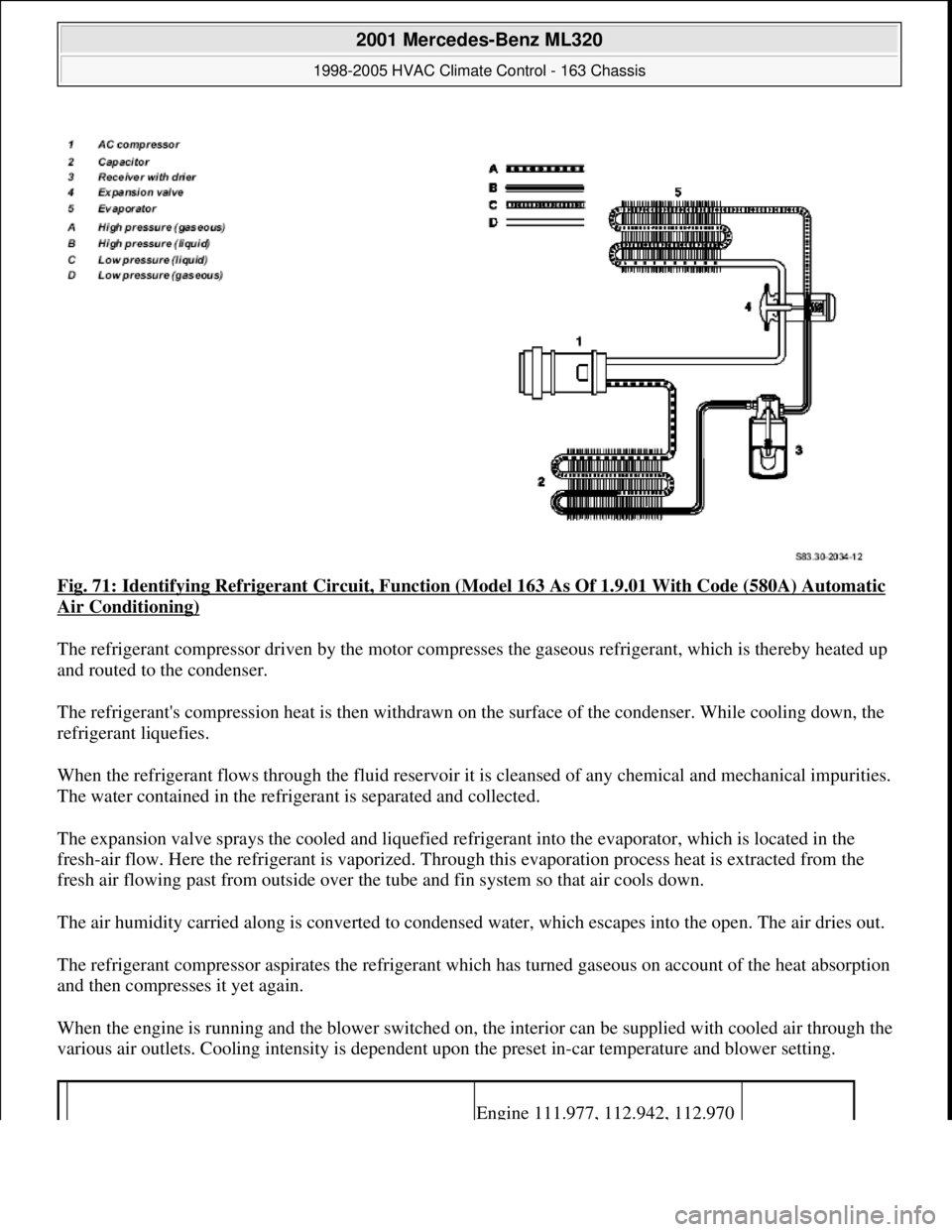
Fig. 71: Identifying Refrigerant Circuit, Function (Model 163 As Of 1.9.01 With Code (580A) Automatic
Air Conditioning)
The refrigerant compressor driven by the motor compresses the gaseous refrigerant, which is thereby heated up
and routed to the condenser.
The refrigerant's compression heat is then withdrawn on the surface of the condenser. While cooling down, the
refrigerant liquefies.
When the refrigerant flows through the fluid reservoir it is cleansed of any chemical and mechanical impurities.
The water contained in the refrigerant is separated and collected.
The expansion valve sprays the cooled and liquefied refrigerant into the evaporator, which is located in the
fresh-air flow. Here the refrigerant is vaporized. Through this evaporation process heat is extracted from the
fresh air flowing past from outside over the tube and fin system so that air cools down.
The air humidity carried along is converted to condensed water, which escapes into the open. The air dries out.
The refrigerant compressor aspirates the refrigerant which has turned gaseous on account of the heat absorption
and then compresses it yet again.
When the engine is running and the blower switched on, the interior can be supplied with cooled air through the
various air outlets. Cooling intensity is dependent upon the preset in-car temperature and blower setting.
Engine 111.977, 112.942, 112.970
2001 Mercedes-Benz ML320
1998-2005 HVAC Climate Control - 163 Chassis
me
Saturday, October 02, 2010 3:23:16 PMPage 87 © 2006 Mitchell Repair Information Company, LLC.
Page 3335 of 4133
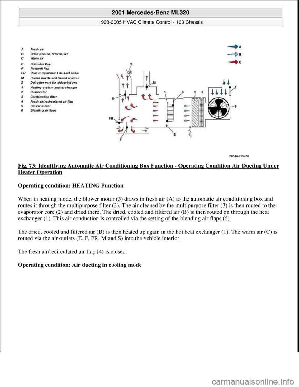
Fig. 73: Identifying Automatic Air Conditioning Box Function - Operating Condition Air Ducting Under
Heater Operation
Operating condition: HEATING Function
When in heating mode, the blower motor (5) draws in fresh air (A) to the automatic air conditioning box and
routes it through the multipurpose filter (3). The air cleaned by the multipurpose filter (3) is then routed to the
evaporator core (2) and dried there. The dried, cooled and filtered air (B) is then routed on through the heat
exchanger (1). This air conduction is controlled via the setting of the blending air flaps (6).
The dried, cooled and filtered air (B) is then heated up again in the hot heat exchanger (1). The warm air (C) is
routed via the air outlets (E, F, FR, M and S) into the vehicle interior.
The fresh air/recirculated air flap (4) is closed.
Operating condition: Air ducting in cooling mode
2001 Mercedes-Benz ML320
1998-2005 HVAC Climate Control - 163 Chassis
me
Saturday, October 02, 2010 3:23:16 PMPage 91 © 2006 Mitchell Repair Information Company, LLC.
Page 3336 of 4133
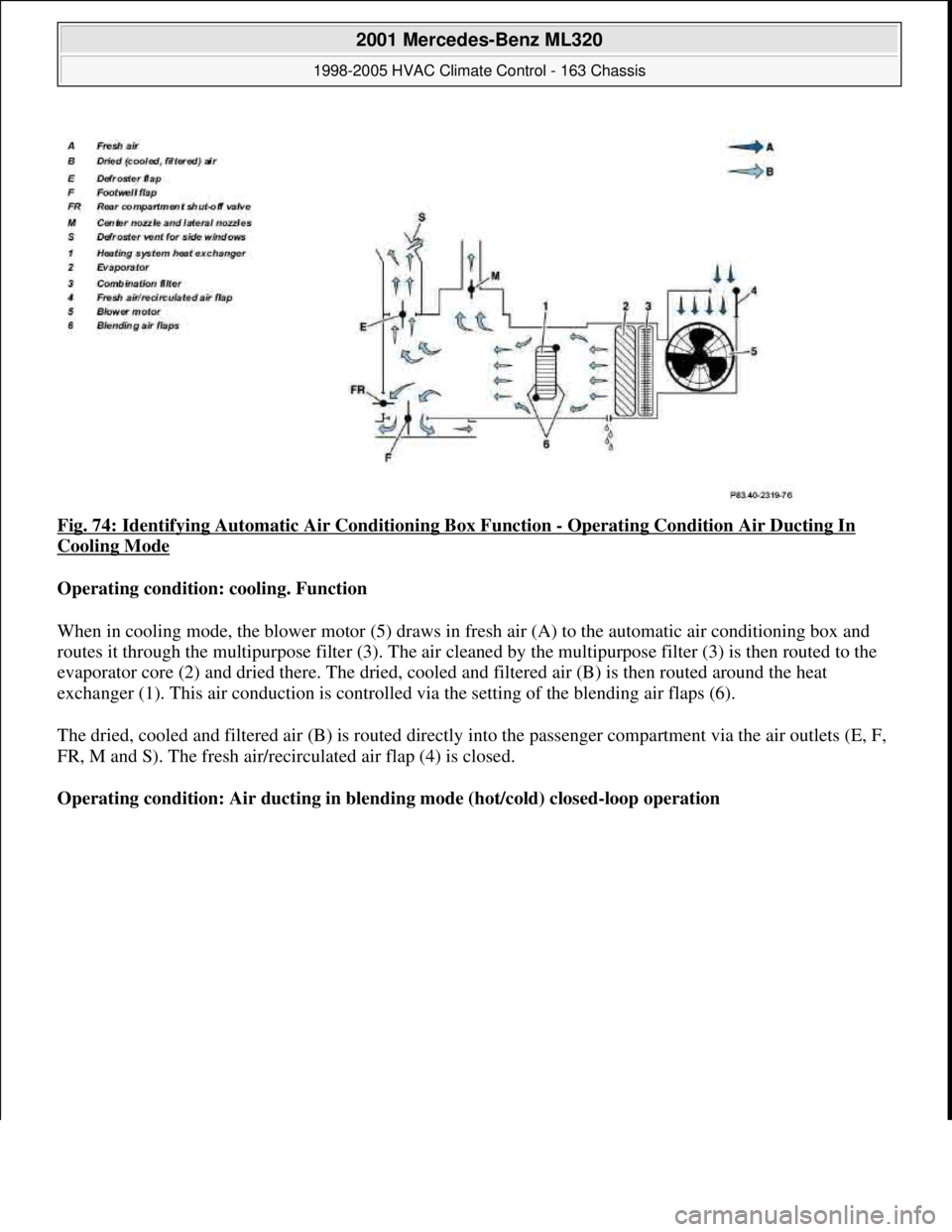
Fig. 74: Identifying Automatic Air Conditioning Box Function - Operating Condition Air Ducting In
Cooling Mode
Operating condition: cooling. Function
When in cooling mode, the blower motor (5) draws in fresh air (A) to the automatic air conditioning box and
routes it through the multipurpose filter (3). The air cleaned by the multipurpose filter (3) is then routed to the
evaporator core (2) and dried there. The dried, cooled and filtered air (B) is then routed around the heat
exchanger (1). This air conduction is controlled via the setting of the blending air flaps (6).
The dried, cooled and filtered air (B) is routed directly into the passenger compartment via the air outlets (E, F,
FR, M and S). The fresh air/recirculated air flap (4) is closed.
Operating condition: Air ducting in blending mode (hot/cold) closed-loop operation
2001 Mercedes-Benz ML320
1998-2005 HVAC Climate Control - 163 Chassis
me
Saturday, October 02, 2010 3:23:16 PMPage 92 © 2006 Mitchell Repair Information Company, LLC.
Page 3337 of 4133
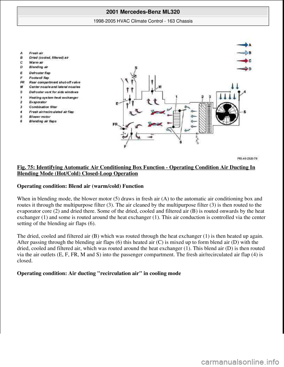
Fig. 75: Identifying Automatic Air Conditioning Box Function - Operating Condition Air Ducting In
Blending Mode (Hot/Cold) Closed-Loop Operation
Operating condition: Blend air (warm/cold) Function
When in blending mode, the blower motor (5) draws in fresh air (A) to the automatic air conditioning box and
routes it through the multipurpose filter (3). The air cleaned by the multipurpose filter (3) is then routed to the
evaporator core (2) and dried there. Some of the dried, cooled and filtered air (B) is routed onwards by the heat
exchanger (1) and some is routed around the heat exchanger (1). This air conduction is controlled via the center
setting of the blending air flaps (6).
The dried, cooled and filtered air (B) which was routed through the heat exchanger (1) is then heated up again.
After passing through the blending air flaps (6) this heated air (C) is mixed up to form blend air (D) with the
dried, cooled and filtered air, which was routed around the heat exchanger (1). This blend air (D) is then routed
via the air outlets (E, F, FR, M and S) into the passenger compartment. The fresh air/recirculated air flap (4) is
closed.
Operating condition: Air ducting "recirculation air" in cooling mode
2001 Mercedes-Benz ML320
1998-2005 HVAC Climate Control - 163 Chassis
me
Saturday, October 02, 2010 3:23:16 PMPage 93 © 2006 Mitchell Repair Information Company, LLC.
Page 3338 of 4133
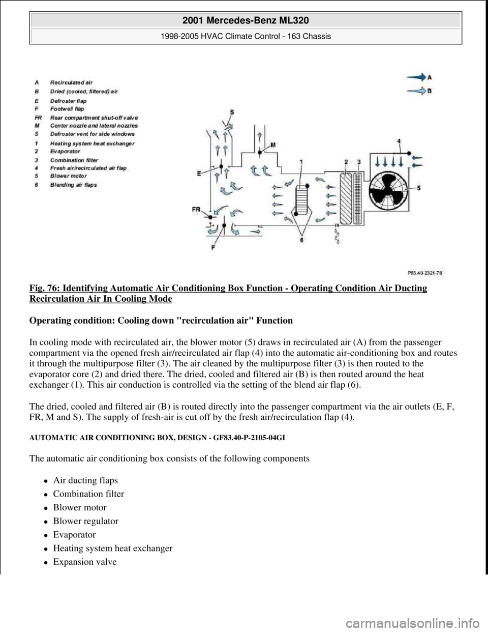
Fig. 76: Identifying Automatic Air Conditioning Box Function - Operating Condition Air Ducting
Recirculation Air In Cooling Mode
Operating condition: Cooling down "recirculation air" Function
In cooling mode with recirculated air, the blower motor (5) draws in recirculated air (A) from the passenger
compartment via the opened fresh air/recirculated air flap (4) into the automatic air-conditioning box and routes
it through the multipurpose filter (3). The air cleaned by the multipurpose filter (3) is then routed to the
evaporator core (2) and dried there. The dried, cooled and filtered air (B) is then routed around the heat
exchanger (1). This air conduction is controlled via the setting of the blend air flap (6).
The dried, cooled and filtered air (B) is routed directly into the passenger compartment via the air outlets (E, F,
FR, M and S). The supply of fresh-air is cut off by the fresh air/recirculation flap (4).
AUTOMATIC AIR CONDITIONING BOX, DESIGN - GF83.40-P-2105-04GI
The automatic air conditioning box consists of the following components
Air ducting flaps
Combination filter
Blower motor
Blower regulator
Evaporator
Heating system heat exchanger
Expansion valve
2001 Mercedes-Benz ML320
1998-2005 HVAC Climate Control - 163 Chassis
me
Saturday, October 02, 2010 3:23:16 PMPage 94 © 2006 Mitchell Repair Information Company, LLC.
Page 3340 of 4133
AC OFF BUTTON, FUNCTION - GF83.40-P-2107-01GI
Function
When the AC OFF button ( ) on the automatic air conditioning push-button control module is pressed an
LED comes on, the refrigerant compressor is switched off and cooling therefore switched off The air is no
longer cooled and dried.
Vehicles with diesel engine:
Additionally the electric heater booster is switched off. All other functions are retained.
In order to switch off the refrigerant compressor the push-button control module sends a switch-off request over
the CAN. At the same time, the compressor torque value is set to "0". After a specified time delay the
refrigerant compressor is switched off.
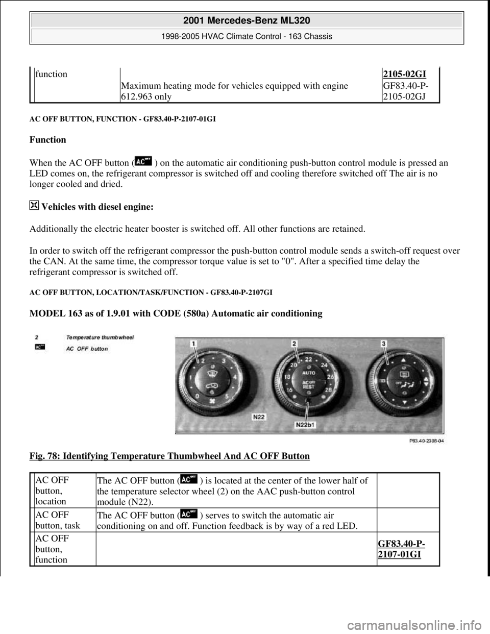
AC OFF BUTTON, LOCATION/TASK/FUNCTION - GF83.40-P-2107GI
MODEL 163 as of 1.9.01 with CODE (580a) Automatic air conditioning
Fig. 78: Identifying Temperature Thumbwheel And AC OFF Button
function2105-02GI
Maximum heating mode for vehicles equipped with engine
612.963 onlyGF83.40-P-
2105-02GJ
AC OFF
button,
locationThe AC OFF button ( ) is located at the center of the lower half of
the temperature selector wheel (2) on the AAC push-button control
module (N22).
AC OFF
button, taskThe AC OFF button ( ) serves to switch the automatic air
conditioning on and off. Function feedback is by way of a red LED.
AC OFF
button,
function
GF83.40-P-
2107-01GI
2001 Mercedes-Benz ML320
1998-2005 HVAC Climate Control - 163 Chassis
me
Saturday, October 02, 2010 3:23:16 PMPage 96 © 2006 Mitchell Repair Information Company, LLC.
Page 3344 of 4133
Fig. 80: Identifying AC Electric Suction Fan With Integrated Control
CONDENSER FUNCTION - GF83.40-P-2120-01GC
Function
The hot, gaseous refrigerant routed into the condenser passes the heat (compression heat) to the coiled pipes and
slats. These then very quickly absorb the refrigerant's heat and transmit the heat to the outside air passing
through. This in turn cools the refrigerant.
By cooling down, the refrigerant is liquefied (condensed). The liquid heat refrigerant is then carried away from
the condenser and flows into the fluid reservoir.
CONDENSER, LOCATION - GF83.40-P-2120-02GH
The condenser (7) is located directly in front of the radiator.
2001 Mercedes-Benz ML320
1998-2005 HVAC Climate Control - 163 Chassis
me
Saturday, October 02, 2010 3:23:16 PMPage 100 © 2006 Mitchell Repair Information Company, LLC.