1997 MERCEDES-BENZ ML430 cooling
[x] Cancel search: coolingPage 3313 of 4133
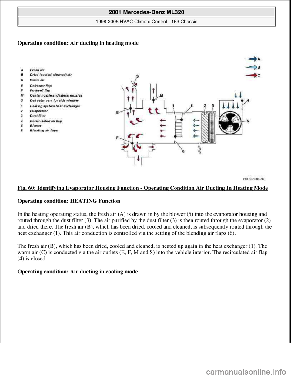
Operating condition: Air ducting in heating mode
Fig. 60: Identifying Evaporator Housing Function
- Operating Condition Air Ducting In Heating Mode
Operating condition: HEATING Function
In the heating operating status, the fresh air (A) is drawn in by the blower (5) into the evaporator housing and
routed through the dust filter (3). The air purified by the dust filter (3) is then routed through the evaporator (2)
and dried there. The fresh air (B), which has been dried, cooled and cleaned, is subsequently routed through the
heat exchanger (1). This air conduction is controlled via the setting of the blending air flaps (6).
The fresh air (B), which has been dried, cooled and cleaned, is heated up again in the heat exchanger (1). The
warm air (C) is conducted via the air outlets (E, F, M and S) into the vehicle interior. The recirculated air flap
(4) is closed.
Operating condition: Air ducting in cooling mode
2001 Mercedes-Benz ML320
1998-2005 HVAC Climate Control - 163 Chassis
me
Saturday, October 02, 2010 3:23:15 PMPage 69 © 2006 Mitchell Repair Information Company, LLC.
Page 3314 of 4133
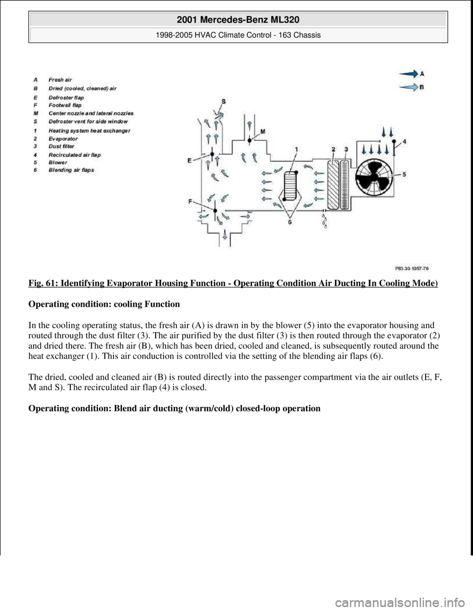
Fig. 61: Identifying Evaporator Housing Function - Operating Condition Air Ducting In Cooling Mode)
Operating condition: cooling Function
In the cooling operating status, the fresh air (A) is drawn in by the blower (5) into the evaporator housing and
routed through the dust filter (3). The air purified by the dust filter (3) is then routed through the evaporator (2)
and dried there. The fresh air (B), which has been dried, cooled and cleaned, is subsequently routed around the
heat exchanger (1). This air conduction is controlled via the setting of the blending air flaps (6).
The dried, cooled and cleaned air (B) is routed directly into the passenger compartment via the air outlets (E, F,
M and S). The recirculated air flap (4) is closed.
Operating condition: Blend air ducting (warm/cold) closed-loop operation
2001 Mercedes-Benz ML320
1998-2005 HVAC Climate Control - 163 Chassis
me
Saturday, October 02, 2010 3:23:15 PMPage 70 © 2006 Mitchell Repair Information Company, LLC.
Page 3315 of 4133
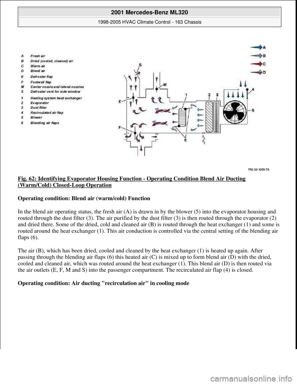
Fig. 62: Identifying Evaporator Housing Function - Operating Condition Blend Air Ducting
(Warm/Cold) Closed-Loop Operation
Operating condition: Blend air (warm/cold) Function
In the blend air operating status, the fresh air (A) is drawn in by the blower (5) into the evaporator housing and
routed through the dust filter (3). The air purified by the dust filter (3) is then routed through the evaporator (2)
and dried there. Some of the dried, cold and cleaned air (B) is routed through the heat exchanger (1) and some is
routed around the heat exchanger (1). This air conduction is controlled via the central setting of the blending air
flaps (6).
The air (B), which has been dried, cooled and cleaned by the heat exchanger (1) is heated up again. After
passing through the blending air flaps (6) this heated air (C) is mixed up to form blend air (D) with the dried,
cooled and cleaned air, which was routed around the heat exchanger (1). This blend air (D) is then routed via
the air outlets (E, F, M and S) into the passenger compartment. The recirculated air flap (4) is closed.
Operating condition: Air ducting "recirculation air" in cooling mode
2001 Mercedes-Benz ML320
1998-2005 HVAC Climate Control - 163 Chassis
me
Saturday, October 02, 2010 3:23:15 PMPage 71 © 2006 Mitchell Repair Information Company, LLC.
Page 3316 of 4133
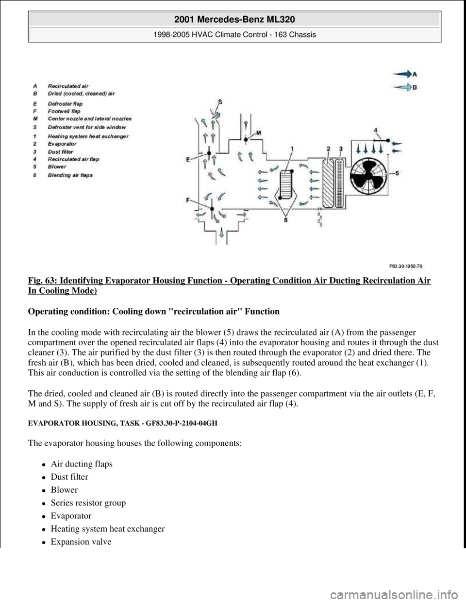
Fig. 63: Identifying Evaporator Housing Function - Operating Condition Air Ducting Recirculation Air
In Cooling Mode)
Operating condition: Cooling down "recirculation air" Function
In the cooling mode with recirculating air the blower (5) draws the recirculated air (A) from the passenger
compartment over the opened recirculated air flaps (4) into the evaporator housing and routes it through the dust
cleaner (3). The air purified by the dust filter (3) is then routed through the evaporator (2) and dried there. The
fresh air (B), which has been dried, cooled and cleaned, is subsequently routed around the heat exchanger (1).
This air conduction is controlled via the setting of the blending air flap (6).
The dried, cooled and cleaned air (B) is routed directly into the passenger compartment via the air outlets (E, F,
M and S). The supply of fresh air is cut off by the recirculated air flap (4).
EVAPORATOR HOUSING, TASK - GF83.30-P-2104-04GH
The evaporator housing houses the following components:
Air ducting flaps
Dust filter
Blower
Series resistor group
Evaporator
Heating system heat exchanger
Expansion valve
2001 Mercedes-Benz ML320
1998-2005 HVAC Climate Control - 163 Chassis
me
Saturday, October 02, 2010 3:23:15 PMPage 72 © 2006 Mitchell Repair Information Company, LLC.
Page 3317 of 4133
Blending air flap actuator
Recirculated air flap actuator motor
Electric heater booster (for engine 612.963 only) and therefore forms a complete unit.
The evaporator housing distributes the air that is required to ventilate the vehicle to the relevant air ducts and
vents depending on the required interior temperature.
The air ducting depends on various operating conditions such as:
Heating mode
Cooling mode
Blend air mode (cold/warm)
Cooling air mode with recirculated air
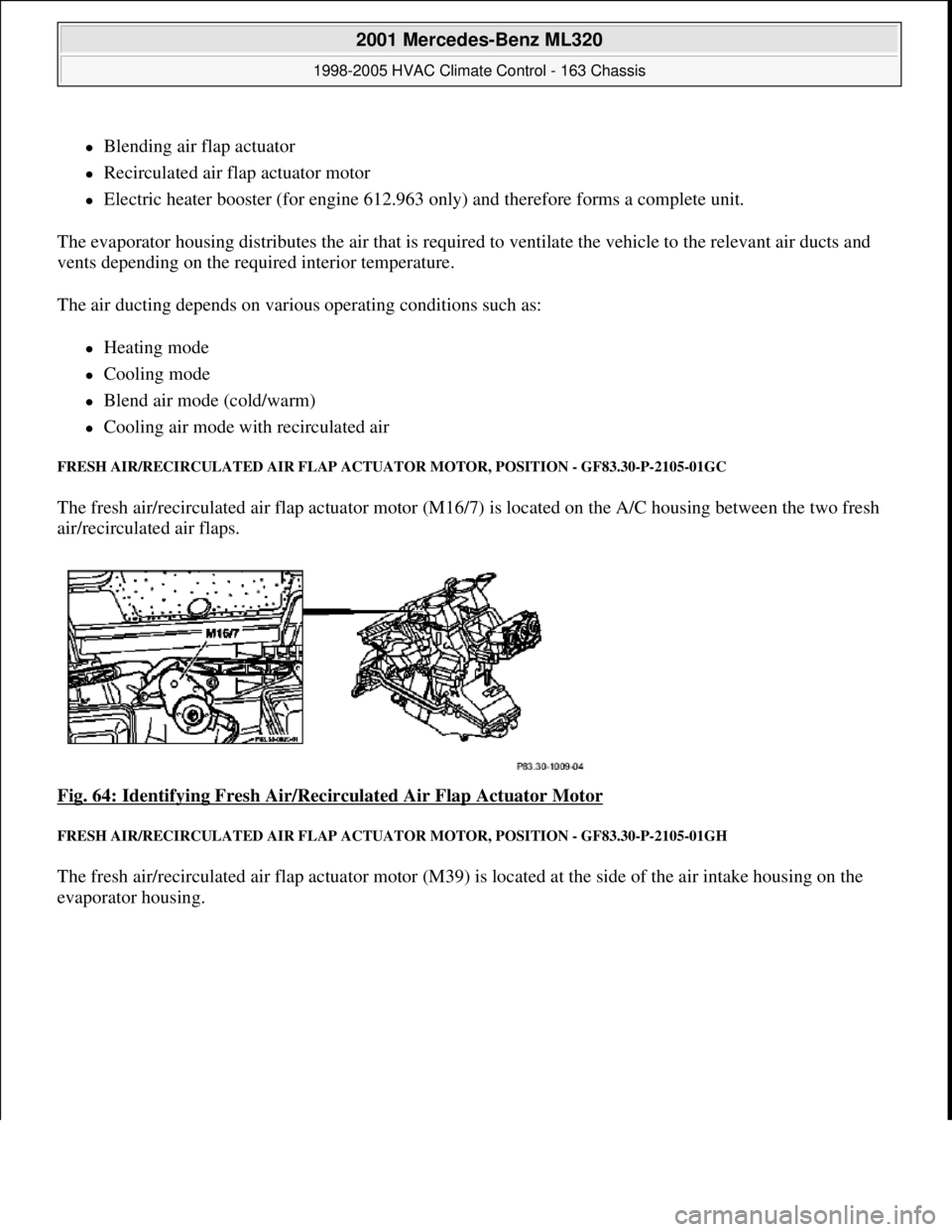
FRESH AIR/RECIRCULATED AIR FLAP ACTUATOR MOTOR, POSITION - GF83.30-P-2105-01GC
The fresh air/recirculated air flap actuator motor (M16/7) is located on the A/C housing between the two fresh
air/recirculated air flaps.
Fig. 64: Identifying Fresh Air/Recirculated Air Flap Actuator Motor
FRESH AIR/RECIRCULATED AIR FLAP ACTUATOR MOTOR, POSITION - GF83.30-P-2105-01GH
The fresh air/recirculated air flap actuator motor (M39) is located at the side of the air intake housing on the
evaporator housin
g.
2001 Mercedes-Benz ML320
1998-2005 HVAC Climate Control - 163 Chassis
me
Saturday, October 02, 2010 3:23:15 PMPage 73 © 2006 Mitchell Repair Information Company, LLC.
Page 3318 of 4133
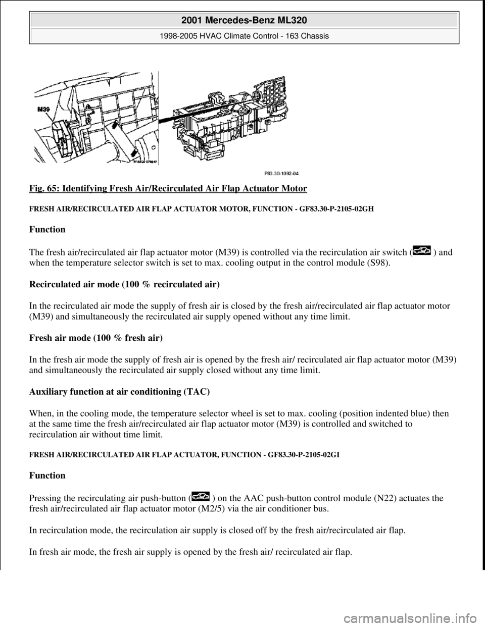
Fig. 65: Identifying Fresh Air/Recirc ulated Air Flap Actuator Motor
FRESH AIR/RECIRCULATED AIR FLAP ACTUATOR MOTO R, FUNCTION - GF83.30-P-2105-02GH
Function
The fresh air/recirculated air flap actuator motor (M39) is controlled via the recirculation air switch ( ) and
when the temperature selector switch is set to max. cooling output in the control module (S98).
Recirculated air mode (100 % recirculated air)
In the recirculated air mode the supply of fresh air is closed by the fresh air/recirculated air flap actuator motor
(M39) and simultaneously the recirculated air supply opened without any time limit.
Fresh air mode (100 % fresh air)
In the fresh air mode the supply of fresh air is opened by th e fresh air/ recirculated air flap actuator motor (M39)
and simultaneously the recirculated air supply closed without any time limit.
Auxiliary function at air conditioning (TAC)
When, in the cooling mode, the temperat ure selector wheel is set to max. cooling (position indented blue) then
at the same time the fres h air/recirculated air flap actuator moto r (M39) is controlled and switched to
recirculation air wi thout time limit.
FRESH AIR/RECIRCUL ATED AIR FLAP ACTUATOR, FU NCTION - GF83.30-P-2105-02GI
Function
Pressing the recirculating air push- button ( ) on the AAC push-button control module (N22) actuates the
fresh air/recirculated air flap actuator motor (M2/5) via the air conditioner bus.
In recirculation mode, the recircul ation air supply is closed off by th e fresh air/recirculated air flap.
In fresh air mode, the fresh air supply is ope ned by the fresh air/ recirculated air flap.
2001 Mercedes-Benz ML320
1998-2005 HVAC Climate Control - 163 Chassis
me
Saturday, October 02, 2010 3:23:15 PMPage 74 © 2006 Mitchell Repair Information Company, LLC.
Page 3324 of 4133
AUTOMATIC AIR CONDITIONING (AAC), FUNCTION - GF83.40-P-0001GI
MODEL 163 as of 1.9.01 with CODE (580a) Automatic air conditioning
Function
The automatic air conditioning (AAC) is equipped with an electronically regulated cooling, heating and
ventilating system and can be summed up by the following list of subfunctions.
Ventilation
The ventilation ensures that there is a sufficient supply of air within the passenger compartment.
Ventilation is achieved with the support of the blower during normal operation, when vehicle is standing
or to increase the air flow. The air is distributed in the passenger compartment using air distribution flaps.
Automatic air conditioning temperature control
The desired temperature is reached or held constant by cooling or heating the air. Precise temperature
control can be achieved by reading in the various temperature sensors.
Residual engine heat utilization
Electromagnetic clutch, location/purpose/
design/function GF83.55-P-
2101GH
In-car temperature sensor, location/purpose/ functionwith intake jet nozzle up to
30.11.99GF83.57-P-
2115GH
In-car temperature sensor with ventilation blower,
location/purpose/functionas of 1.12.99GF83.57-P-
2107GH
Ice-up protection temperature sensor, location/
purpose/function GF83.57-P-
2113GH
Blending air flap actuator, location/purpose/ function GF83.57-P-
2112GC
Outside temperature sensor, location/purpose/ functionas of 1.12.99GF83.57-P-
2110GH
Electric heater booster, location/purpose/
design/functionEngines 612.963 and 628.963GF83.70-P-
4054GH
Temperature regulator microswitch, location/
purpose/functionEngine 612.963GF83.70-P-
4055GH
Extended activity module, location/purpose GF54.21-P-
4106GH
Extended activity module, location/purpose/ designas of 1.12.99GF54.21-P-
4107GK
CDI control module, location/purpose/functionEngine 612.963GF07.16-P-
3102IA
2001 Mercedes-Benz ML320
1998-2005 HVAC Climate Control - 163 Chassis
me
Saturday, October 02, 2010 3:23:16 PMPage 80 © 2006 Mitchell Repair Information Company, LLC.
Page 3327 of 4133
AUTOMATIC AIR CONDITIONING PUSH-BUTTON CONTROL MODULE, FUNCTION - GF83.40-P-2000GI
MODEL 163 as of 1.9.01 with CODE (580a) Automatic air conditioning
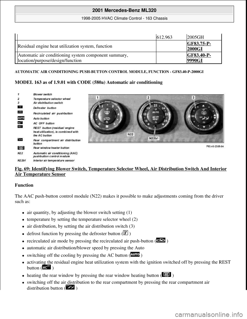
Fig. 69: Identifying Blower Switch , Temperature Selector Wheel, Air Di stribution Switch And Interior
Air Temperature Sensor
Function
The AAC push-button control module (N 22) makes it possible to make adjustments coming from the driver
such as:
air quantity, by adjusting the blower switch setting (1)
temperature by setting the temp erature selector wheel (2)
air distribution, by setting the air distribution switch (3)
defrost function by pressing the defroster button ( )
recirculated air mode by pressing th e recirculated air push-button ( )
automatic air distribution/blower speed by pressing the Auto
switching off the cooling by pressing the AC button ( )
activating the residual engine heat ut ilization system with the ignition switched of f by pressing the REST
button ( )
heating the rear window by pressing the rear window heating button ( )
switching off the air distribution to the rear compartment by pressing the rear compartment air
distribution button ( )
612.9632005GH
Residual engine heat util ization system, function GF83.75-P-
2000GI
Automatic air conditioning sy stem component summary,
location/purpose/design/function GF83.40-P-
9990GI
2001 Mercedes-Benz ML320
1998-2005 HVAC Climate Control - 163 Chassis
me
Saturday, October 02, 2010 3:23:16 PMPage 83 © 2006 Mitchell Repair Information Company, LLC.