1997 MERCEDES-BENZ ML430 cooling
[x] Cancel search: coolingPage 2094 of 4133
P01.30-0299-06
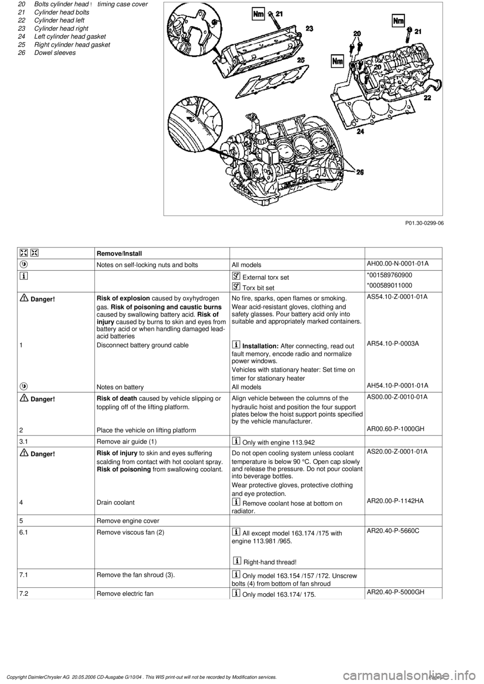
20
Bolts cylinder head
!
timing case cover
21
Cylinder head bolts
22
Cylinder head left
23
Cylinder head right
24
Left cylinder head gasket
25
Right cylinder head gasket
26
Dowel sleeves
Remove/Install
Notes on self-locking nuts and bolts
All models
AH00.00-N-0001-01A
External torx set
*001589760900
Torx bit set
*000589011000
Danger!
Risk of explosion
caused by oxyhydrogen
gas.
Risk of poisoning and caustic burns
caused by swallowing battery acid.
Risk of
injury caused by burns to skin and eyes from
battery acid or when handling damaged lead-
acid batteries
No fire, sparks, open flames or smoking.
Wear acid-resistant gloves, clothing and
safety glasses. Pour battery acid only into
suitable and appropriately marked containers.
AS54.10-Z-0001-01A
1
Disconnect battery ground cable
Installation:
After connecting, read out
fault memory, encode radio and normalize
power windows.
Vehicles with stationary heater: Set time on
timer for stationary heater
AR54.10-P-0003A
Notes on battery
All models
AH54.10-P-0001-01A
Danger!
Risk of death
caused by vehicle slipping or
toppling off of the lifting platform.
Align vehicle between the columns of the
hydraulic hoist and position the four support
plates below the hoist support points specified
by the vehicle manufacturer.
AS00.00-Z-0010-01A
2
Place the vehicle on lifting platform
AR00.60-P-1000GH
3.1
Remove air guide (1)
Only with engine 113.942
Danger!
Risk of injury
to skin and eyes suffering
scalding from contact with hot coolant spray.
Risk of poisoning
from swallowing coolant.
Do not open cooling system unless coolant
temperature is below 90 °C. Open cap slowly
and release the pressure. Do not pour coolant
into beverage bottles.
Wear protective gloves, protective clothing
and eye protection.
AS20.00-Z-0001-01A
4
Drain coolant
Remove coolant hose at bottom on
radiator.
AR20.00-P-1142HA
5
Remove engine cover
6.1
Remove viscous fan (2)
All except model 163.174 /175 with
engine 113.981 /965.
Right-hand thread!
AR20.40-P-5660C
7.1
Remove the fan shroud (3).
Only model 163.154 /157 /172. Unscrew
bolts (4) from bottom of fan shroud
7.2
Remove electric fan
Only model 163.174/ 175.
AR20.40-P-5000GH
Copyright DaimlerChrysler AG 20.05.2006 CD-Ausgabe G/10/04 . This WIS print-out will not be recorde
d by Modification services.
Page 2
Page 2097 of 4133

29
Slacken cylinder head bolts (21) in stages,
unscrew
Loosen cylinder head bolts according to
loosening schematic only after engine has
cooled down to prevent cylinder head from
distorting.
AR01.30-P-5800-09B
Installation:
Observe tightening pattern
and tightening instructions of cylinder head
bolts.
Oil thread and head contact surface of
cylinder head bolts.
AR01.30-P-5800-07B
Screwdriver insert
*000589031000
Screwdriver insert
*000589041000
*BA01.30-P-1001-01D
30
Remove cylinder head
Installation:
On Engine 112/113 observe
porous points in the left and right cylinder
head. If porous points are present, sealant
must be applied to the cylinder head gasket.
Notes on application of sealant to cylinder
head gasket.
Engine 112, 113
AH01.30-P-1000-04VA
The sealant must be applied within
10 minutes.
Loctite 5900 sealant.
*BR00.45-Z-1015-01A
31
Inspect version of cylinder head gasket
Assignment of cylinder head gasket
Information for assigning the cylinder head
gaskets
Engine 112, 113
AH01.30-P-1000-06V
32
Check cylinder head bolts (21)
AR01.30-P-5800-03B
*BE01.30-P-1001-04B
33
Clean sealing surfaces, inspect for cracks,
shrink holes and flatness, clean threaded
holes.
Pay attention to dowel sleeves (26) for
locating the cylinder head.
Sealing surfaces of crankcase and
cylinder head are provided with an 0.8 mm
thick silicone layer during series production.
At the time of repair installation, silicone
sealant is applied to the sealing area only in
case of any shrink holes.
The sealant must be applied within
10 minutes.
Loctite 5900 sealant.
*BR00.45-Z-1015-01A
34
Install in the reverse order
Danger!
Risk of accident
caused by vehicle starting
off by itself when engine is running.
Risk of
injury
caused by contusions and burns when
working in engine during starting procedure
Secure vehicle to prevent it from moving.
Wear closed and snug-fitting work clothes.
Do not grasp hot or rotating parts.
AS00.00-Z-0005-01A
35
Run engine and inspect for leaks
36
Inspect cooling system for leaks
Warm up engine to operating temperature
and then inspect cooling system or leaks.
AR20.00-P-1010HA
37
Read out and erase fault memory
Stored faults which can result from cables
being disconnected or from simulation during
removal and installation or test work, have to
be processed and erased in the fault
memories after completing the work:
#
Diagnosis Manual Volume 2 Index 0:
Connecting and using test equipment.
Cylinder head/cylinder head bolts
Number
Designation
Engine
112.910/911/912/
913/914/915/
916/917/920/
921/922/923/
940/941/942/
943/944/945/
946/947/949/
951/953/954/
955/960/961/
970/972/973/975
Engine
113.940/941/
942/943/944/
945/946/948/
960/961/962/
963/965/966/
967/968/969/
980/981/982/
984/986/987/
988/990/991/
992/993
BE01.30-P-1001-04B
Cylinder head bolt
Thread diameter
M
1111
Length (L) when new
mm
141.5141.5
Length (L)
mm
T
144.5
T
144.5
Copyright DaimlerChrysler AG 20.05.2006 CD-Ausgabe G/10/04 . This WIS print-out will not be recorde
d by Modification services.
Page 5
Page 2141 of 4133
2001 MERCEDES-BENZ
ML320 & ML430
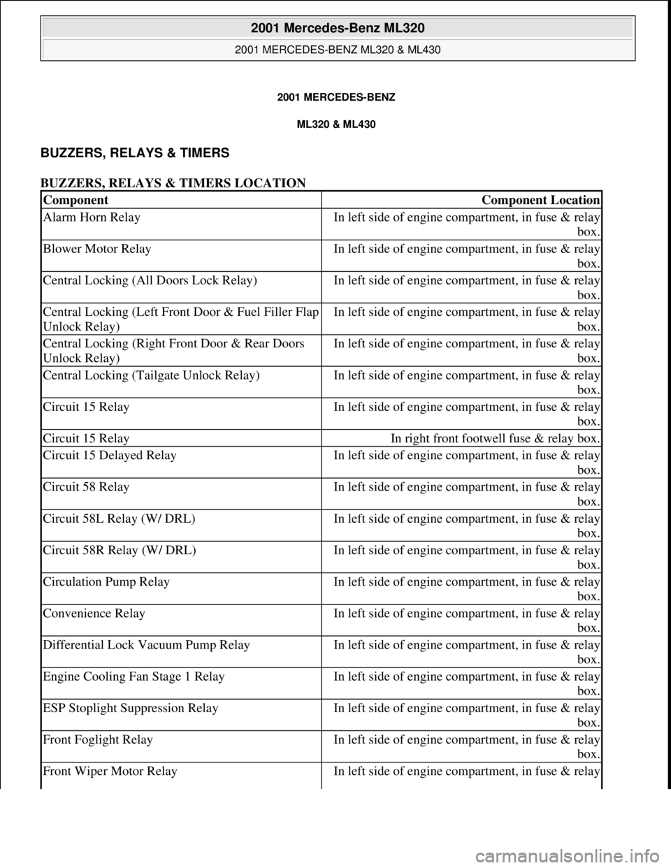
BUZZERS, RELAYS & TIMERS
BUZZERS, RELAYS & TIMERS LOCATION
ComponentComponent Location
Alarm Horn RelayIn left side of engine compartment, in fuse & relay
box.
Blower Motor RelayIn left side of engine compartment, in fuse & relay
box.
Central Locking (All Doors Lock Relay)In left side of engine compartment, in fuse & relay
box.
Central Locking (Left Front Door & Fuel Filler Flap
Unlock Relay)In left side of engine compartment, in fuse & relay
box.
Central Locking (Right Front Door & Rear Doors
Unlock Relay)In left side of engine compartment, in fuse & relay
box.
Central Locking (Tailgate Unlock Relay)In left side of engine compartment, in fuse & relay
box.
Circuit 15 RelayIn left side of engine compartment, in fuse & relay
box.
Circuit 15 RelayIn right front footwell fuse & relay box.
Circuit 15 Delayed RelayIn left side of engine compartment, in fuse & relay
box.
Circuit 58 RelayIn left side of engine compartment, in fuse & relay
box.
Circuit 58L Relay (W/ DRL)In left side of engine compartment, in fuse & relay
box.
Circuit 58R Relay (W/ DRL)In left side of engine compartment, in fuse & relay
box.
Circulation Pump RelayIn left side of engine compartment, in fuse & relay
box.
Convenience RelayIn left side of engine compartment, in fuse & relay
box.
Differential Lock Vacuum Pump RelayIn left side of engine compartment, in fuse & relay
box.
Engine Cooling Fan Stage 1 RelayIn left side of engine compartment, in fuse & relay
box.
ESP Stoplight Suppression RelayIn left side of engine compartment, in fuse & relay
box.
Front Foglight RelayIn left side of engine compartment, in fuse & relay
box.
Front Wiper Motor RelayIn left side of engine compartment, in fuse & relay
2001 Mercedes-Benz ML320
2001 MERCEDES-BENZ ML320 & ML430
2001 Mercedes-Benz ML320
2001 MERCEDES-BENZ ML320 & ML430
me
Saturday, October 02, 2010 3:21:17 PMPage 1 © 2006 Mitchell Repair Information Company, LLC.
me
Saturday, October 02, 2010 3:21:20 PMPage 1 © 2006 Mitchell Repair Information Company, LLC.
Page 2143 of 4133
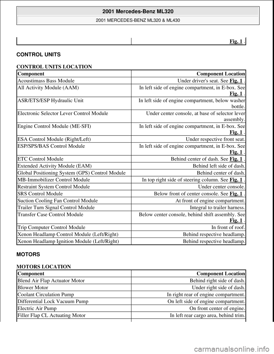
CONTROL UNITS
CONTROL UNITS LOCATION
MOTORS
MOTORS LOCATION
Fig. 1 .
ComponentComponent Location
Acoustimass Bass ModuleUnder driver's seat. See Fig. 1 .
All Activity Module (AAM)In left side of engine compartment, in E-box. See
Fig. 1
.
ASR/ETS/ESP Hydraulic UnitIn left side of engine compartment, below washer
bottle.
Electronic Selector Lever Control ModuleUnder center console, at base of selector lever
assembly.
Engine Control Module (ME-SFI)In left side of engine compartment, in E-box. See
Fig. 1
.
ESA Control Module (Right/Left)Under respective front seat.
ESP/SPS/BAS Control ModuleIn left side of engine compartment, in E-box. See
Fig. 1
.
ETC Control ModuleBehind center of dash. See Fig. 1 .
Extended Activity Module (EAM)Behind left side of dash.
Global Positioning System (GPS) Control ModuleBehind center of dash.
MB-Immobilizer Control ModuleIn top right side of steering column. See Fig. 1 .
Restraint System Control ModuleUnder center console.
SRS Control ModuleBelow front of center console. See Fig. 1 .
Suction Cooling Fan Control ModuleAt front of engine compartment.
Trailer Turn Signal Control ModuleIntegral to trailer harness.
Transfer Case Control ModuleBelow center console, behind shift assembly. See
Fig. 1
.
Trip Computer Control ModuleIn front of roof.
Xenon Headlamp Control Module (Left/Right)Behind respective headlamp.
Xenon Headlamp Ignition Module (Left/Right)Behind respective headlamp.
ComponentComponent Location
Blend Air Flap Actuator MotorBehind right side of dash.
Blower MotorUnder right side of dash.
Coolant Circulation PumpIn right rear of engine compartment.
Differential Lock Vacuum PumpOn left side of engine compartment.
Electric Air PumpOn front center of engine.
Filler Flap CL Actuating MotorIn left rear cargo area, behind trim.
2001 Mercedes-Benz ML320
2001 MERCEDES-BENZ ML320 & ML430
me
Saturday, October 02, 2010 3:21:17 PMPage 3 © 2006 Mitchell Repair Information Company, LLC.
Page 2379 of 4133
The sealing compound must only be applied to the speci fied surfaces in the form of a bead of 2.0 mm ± 0.5
mm in diameter.
The sealing compound must be processe d within 10 min. The sealing compound bead must not be spread. Only
the sealing compound listed in the s ection Repair products may be used.
TROUBLE DIAGNOSIS
GURGLING NOISE IN HEA TER HOUSING - AF01.30-P-1000AG
ENGINE 113.##### up to 286599 in MODEL 129, 163, 202, 208, 210, 215, 220
ENGINE 113.### ## up to 286599 in MODEL 463
Modification notes
17.1.01Replaces STIP 20.10-004 dated 17.01.2001
Damage
codeCauseRemedy
01 243 B2
Heater return duct in cylinder
head clogged with casting
crust
Before working on the cooling system,
coolant pump, heater housing, etc.:?
1 Remove left cylinder head
ENGINE 113 in MODEL 210, 208, 202, 129AR01.30-P-
5800B
ENGINE 113 in MODEL 220AR01.30-P-
5800BA
ENGINE 112.945, 113.962 in MODEL 463AR01.30-P-
5800GV
ENGINE 113.942 in MODEL 163.172
ENGINE 113.981 in MODEL 163.174AR01.30-P-
5800MV
2 Check coolant duct, if necessary, remove
possible casting crust
As of engine end number 285600 (as of
beginning of 01/2001) there is no casting crust
at this point.
2001 Mercedes-Benz ML320
1998-2005 ENGINE Complete engine - 163 Chassis
me
Saturday, October 02, 2010 3:17:56 PMPage 23 © 2006 Mitchell Repair Information Company, LLC.
Page 2380 of 4133

Fig. 15: Locating Casting Crust In Cooling Duct
COOLANT TEMPERATURE HIGHER THAN NORMAL - AF01.30-P-8000A
ENGINE 113.##### up to 286599 in MODEL 129, 163, 202, 208, 210, 215, 220
ENGINE 113.### ## up to 286599 in MODEL 463
Modification notes
17.1.01Supersedes STIP 20.10-004 dated 17.01.2001
Damage
codeCauseRemedy
01 243 B2
Cylinder head with
casting crust in
coolant duct
Before performing work on cooling system, coolant
pump, heater housing, etc.: ?
1. Remove left cylinder head
ENGINE 113 in MODEL 210, 208, 202, 129AR01.30-P-
5800B
ENGINE 113 in MODEL 220AR01.30-P-
5800BA
ENGINE 112.945, 113.962 in MODEL 463AR01.30-P-
5800GV
ENGINE 113.942 in MODEL 163.172AR01.30-P-
5800MV
ENGINE 113.981 in MODEL 163.174
2 Check coolant duct, if necessary, remove possible casting
crust As of engine end number (as of beginning of
01/2001) there is no casting crust at this point.
2001 Mercedes-Benz ML320
1998-2005 ENGINE Complete engine - 163 Chassis
me
Saturday, October 02, 2010 3:17:56 PMPage 24 © 2006 Mitchell Repair Information Company, LLC.
Page 2381 of 4133
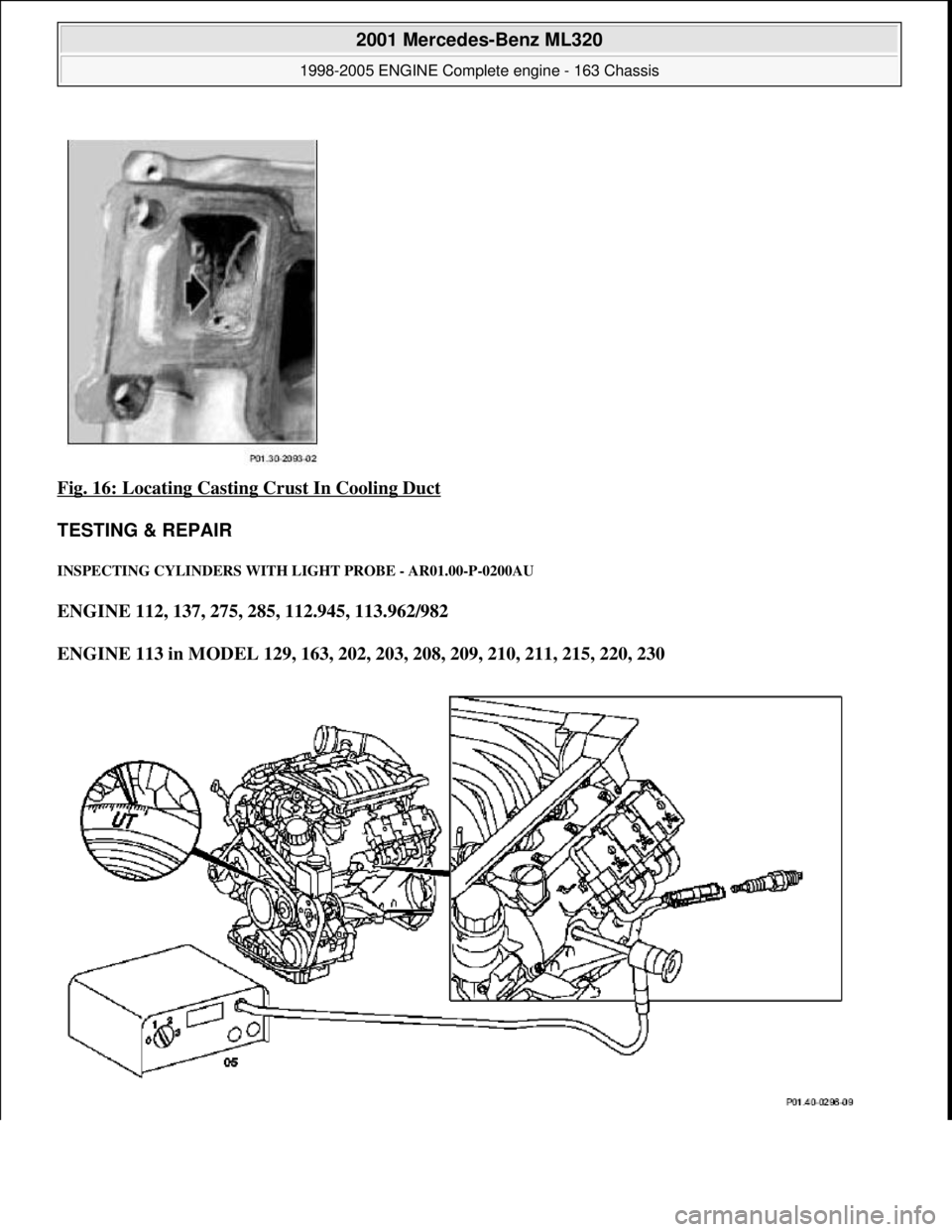
Fig. 16: Locating Casting Crust In Cooling Duct
TESTING & REPAIR
INSPECTING CY LINDERS WITH LIGHT PROBE - AR01.00-P-0200AU
ENGINE 112, 137, 275, 285, 112.945, 113.962/982
ENGINE 113 in MODEL 129, 163, 202, 203, 208, 209, 210, 211, 215, 220, 230
2001 Mercedes-Benz ML320
1998-2005 ENGINE Complete engine - 163 Chassis
me
Saturday, October 02, 2010 3:17:56 PMPage 25 © 2006 Mitchell Repair Information Company, LLC.
Page 2396 of 4133
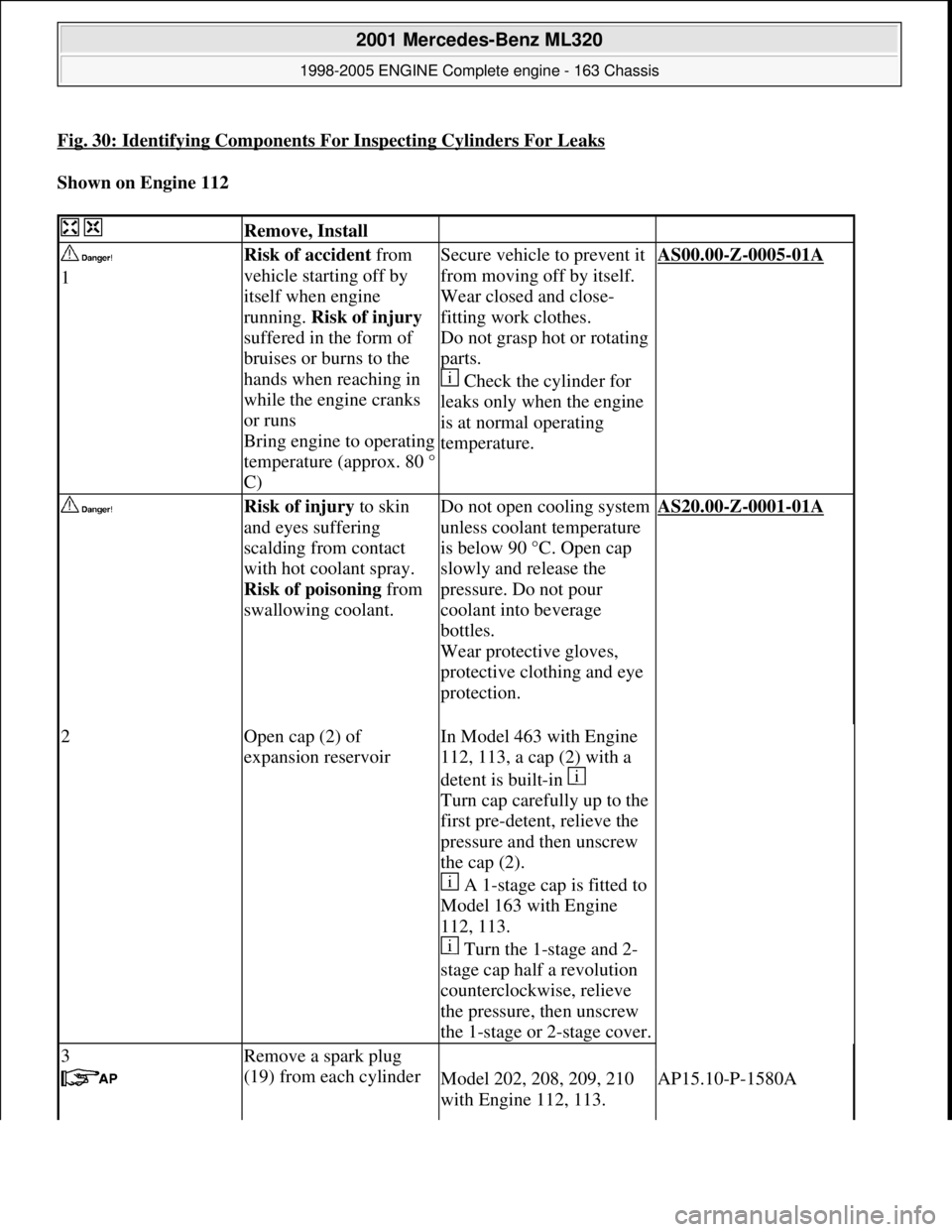
Fig. 30: Identifying Components For Inspecting Cylinders For Leaks
Shown on Engine 112
Remove, Install
1Risk of accident from
vehicle starting off by
itself when engine
running. Risk of injury
suffered in the form of
bruises or burns to the
hands when reaching in
while the engine cranks
or runs
Bring engine to operating
temperature (approx. 80 °
C)Secure vehicle to prevent it
from moving off by itself.
Wear closed and close-
fitting work clothes.
Do not grasp hot or rotating
parts.
Check the cylinder for
leaks only when the engine
is at normal operating
temperature.AS00.00-Z-0005-01A
Risk of injury to skin
and eyes suffering
scalding from contact
with hot coolant spray.
Risk of poisoning from
swallowing coolant.
Do not open cooling system
unless coolant temperature
is below 90 °C. Open cap
slowly and release the
pressure. Do not pour
coolant into beverage
bottles.
Wear protective gloves,
protective clothing and eye
protection.
AS20.00-Z-0001-01A
2Open cap (2) of
expansion reservoirIn Model 463 with Engine
112, 113, a cap (2) with a
detent is built-in
Turn cap carefully up to the
first pre-detent, relieve the
pressure and then unscrew
the cap (2).
A 1-stage cap is fitted to
Model 163 with Engine
112, 113.
Turn the 1-stage and 2-
stage cap half a revolution
counterclockwise, relieve
the pressure, then unscrew
the 1-stage or 2-stage cover.
3Remove a spark plug
(19) from each cylinder
Model 202, 208, 209, 210
with Engine 112, 113.AP15.10-P-1580A
2001 Mercedes-Benz ML320
1998-2005 ENGINE Complete engine - 163 Chassis
me
Saturday, October 02, 2010 3:17:56 PMPage 40 © 2006 Mitchell Repair Information Company, LLC.