1997 MERCEDES-BENZ ML430 cooling
[x] Cancel search: coolingPage 1407 of 4133
Holding Pressure Shift Valve, Location/Task/Design/Function
See HOLDING PRESSURE SHIFT VALVE, LOCATION/TASK/FUNCTION
.
Shift Pressure Shift Valve, Location/Task/Function
See SHIFT PRESSURE SHIFT VALVE, LOCATION/TASK/FUNCTION
.
Overlap Regulating Valve, Location/Task/Function
See OVERLAP REGULATING VALVE, LOCATION/TASK/FUNCTION
.
Location/Task/Function Of Command Valve
See LOCATION/TASK/FUNCTION OF COMMAND VALVE
.
Selector Valve, Location/Task
See SELECTOR VALVE, LOCATION/TASK
.
Location/Task/Design/Function Of Oil Pump
See LOCATION/TASK/DESIGN/FUNCTION OF OIL PUMP
.
Lubricating Pressure, Function
Operation
The working pressure regulating valve diverts surplus oil to the lubrication pressure regulating valve, from
where it is controlled and used for lubricating and cooling the mechanical transmission and torque converter. In
addition the pressure in the torque converter is limited via the lubrication pressure.
Working Pressure Regulating Valve, Location/Task/Function
See WORKING PRESSURE REGULATING VALVE, LOCATION/TASK/FUNCTION
.
Lubrication Pressure Regulating Valve, Location/Task/Function
See LUBRICATION PRESSURE REGULATING VALVE, LOCATION/TASK/FUNCTION
.
Torque Converter Lockup Clutch Regulating Valve, Location/Task/Function
See SHIFT PRESSURE REGULATING VALVE, LOCATION/TASK/FUNCTION
.
Upshift/Downshift Solenoid Valve, Location/Task/Design/Function
See UPSHIFT/DOWNSHIFT SOLENOID VALVE, LOCATION/TASK/DESIGN/FUNCTION
.
2001 Mercedes-Benz ML320
1998-03 AUTOMATIC TRANSMISSIONS Complete Transmissions - ML 320 - 722.662
me
Saturday, October 02, 2010 3:15:29 PMPage 238 © 2006 Mitchell Repair Information Company, LLC.
Page 1780 of 4133
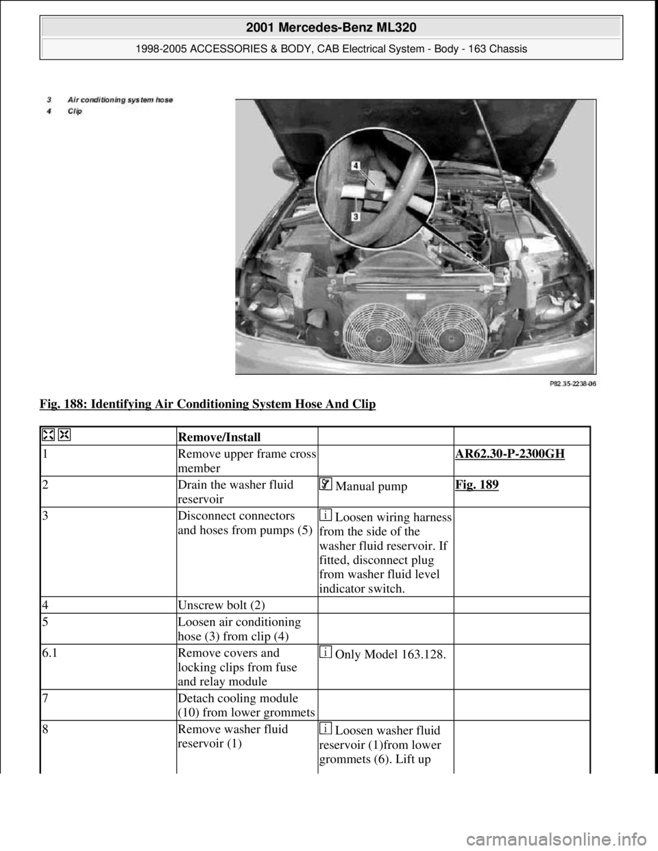
Fig. 188: Identifying Air Conditioning System Hose And Clip
Remove/Install
1Remove upper frame cross
member AR62.30-P-2300GH
2Drain the washer fluid
reservoir Manual pumpFig. 189
3Disconnect connectors
and hoses from pumps (5)Loosen wiring harness
from the side of the
washer fluid reservoir. If
fitted, disconnect plug
from washer fluid level
indicator switch.
4Unscrew bolt (2)
5Loosen air conditioning
hose (3) from clip (4)
6.1Remove covers and
locking clips from fuse
and relay module Only Model 163.128.
7Detach cooling module
(10) from lower grommets
8Remove washer fluid
reservoir (1) Loosen washer fluid
reservoir (1)from lower
grommets (6). Lift up
2001 Mercedes-Benz ML320
1998-2005 ACCESSORIES & BODY, CAB Electrical System - Body - 163 Chassis
me
Saturday, October 02, 2010 3:30:09 PMPage 285 © 2006 Mitchell Repair Information Company, LLC.
Page 1781 of 4133
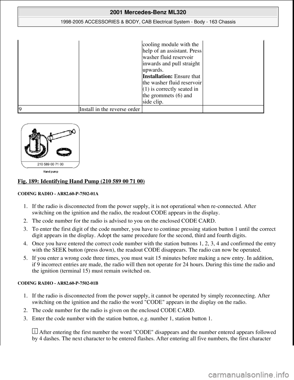
Fig. 189: Identifying Hand Pump (210 589 00 71 00)
CODING RADIO - AR82.60-P-7502-01A
1. If the radio is disconnected from the power supply, it is not operational when re-connected. After
switching on the ignition and the radio, the readout CODE appears in the display.
2. The code number for the radio is advised to you on the enclosed CODE CARD.
3. To enter the first digit of the code number, you have to continue pressing station button 1 until the correct
digit appears in the display. Adopt the same procedure for the second, third and fourth digits.
4. Once you have entered the correct code number with the station buttons 1, 2, 3, 4 and confirmed the entry
with the SEEK button (press down), the readout CODE disappears. The radio can now be operated.
5. If you enter a wrong code three times, you must wait 15 minutes before making a new entry. In addition,
if 9 incorrect entries are made, the radio will then not operate for 24 hours. During this time the radio and
the ignition (terminal 15) must remain switched on.
CODING RADIO - AR82.60-P-7502-01B
1. If the radio is disconnected from the power supply, it cannot be operated by simply reconnecting. After
switching on the ignition and the radio the word "CODE" appears in the display on the radio.
2. The code number for the radio is given on the enclosed CODE CARD.
3. Enter the code number with the station button, e.g. number 1, station button 1.
After entering the first number the word "CODE" disappears and the number entered appears followed
by 4 dashes. The next character to be entered flashes. After entering all five numbers, the first character
cooling module with the
help of an assistant. Press
washer fluid reservoir
inwards and pull straight
upwards.
Installation: Ensure that
the washer fluid reservoir
(1) is correctly seated in
the grommets (6) and
side clip.
9Install in the reverse order
2001 Mercedes-Benz ML320
1998-2005 ACCESSORIES & BODY, CAB Electrical System - Body - 163 Chassis
me
Saturday, October 02, 2010 3:30:09 PMPage 286 © 2006 Mitchell Repair Information Company, LLC.
Page 1961 of 4133
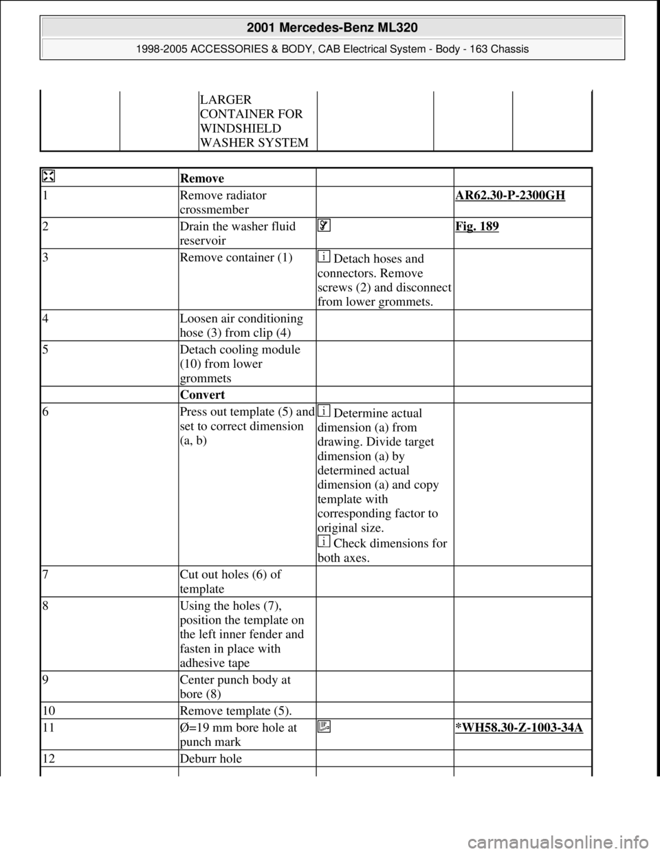
LARGER
CONTAINER FOR
WINDSHIELD
WASHER SYSTEM
Remove
1Remove radiator
crossmember AR62.30-P-2300GH
2Drain the washer fluid
reservoir Fig. 189
3Remove container (1) Detach hoses and
connectors. Remove
screws (2) and disconnect
from lower grommets.
4Loosen air conditioning
hose (3) from clip (4)
5Detach cooling module
(10) from lower
grommets
Convert
6Press out template (5) and
set to correct dimension
(a, b) Determine actual
dimension (a) from
drawing. Divide target
dimension (a) by
determined actual
dimension (a) and copy
template with
corresponding factor to
original size.
Check dimensions for
both axes.
7Cut out holes (6) of
template
8Using the holes (7),
position the template on
the left inner fender and
fasten in place with
adhesive tape
9Center punch body at
bore (8)
10Remove template (5).
11Ø=19 mm bore hole at
punch mark *WH58.30-Z-1003-34A
12Deburr hole
2001 Mercedes-Benz ML320
1998-2005 ACCESSORIES & BODY, CAB Electrical System - Body - 163 Chassis
me
Saturday, October 02, 2010 3:30:14 PMPage 466 © 2006 Mitchell Repair Information Company, LLC.
Page 1962 of 4133
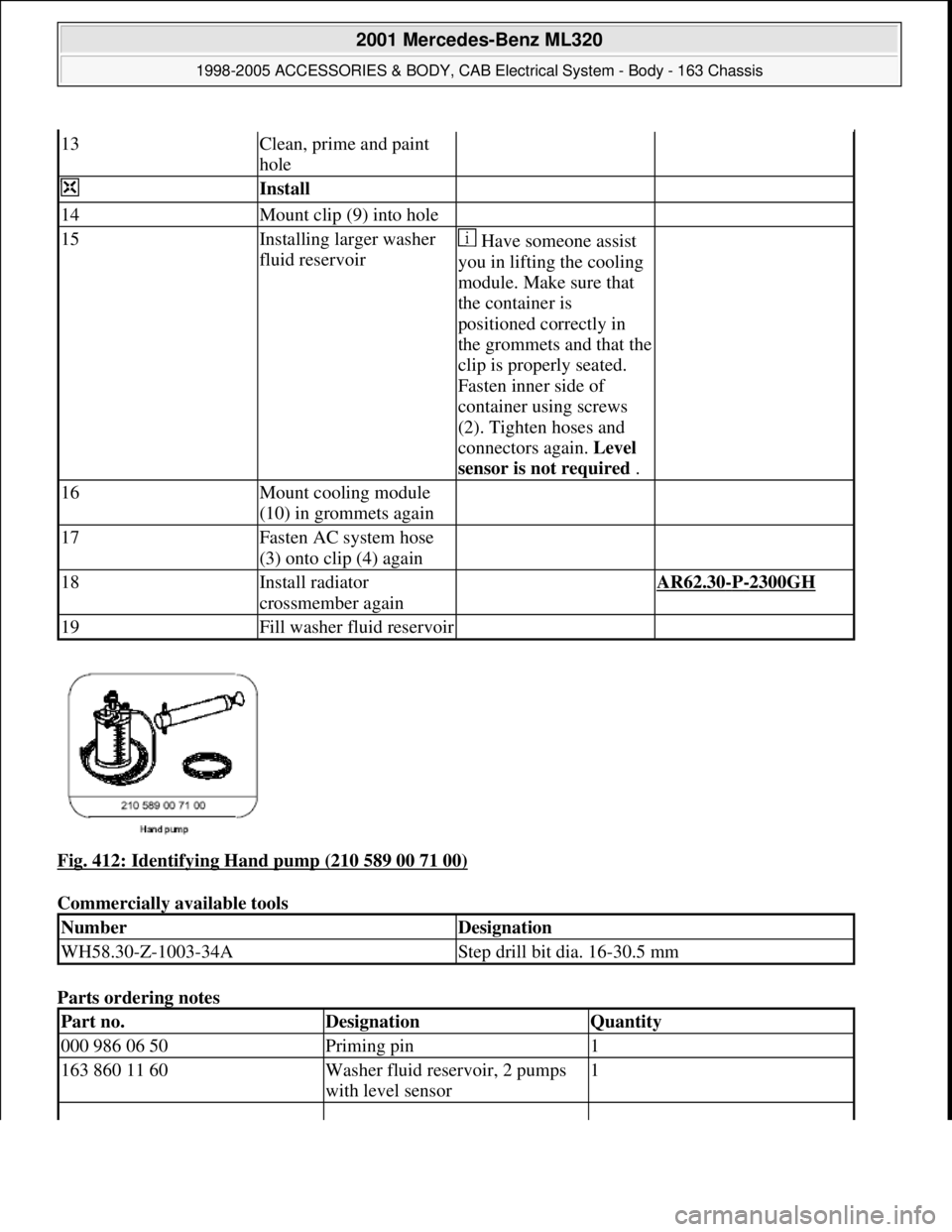
Fig. 412: Identifying Hand pump (210 589 00 71 00)
Commercially available tools
Parts ordering notes
13Clean, prime and paint
hole
Install
14Mount clip (9) into hole
15Installing larger washer
fluid reservoir Have someone assist
you in lifting the cooling
module. Make sure that
the container is
positioned correctly in
the grommets and that the
clip is properly seated.
Fasten inner side of
container using screws
(2). Tighten hoses and
connectors again. Level
sensor is not required .
16Mount cooling module
(10) in grommets again
17Fasten AC system hose
(3) onto clip (4) again
18Install radiator
crossmember again AR62.30-P-2300GH
19Fill washer fluid reservoir
NumberDesignation
WH58.30-Z-1003-34AStep drill bit dia. 16-30.5 mm
Part no.DesignationQuantity
000 986 06 50Priming pin1
163 860 11 60Washer fluid reservoir, 2 pumps
with level sensor1
2001 Mercedes-Benz ML320
1998-2005 ACCESSORIES & BODY, CAB Electrical System - Body - 163 Chassis
me
Saturday, October 02, 2010 3:30:14 PMPage 467 © 2006 Mitchell Repair Information Company, LLC.
Page 2068 of 4133
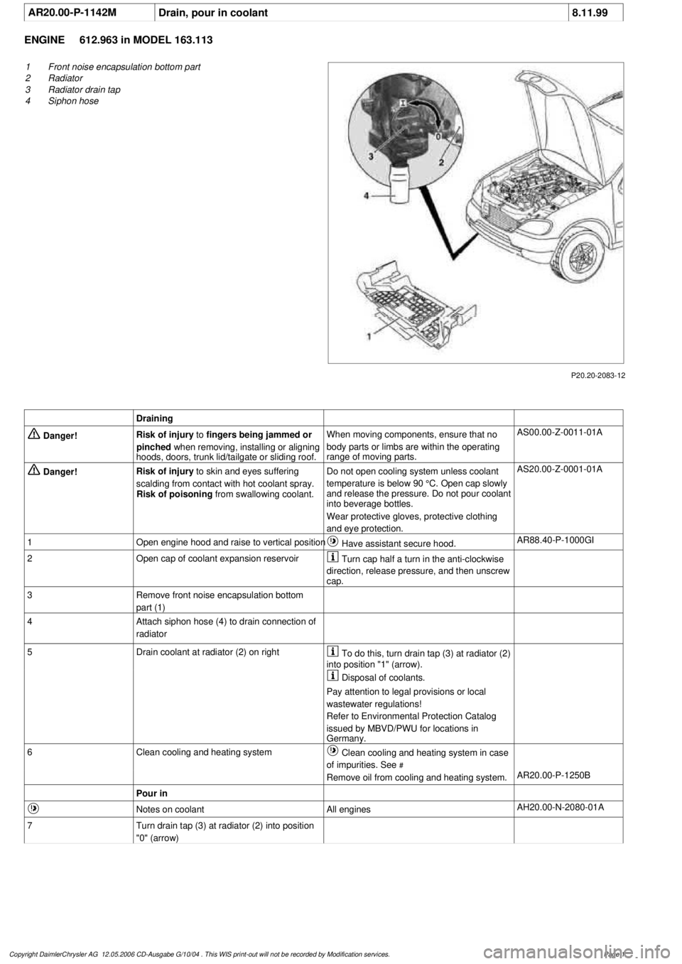
AR20.00-P-1142M
Drain, pour in coolant
8.11.99
ENGINE
612.963 in MODEL 163.113
P20.20-2083-12
1
Front noise encapsulation bottom part
2
Radiator
3
Radiator drain tap
4
Siphon hose
Draining
Danger!
Risk of injury
to
fingers being jammed or
pinched
when removing, installing or aligning
hoods, doors, trunk lid/tailgate or sliding roof.
When moving components, ensure that no
body parts or limbs are within the operating
range of moving parts.
AS00.00-Z-0011-01A
Danger!
Risk of injury
to skin and eyes suffering
scalding from contact with hot coolant spray.
Risk of poisoning
from swallowing coolant.
Do not open cooling system unless coolant
temperature is below 90 °C. Open cap slowly
and release the pressure. Do not pour coolant
into beverage bottles.
Wear protective gloves, protective clothing
and eye protection.
AS20.00-Z-0001-01A
1
Open engine hood and raise to vertical position
Have assistant secure hood.
AR88.40-P-1000GI
2
Open cap of coolant expansion reservoir
Turn cap half a turn in the anti-clockwise
direction, release pressure, and then unscrew
cap.
3
Remove front noise encapsulation bottom
part (1)
4
Attach siphon hose (4) to drain connection of
radiator
5
Drain coolant at radiator (2) on right
To do this, turn drain tap (3) at radiator (2)
into position "1" (arrow).
Disposal of coolants.
Pay attention to legal provisions or local
wastewater regulations!
Refer to Environmental Protection Catalog
issued by MBVD/PWU for locations in
Germany.
6
Clean cooling and heating system
Clean cooling and heating system in case
of impurities. See
#
Remove oil from cooling and heating system.
AR20.00-P-1250B
Pour in
Notes on coolant
All engines
AH20.00-N-2080-01A
7
Turn drain tap (3) at radiator (2) into position
"0" (arrow)
Copyright DaimlerChrysler AG 12.05.2006 CD-Ausgabe G/10/04 . This WIS print-out will not be recorde
d by Modification services.
Page 1
Page 2069 of 4133

Danger!
Risk of accident
caused by vehicle starting
off by itself when engine is running.
Risk of
injury
caused by contusions and burns when
working in engine during starting procedure
Secure vehicle to prevent it from moving.
Wear closed and snug-fitting work clothes.
Do not grasp hot or rotating parts.
AS00.00-Z-0005-01A
8
Pour in coolant
Warm up engine by running at moderate
revs. Top up coolant constantly at coolant
expansion reservoir. Close coolant expansion
tank once
coolant temperature is 60-70 °C.
*BF20.00-P-1001-02E
Note on coolant level
Model 124, 129, 140, 163.113, 168, 170, 202,
208, 210, 220, 463
AH20.00-P-1142-01A
9
Inspect cooling system for leaks
AR20.00-P-1010HA
Cooling system
Number
Designation
Engine
612.963
BF20.00-P-1001-02E
Cooling system
Total capacity
Liter
Y
11.0
Filling capacity of anticorrosion/
antifreeze agent down to
-37 °C
Liter
Y
5.5
Filling capacity of anticorrosion/
antifreeze up to -45 °C
Liter
Y
6.25
Specifications for Operating
Fluids
SheetBB00.40-P-0310-01A
SheetBB00.40-P-0325-00A
Copyright DaimlerChrysler AG 12.05.2006 CD-Ausgabe G/10/04 . This WIS print-out will not be recorde
d by Modification services.
Page 2
Page 2070 of 4133
AR20.00-P-1142HA
Draining and pouring in coolant
2.4.93
ENGINE
112 in MODELS 129, 163, 202, 208, 210, 211.061 /065 /261 /265 /080 /280 /082 /282, 220, 230.467
ENGINE
113 in MODELS 129, 163, 202, 208, 210, 211.070 /083 /283, 215, 220
ENGINE
113.962 in MODELS 463.206 /240 /241 /247 /248 /249 /254
ENGINE
112.945 in MODELS 463.209 /232 /233 /244 /245 /250
ENGINE
137 in MODELS 215, 220
ENGINE
113.982 in MODELS 463.241 /243 /246
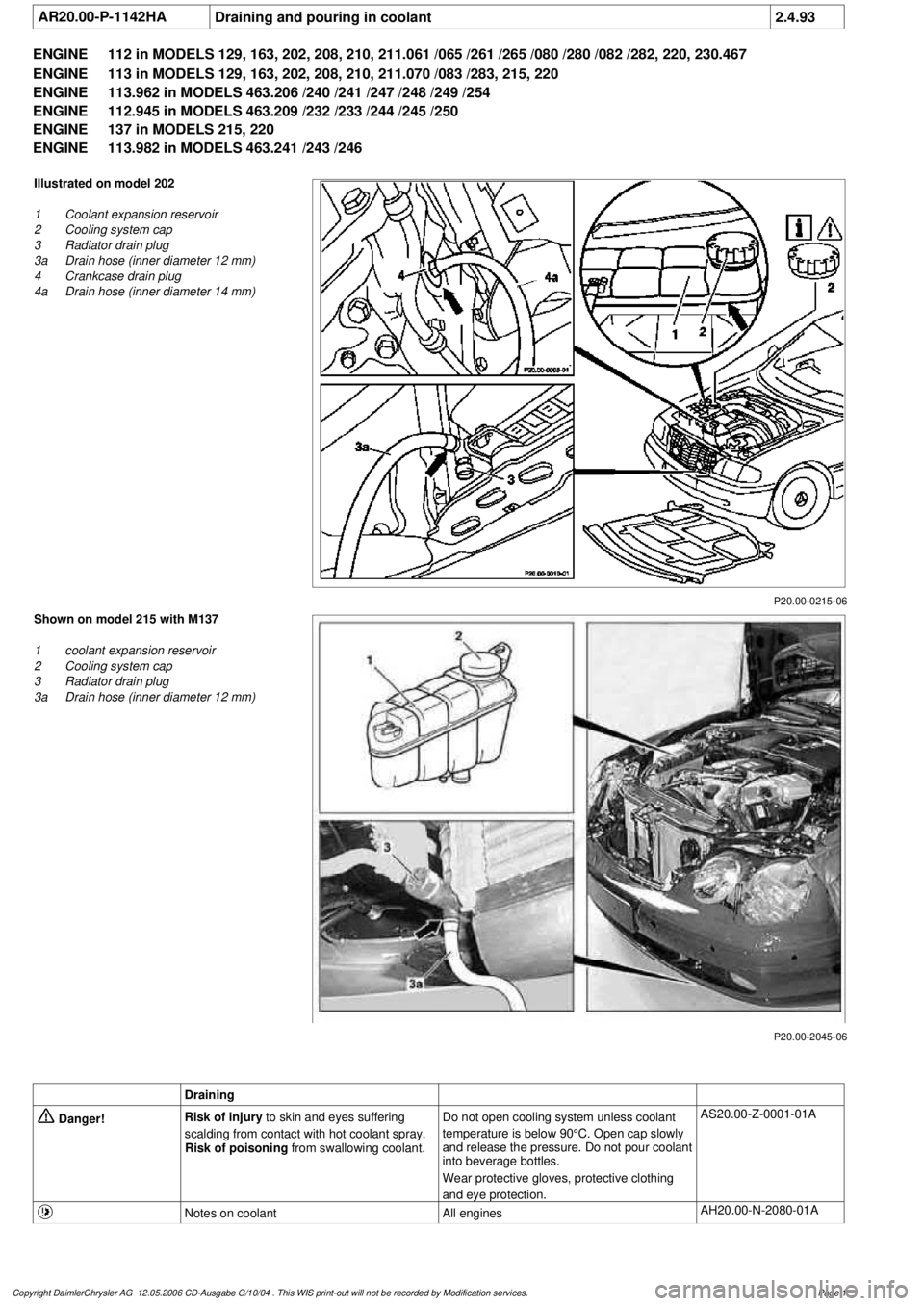
P20.00-0215-06
Illustrated on model 202
1
Coolant expansion reservoir
2
Cooling system cap
3
Radiator drain plug
3a
Drain hose (inner diameter 12 mm)
4
Crankcase drain plug
4a
Drain hose (inner diameter 14 mm)
P20.00-2045-06
Shown on model 215 with M137
1
coolant expansion reservoir
2
Cooling system cap
3
Radiator drain plug
3a
Drain hose (inner diameter 12 mm)
Draining
Danger!
Risk of injury
to skin and eyes suffering
scalding from contact with hot coolant spray.
Risk of poisoning
from swallowing coolant.
Do not open cooling system unless coolant
temperature is below 90°C. Open cap slowly
and release the pressure. Do not pour coolant
into beverage bottles.
Wear protective gloves, protective clothing
and eye protection.
AS20.00-Z-0001-01A
Notes on coolant
All engines
AH20.00-N-2080-01A
Copyright DaimlerChrysler AG 12.05.2006 CD-Ausgabe G/10/04 . This WIS print-out will not be recorde
d by Modification services.
Page 1