Page 2465 of 4133
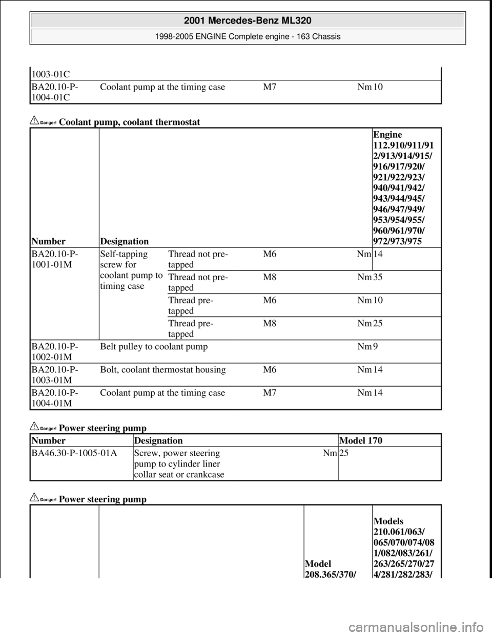
Coolant pump, coolant thermostat
Power steering pump
Power steering pump
1003-01C
BA20.10-P-
1004-01CCoolant pump at the timing caseM7Nm10
NumberDesignation
Engine
112.910/911/91
2/913/914/915/
916/917/920/
921/922/923/
940/941/942/
943/944/945/
946/947/949/
953/954/955/
960/961/970/
972/973/975
BA20.10-P-
1001-01MSelf-tapping
screw for
coolant pump to
timing caseThread not pre-
tappedM6Nm14
Thread not pre-
tappedM8Nm35
Thread pre-
tappedM6Nm10
Thread pre-
tappedM8Nm25
BA20.10-P-
1002-01MBelt pulley to coolant pumpNm9
BA20.10-P-
1003-01MBolt, coolant thermostat housingM6Nm14
BA20.10-P-
1004-01MCoolant pump at the timing caseM7Nm14
NumberDesignationModel 170
BA46.30-P-1005-01AScrew, power steering
pump to cylinder liner
collar seat or crankcaseNm25
Model
208.365/370/
Models
210.061/063/
065/070/074/08
1/082/083/261/
263/265/270/27
4/281/282/283/
2001 Mercedes-Benz ML320
1998-2005 ENGINE Complete engine - 163 Chassis
me
Saturday, October 02, 2010 3:17:57 PMPage 109 © 2006 Mitchell Repair Information Company, LLC.
Page 2466 of 4133
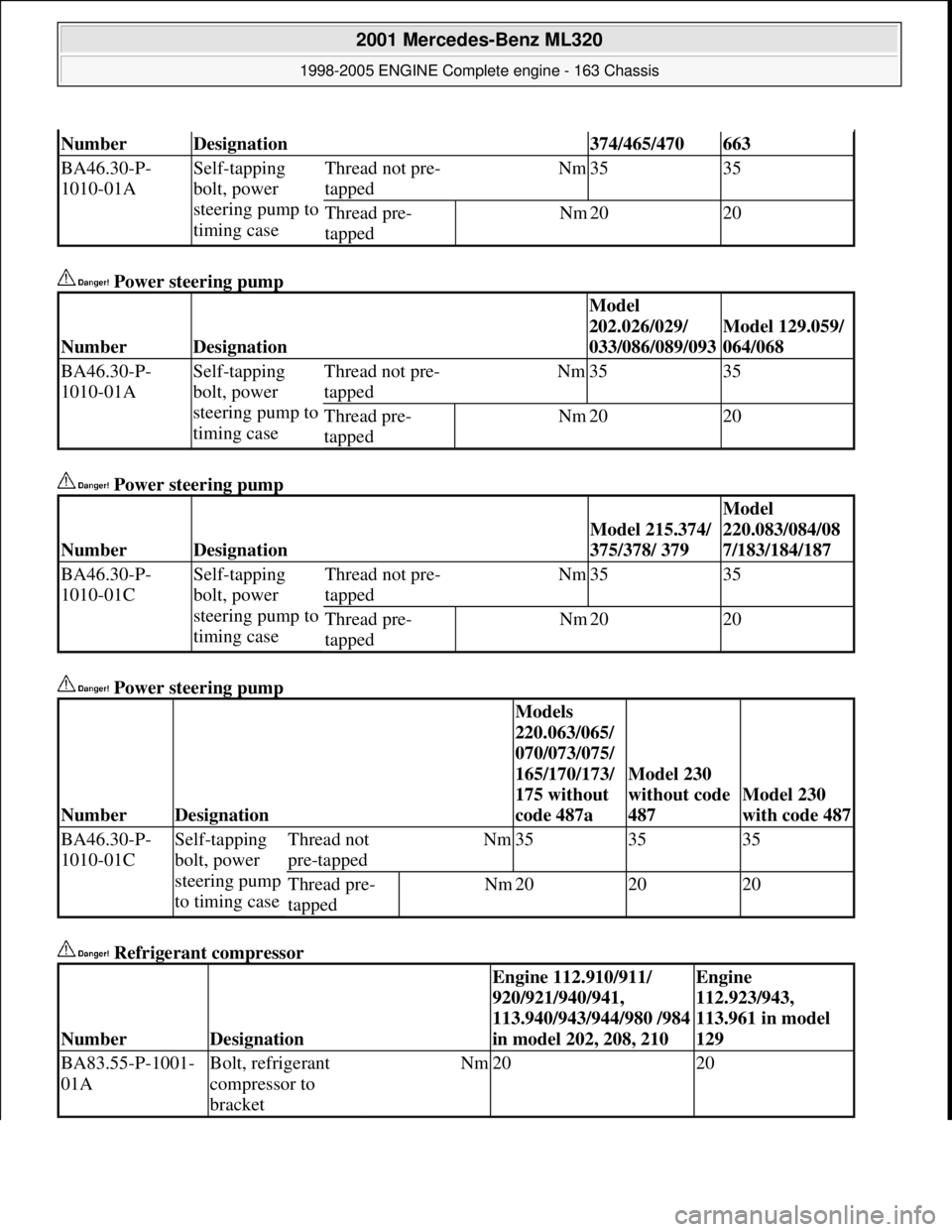
Power steering pump
Power steering pump
Power steering pump
Refrigerant compressor
NumberDesignation374/465/470663
BA46.30-P-
1010-01ASelf-tapping
bolt, power
steering pump to
timing caseThread not pre-
tappedNm3535
Thread pre-
tappedNm2020
NumberDesignation
Model
202.026/029/
033/086/089/093
Model 129.059/
064/068
BA46.30-P-
1010-01ASelf-tapping
bolt, power
steering pump to
timing caseThread not pre-
tappedNm3535
Thread pre-
tappedNm2020
NumberDesignation
Model 215.374/
375/378/ 379
Model
220.083/084/08
7/183/184/187
BA46.30-P-
1010-01CSelf-tapping
bolt, power
steering pump to
timing caseThread not pre-
tappedNm3535
Thread pre-
tappedNm2020
NumberDesignation
Models
220.063/065/
070/073/075/
165/170/173/
175 without
code 487a
Model 230
without code
487
Model 230
with code 487
BA46.30-P-
1010-01CSelf-tapping
bolt, power
steering pump
to timing caseThread not
pre-tappedNm353535
Thread pre-
tappedNm202020
NumberDesignation
Engine 112.910/911/
920/921/940/941,
113.940/943/944/980 /984
in model 202, 208, 210Engine
112.923/943,
113.961 in model
129
BA83.55-P-1001-
01ABolt, refrigerant
compressor to
bracketNm2020
2001 Mercedes-Benz ML320
1998-2005 ENGINE Complete engine - 163 Chassis
me
Saturday, October 02, 2010 3:17:57 PMPage 110 © 2006 Mitchell Repair Information Company, LLC.
Page 2490 of 4133
Shown on engine 112
Fig. 108: Identifying Bottom Part Of Oil Pan Remove/Install Components
- Shown On Engine 112
Remove/install
External torx setFig. 49
1Remove engine trim panel
2Remove viscous fan (4) Right-hand thread!AR20.40-P-5660C
3.1Remove fan shroud (5) Only engine
112.942 /970.
Unscrew bolts (8) at
bottom of fan shroud.
4.1Remove air guide (9) Engine 113.942 only.
5Drain and collect engine oil *BA01.45-P-1003-01B
*BF18.00-P-1001-01H
6Unscrew nuts (7) at front
suspension carrier Before unbolting the
left engine mount, press
oil line of power steering
out of fixture.
*BA22.10-P-1001-01L
7Remove resonance tube (3)
with resonance unit (2) Do not damage the
plastic strap.
The resonance pipe is
attached at the rear at the
2001 Mercedes-Benz ML320
1998-2005 ENGINE Complete engine - 163 Chassis
me
Saturday, October 02, 2010 3:17:58 PMPage 134 © 2006 Mitchell Repair Information Company, LLC.
Page 2494 of 4133
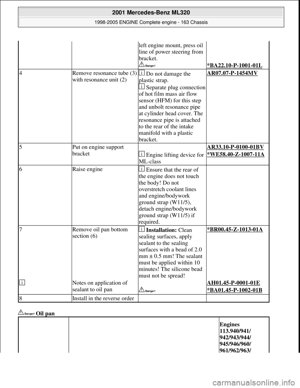
Oil pan
left engine mount, press oil
line of power steering from
bracket.
*BA22.10-P-1001-01L
4Remove resonance tube (3)
with resonance unit (2) Do not damage the
plastic strap.
Separate plug connection
of hot film mass air flow
sensor (HFM) for this step
and unbolt resonance pipe
at cylinder head cover. The
resonance pipe is attached
to the rear of the intake
manifold with a plastic
bracket.AR07.07-P-1454MV
5Put on engine support
bracket AR33.10-P-0100-01BV
Engine lifting device for
ML-class*WE58.40-Z-1007-11A
6Raise engine Ensure that the rear of
the engine does not touch
the body! Do not
overstretch coolant lines
and engine/bodywork
ground strap (W11/5),
detach engine/bodywork
ground strap (W11/5) if
required.
7Remove oil pan bottom
section (6) Installation: Clean
sealing surfaces, apply
sealant to the sealing
surfaces with a bead of 2.0
mm ± 0.5 mm! The sealant
must be applied within 10
minutes! The silicone bead
must not be spread!*BR00.45-Z-1013-01A
Notes on application of
sealant to oil pan AH01.45-P-0001-01E
*BA01.45-P-1002-01B
8Install in the reverse order
Engines
113.940/941/
942/943/944/
945/946/960/
961/962/963/
2001 Mercedes-Benz ML320
1998-2005 ENGINE Complete engine - 163 Chassis
me
Saturday, October 02, 2010 3:17:58 PMPage 138 © 2006 Mitchell Repair Information Company, LLC.
Page 2524 of 4133
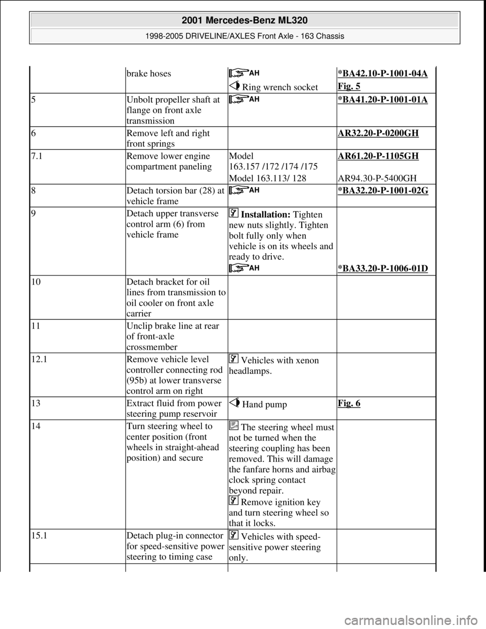
brake hoses *BA42.10-P-1001-04A
Ring wrench socketFig. 5
5Unbolt propeller shaft at
flange on front axle
transmission *BA41.20-P-1001-01A
6Remove left and right
front springs AR32.20-P-0200GH
7.1Remove lower engine
compartment panelingModel
163.157 /172 /174 /175AR61.20-P-1105GH
Model 163.113/ 128AR94.30-P-5400GH
8Detach torsion bar (28) at
vehicle frame *BA32.20-P-1001-02G
9Detach upper transverse
control arm (6) from
vehicle frame Installation: Tighten
new nuts slightly. Tighten
bolt fully only when
vehicle is on its wheels and
ready to drive.
*BA33.20-P-1006-01D
10Detach bracket for oil
lines from transmission to
oil cooler on front axle
carrier
11Unclip brake line at rear
of front-axle
crossmember
12.1Remove vehicle level
controller connecting rod
(95b) at lower transverse
control arm on right Vehicles with xenon
headlamps.
13Extract fluid from power
steering pump reservoir Hand pumpFig. 6
14Turn steering wheel to
center position (front
wheels in straight-ahead
position) and secureThe steering wheel must
not be turned when the
steering coupling has been
removed. This will damage
the fanfare horns and airbag
clock spring contact
beyond repair.
Remove ignition key
and turn steering wheel so
that it locks.
15.1Detach plug-in connector
for speed-sensitive power
steering to timing case Vehicles with speed-
sensitive power steering
only.
2001 Mercedes-Benz ML320
1998-2005 DRIVELINE/AXLES Front Axle - 163 Chassis
me
Saturday, October 02, 2010 3:38:21 PMPage 5 © 2006 Mitchell Repair Information Company, LLC.
Page 2526 of 4133
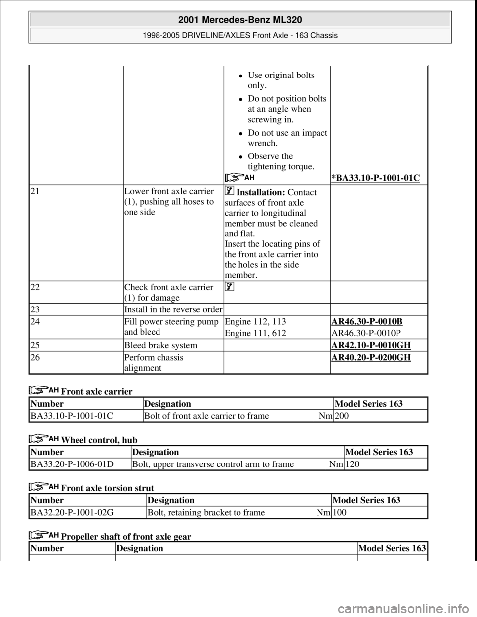
Front axle carrier
Wheel control, hub
Front axle torsion strut
Propeller shaft of front axle gear
Use original bolts
only.
Do not position bolts
at an angle when
screwing in.
Do not use an impact
wrench.
Observe the
tightening torque.
*BA33.10-P-1001-01C
21Lower front axle carrier
(1), pushing all hoses to
one side Installation: Contact
surfaces of front axle
carrier to longitudinal
member must be cleaned
and flat.
Insert the locating pins of
the front axle carrier into
the holes in the side
member.
22Check front axle carrier
(1) for damage
23Install in the reverse order
24Fill power steering pump
and bleedEngine 112, 113AR46.30-P-0010B
Engine 111, 612AR46.30-P-0010P
25Bleed brake system AR42.10-P-0010GH
26Perform chassis
alignment AR40.20-P-0200GH
NumberDesignationModel Series 163
BA33.10-P-1001-01CBolt of front axle carrier to frameNm200
NumberDesignationModel Series 163
BA33.20-P-1006-01DBolt, upper transverse control arm to frameNm120
NumberDesignationModel Series 163
BA32.20-P-1001-02GBolt, retaining bracket to frameNm100
NumberDesignationModel Series 163
2001 Mercedes-Benz ML320
1998-2005 DRIVELINE/AXLES Front Axle - 163 Chassis
me
Saturday, October 02, 2010 3:38:21 PMPage 7 © 2006 Mitchell Repair Information Company, LLC.
Page 3039 of 4133
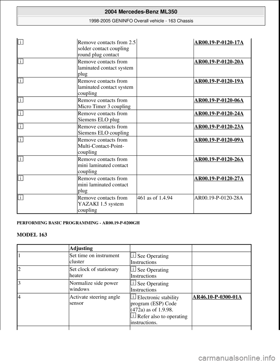
PERFORMING BASIC PROGRAMMING - AR00.19-P-0200GH
MODEL 163
Remove contacts from 2.5
solder contact coupling
round plug contact AR00.19-P-0120-17A
Remove contacts from
laminated contact system
plug AR00.19-P-0120-20A
Remove contacts from
laminated contact system
coupling AR00.19-P-0120-19A
Remove contacts from
Micro Timer 3 coupling AR00.19-P-0120-06A
Remove contacts from
Siemens ELO plug AR00.19-P-0120-24A
Remove contacts from
Siemens ELO coupling AR00.19-P-0120-23A
Remove contacts from
Multi-Contact-Point-
coupling AR00.19-P-0120-09A
Remove contacts from
mini laminated contact
coupling AR00.19-P-0120-26A
Remove contacts from
mini laminated contact
plug AR00.19-P-0120-27A
Remove contacts from
YAZAKI 1.5 system
coupling461 as of 1.4.94AR00.19-P-0120-28A
Adjusting
1Set time on instrument
cluster See Operating
Instructions
2Set clock of stationary
heater See Operating
Instructions
3Normalize side power
windows See Operating
Instructions
4Activate steering angle
sensor Electronic stability
program (ESP) Code
(472a) as of 1.9.98.
Refer also to operating
instructions.AR46.10-P-0300-01A
2004 Mercedes-Benz ML350
1998-2005 GENINFO Overall vehicle - 163 Chassis
me
Saturday, October 02, 2010 3:47:52 PMPage 394 © 2006 Mitchell Repair Information Company, LLC.
Page 3049 of 4133
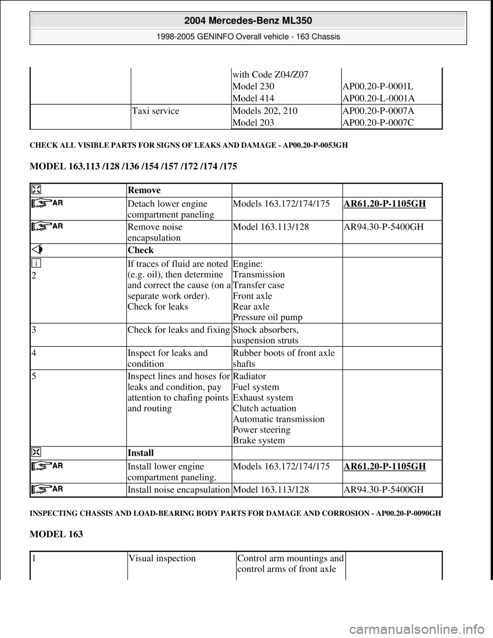
CHECK ALL VISIBLE PARTS FOR SIGNS OF LEAKS AND DAMAGE - AP00.20-P-0053GH
MODEL 163.113 /128 /136 /154 /157 /172 /174 /175
INSPECTING CHASSIS AND LOAD-BEARING BODY PARTS FOR DAMAGE AND CORROSION - AP00.20-P-0090GH
MODEL 163
with Code Z04/Z07
Model 230AP00.20-P-0001L
Model 414AP00.20-L-0001A
Taxi serviceModels 202, 210AP00.20-P-0007A
Model 203AP00.20-P-0007C
Remove
Detach lower engine
compartment panelingModels 163.172/174/175AR61.20-P-1105GH
Remove noise
encapsulationModel 163.113/128AR94.30-P-5400GH
Check
2If traces of fluid are noted
(e.g. oil), then determine
and correct the cause (on a
separate work order).
Check for leaksEngine:
Transmission
Transfer case
Front axle
Rear axle
Pressure oil pump
3Check for leaks and fixingShock absorbers,
suspension struts
4Inspect for leaks and
conditionRubber boots of front axle
shafts
5Inspect lines and hoses for
leaks and condition, pay
attention to chafing points
and routingRadiator
Fuel system
Exhaust system
Clutch actuation
Automatic transmission
Power steering
Brake system
Install
Install lower engine
compartment paneling.Models 163.172/174/175AR61.20-P-1105GH
Install noise encapsulationModel 163.113/128AR94.30-P-5400GH
1Visual inspectionControl arm mountings and
control arms of front axle
2004 Mercedes-Benz ML350
1998-2005 GENINFO Overall vehicle - 163 Chassis
me
Saturday, October 02, 2010 3:47:52 PMPage 404 © 2006 Mitchell Repair Information Company, LLC.