1997 MERCEDES-BENZ ML350 power steering
[x] Cancel search: power steeringPage 1549 of 4133
REAR WASH - FUNCTION - GF82.35-P-3001GH
MODEL 163
The rear wash function is activated by placing the rear wiper/ washer switch (S78) in the down position. The
switch contact connects the tailgate washer pump (M5/3) to terminal 15. The All Activity Module (AAM)
(N10) detects the activation of the switch via the second switch contact and actuates the tailgate washer motor
(M6/4) and the tailgate washer fluid pump (M5/3) for as long as the switch is on.
The activation time for the tailgate washer fluid pump (M5/3)is limited to 15 sec. To reactivate the pump, the
button must be pressed again.
To wipe window dry, the tailgate wiper motor (M6/4) remains activated for five seconds after the switch is
released.
As described for the rear wiper function, a relay circuit in the wiper motor stops the wiper in the park position .
WINDSHIELD WASH - FUNCTION - GF82.35-P-3002GH
MODEL 163
The windshield wash function is activated by pulling the combination switch, washer switch (S4s4) towards
the steering column. The switch contact connects the washer pump (M5/1) to terminal 15R. The All Activity
Module (AAM) (N10) detects switch activation via an input that measures power supply to the washer pump
(M5/1).
If the combination switch (S4) is in the Wiper Off or Intermittent position, the AAM activates the wiper
motor (M6/1) via rela
y F1k17 . To wipe windshield dry, the motor continues to operate after the switch has
Rear window washer
pump, location /
purpose / design /
function GF82.35-P-4103GH
Table of contents,
function description,
wiper system (WS) GF82.30-P-0998GH
Rear Wipe GF82.30-P-3004GH
Rear Wiper/Washer
Switch GF82.30-P-4105GH
Tailgate Wiper Motor GF82.30-P-4106GH
Tailgate Washer Pump GF82.35-P-4103GH
All Activity ModuleTo 30.11.99GF54.21-P-4100GH
As of 1.12.99GF54.21-P-4100GK
2001 Mercedes-Benz ML320
1998-2005 ACCESSORIES & BODY, CAB Electrical System - Body - 163 Chassis
me
Saturday, October 02, 2010 3:30:05 PMPage 54 © 2006 Mitchell Repair Information Company, LLC.
Page 1569 of 4133
4-channel power amplifier for vehicle loudspeakers
System interlinkage
The radio and navigation unit (A2/56) is provided with the following components for data exchange with
external digital components:
CAN (A1 -A2/56)
The radio and navigation unit (A2/56) is connected with the instrument cluster (A1) via a separate
CAN bus. The difference to the other CAN systems is indicated by the spelling CAN bus (A1-A2/56).
The CAN bus (A1-A2/56) allows the following functions:
Operation of the radio and navigation unit (A2/56)is also possible with the multifunction steering
wheel.
The multifunction display (A1/p13) in the instrument cluster (A1) can display navigation
information on the current operating status of the radio and navigation unit (A2/56) .
The connection to the CAN bus (A1-A2/56) is only realized on models 208 and 210. (Status 3/99)
Digital data bus (D2B)
Data can be exchanged between the external audio components, the telephone system and - if present -
the voice control system over the D2B bus. This allows control data as well as the actual audio signals
(e.g. music from CD changer) to be transferred.
The only additional D2B component presently possible is the CD changer (A2/6) (Status: 3/99)
K bus (diagnostic interface)
Data exchange is accomplished between the diagnostic interface and the hand-held tester (reading out
DTCs and actual values, ...).
The communication between the HHT and all other D2B components is accomplished over the radio
and navigation unit (A2/56) diagnostic interface.
Audio 30 APS, location of
componentsModel 163GF82.61-P-0002-01D
Model 168GF82.61-P-0002-01B
Model 170GF82.61-P-0002-01A
Model 208, model 210&.2.(GF82.61-P-0002-
01C)
Audio 30 APS block
diagramModel 163GF82.61-P-0002-02D
Model 168GF82.61-P-0002-02B
2001 Mercedes-Benz ML320
1998-2005 ACCESSORIES & BODY, CAB Electrical System - Body - 163 Chassis
me
Saturday, October 02, 2010 3:30:05 PMPage 74 © 2006 Mitchell Repair Information Company, LLC.
Page 1662 of 4133
MODEL 163.113/136/154/172 With 5 L reservoir
INSTALLING SOUND SYSTEM JUMPER HARNESS - AF82.60-P-1010-01AG
1. Insert sound system jumper harness through radio opening
Position jumper harness within cockpit assembly so that jumper harness is routed above HVAC
venturi tube and lays across base of steering column.
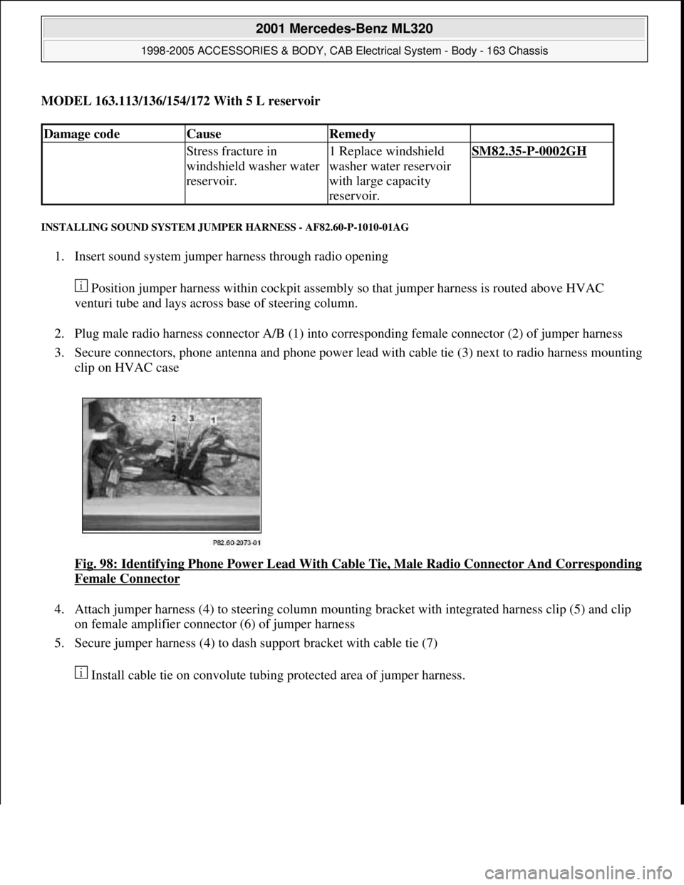
2. Plug male radio harness connector A/B (1) into corresponding female connector (2) of jumper harness
3. Secure connectors, phone antenna and phone power lead with cable tie (3) next to radio harness mounting
clip on HVAC case
Fi
g. 98: Identifying Phone Power Lead With Cable Tie, Male Radio Connector And Corresponding
Female Connector
4. Attach jumper harness (4) to steering column mounting bracket with integrated harness clip (5) and clip
on female amplifier connector (6) of jumper harness
5. Secure jumper harness (4) to dash support bracket with cable tie (7)
Install cable tie on convolute tubin
g protected area of jumper harness.
Damage codeCauseRemedy
Stress fracture in
windshield washer water
reservoir.1 Replace windshield
washer water reservoir
with large capacity
reservoir.SM82.35-P-0002GH
2001 Mercedes-Benz ML320
1998-2005 ACCESSORIES & BODY, CAB Electrical System - Body - 163 Chassis
me
Saturday, October 02, 2010 3:30:06 PMPage 167 © 2006 Mitchell Repair Information Company, LLC.
Page 2042 of 4133
3. Normalize side power windows. See NORMALIZING POWER WINDOWS .
4. Start engine and run at idle. Turn steering wheel from one lock position to the other to activate steering
angle sensor. Center steering wheel. Message "EI. STAB. PROGRAM GO TO GARAGE" should erase
from multifunction display panel.
5. If equipped, normalize tilting/sliding roof. See NORMALIZING TILTING/SLIDING ROOF
.
6. If equipped, normalize memory power seats, steering column and outside mirror if components are
installed. See NORMALIZING MEMORY POWER SEATS, STEERING COLUMN & OUTSIDE
MIRROR .
Normalizing Power Windows
1. Completely close each window with manual switch. Hold switch in closed position for .3 second.
2. Repeat procedure for each power window.
Normalizing Memory Power Seats, Steering Column & Outside Mirror
1. Using manual switch, move seat to each end position and hold for .3 second. Repeat procedure for each
switch except rear stop of backrest.
2. Repeat procedure for end positions of steering wheel and outside mirrors.
Normalizing Tilting/Sliding Roof
Open roof with SR switch until mechanical stop is reached. Continue to press switch for .5 seconds.
Setting Time
1. Use bottom left button on steering wheel to scroll through menus on instrument cluster to "Settings"
menu.
2. Move selection marker with + or - button to "Time" submenu.
3. Press up or down arrows to "Clock, hours" setting. Confirm selection marker is on the hour setting.
4. Press + or - to set hour. Press reset knob in instrument cluster to confirm.
5. Move selection marker with + or - button to "Time" submenu.
6. Press up or down arrows to "Clock, minutes" setting. Confirm selection marker is on the minutes setting.
7. Press + or - to set minute. Press reset knob in instrument cluster to confirm.
TESTING
If generator malfunctions, check for Diagnostic Trouble Codes (DTCs) in Motor Electronics Sequential Fuel
Injection (ME-SFI) system. See appropriate SELF-DIAGNOSTICS article in ENGINE PERFORMANCE. If
cause of generator malfunction is not engine performance related, replace generator.
RETRIEVING & ERASING DIAGNOSTIC TROUBLE CODES
NOTE: Before replacing any component that scan tool suggests are faulty, ensure that
all wiring connections and harness connectors are okay. Ensure that power and
2001 Mercedes-Benz ML320
2001-04 STARTING & CHARGING SYSTEMS Generators & Regulators - 163 Chassis
me
Saturday, October 02, 2010 3:20:32 PMPage 8 © 2006 Mitchell Repair Information Company, LLC.
Page 2411 of 4133
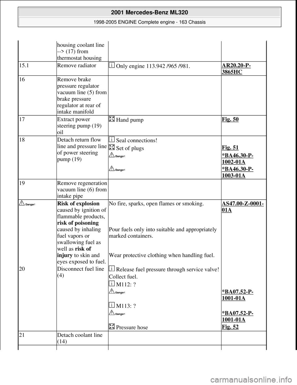
housing coolant line
--> (17) from
thermostat housing
15.1Remove radiator Only engine 113.942 /965 /981.AR20.20-P-
3865HC
16Remove brake
pressure regulator
vacuum line (5) from
brake pressure
regulator at rear of
intake manifold
17Extract power
steering pump (19)
oil Hand pumpFig. 50
18Detach return flow
line and pressure line
of power steering
pump (19) Seal connections!
Set of plugsFig. 51
*BA46.30-P-
1002-01A
*BA46.30-P-
1003-01A
19Remove regeneration
vacuum line (6) from
intake pipe
Risk of explosion
caused by ignition of
flammable products,
risk of poisoning
caused by inhaling
fuel vapors or
swallowing fuel as
well as risk of
injury to skin and
eyes exposed to fuel.No fire, sparks, ope n flames or smoking.AS47.00-Z-0001-
01A
Pour fuels only into suitable and appropriately
marked containers.
Wear protective clothing when handling fuel.
20Disconnect fuel line
(4) Release fuel pressure through service valve!
Collect fuel.
M112: ?
*BA07.52-P-
1001-01A
M113: ?
*BA07.52-P-
1001-01A
Pressure hoseFig. 52
21Detach coolant line
(14)
2001 Mercedes-Benz ML320
1998-2005 ENGINE Complete engine - 163 Chassis
me
Saturday, October 02, 2010 3:17:56 PMPage 55 © 2006 Mitchell Repair Information Company, LLC.
Page 2415 of 4133
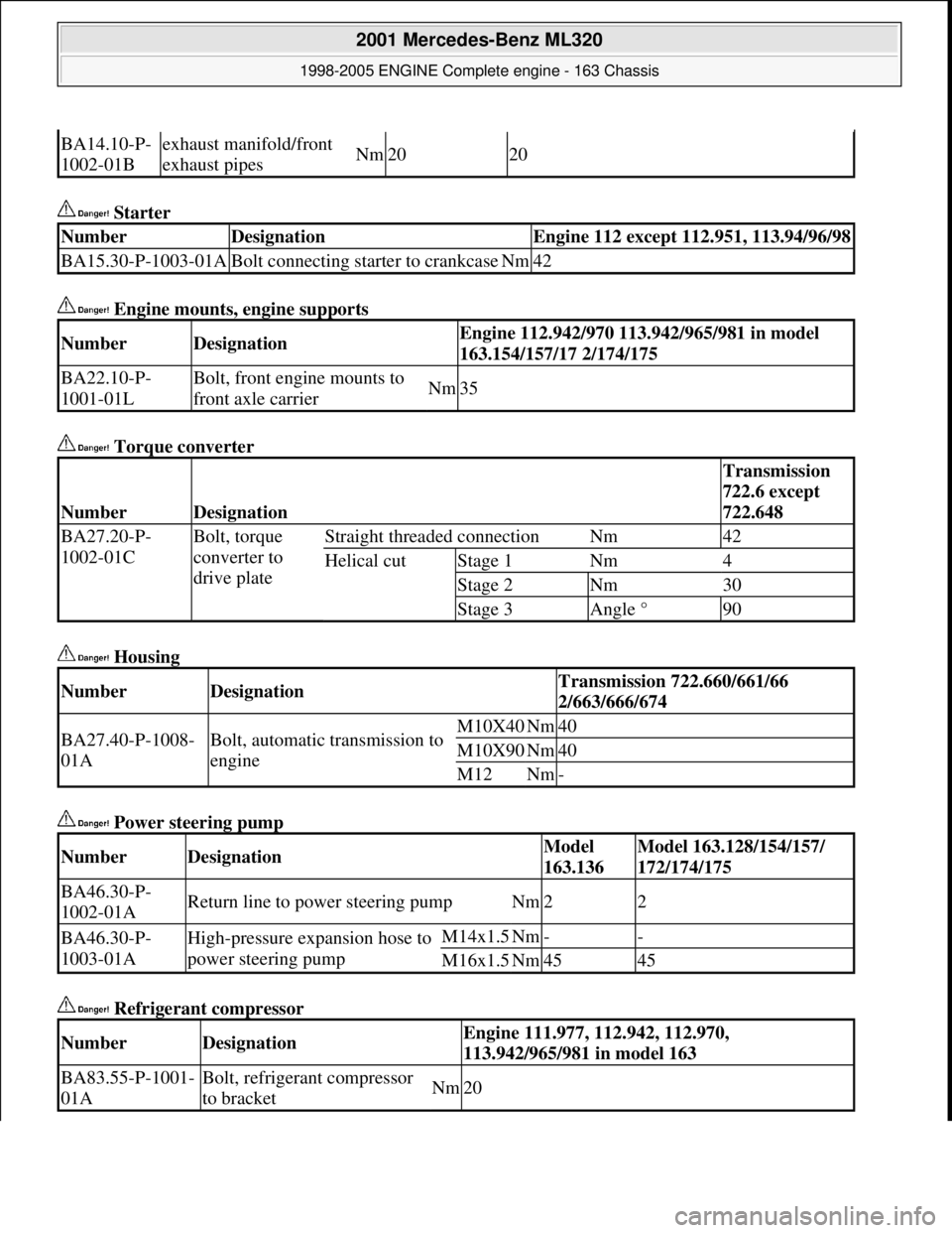
Starter
Engine mounts, engine supports
Torque converter
Housing
Power steering pump
Refrigerant compressor
BA14.10-P-
1002-01Bexhaust manifold/front
exhaust pipesNm2020
NumberDesignationEngine 112 except 112.951, 113.94/96/98
BA15.30-P-1003-01ABolt connecting starter to crankcaseNm42
NumberDesignationEngine 112.942/970 113.942/965/981 in model
163.154/157/17 2/174/175
BA22.10-P-
1001-01LBolt, front engine mounts to
front axle carrierNm35
NumberDesignation
Transmission
722.6 except
722.648
BA27.20-P-
1002-01CBolt, torque
converter to
drive plateStraight threaded connectionNm42
Helical cutStage 1Nm4
Stage 2Nm30
Stage 3Angle °90
NumberDesignationTransmission 722.660/661/66
2/663/666/674
BA27.40-P-1008-
01ABolt, automatic transmission to
engineM10X40Nm40
M10X90Nm40
M12Nm-
NumberDesignationModel
163.136Model 163.128/154/157/
172/174/175
BA46.30-P-
1002-01AReturn line to power steering pumpNm22
BA46.30-P-
1003-01AHigh-pressure expansion hose to
power steering pumpM14x1.5Nm--
M16x1.5Nm4545
NumberDesignationEngine 111.977, 112.942, 112.970,
113.942/965/981 in model 163
BA83.55-P-1001-
01ABolt, refrigerant compressor
to bracketNm20
2001 Mercedes-Benz ML320
1998-2005 ENGINE Complete engine - 163 Chassis
me
Saturday, October 02, 2010 3:17:56 PMPage 59 © 2006 Mitchell Repair Information Company, LLC.
Page 2459 of 4133
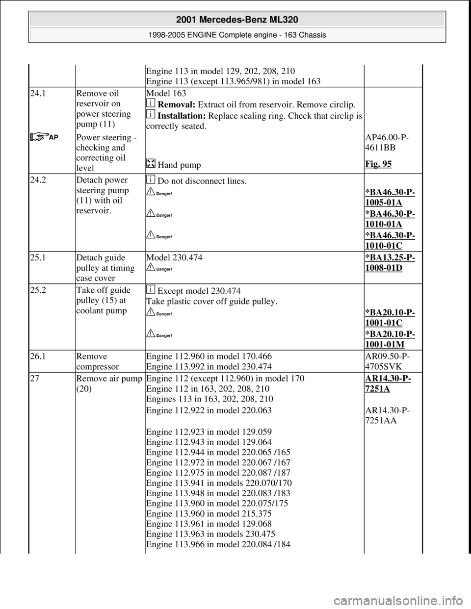
Engine 113 in model 129, 202, 208, 210
Engine 113 (except 113.965/981) in model 163
24.1Remove oil
reservoir on
power steering
pump (11)Model 163
Removal: Extract oil from rese rvoir. Remove circlip.
Installation: Replace sealing ring. Ch eck that circlip is
correctly seated.
Power steering -
checking and
correcting oil
level AP46.00-P-
4611BB
Hand pumpFig. 95
24.2Detach power
steering pump
(11) with oil
reservoir. Do not disconnect lines.
*BA46.30-P-
1005-01A
*BA46.30-P-
1010-01A
*BA46.30-P-
1010-01C
25.1Detach guide
pulley at timing
case coverModel 230.474
*BA13.25-P-
1008-01D
25.2Take off guide
pulley (15) at
coolant pump Except model 230.474
Take plastic cover off guide pulley.
*BA20.10-P-
1001-01C
*BA20.10-P-
1001-01M
26.1Remove
compressorEngine 112.960 in model 170.466
Engine 113.992 in model 230.474AR09.50-P-
4705SVK
27Remove air pump
(20)Engine 112 (except 112.960) in model 170
Engine 112 in 163, 202, 208, 210
Engines 113 in 163, 202, 208, 210AR14.30-P-
7251A
Engine 112.922 in model 220.063AR14.30-P-
7251AA
Engine 112.923 in model 129.059
Engine 112.943 in model 129.064
Engine 112.944 in model 220.065 /165
Engine 112.972 in model 220.067 /167
Engine 112.975 in model 220.087 /187
Engine 113.941 in models 220.070/170
Engine 113.948 in model 220.083 /183
Engine 113.960 in model 220.075/175
Engine 113.960 in model 215.375
Engine 113.961 in model 129.068
Engine 113.963 in models 230.475
Engine 113.966 in model 220.084 /184
2001 Mercedes-Benz ML320
1998-2005 ENGINE Complete engine - 163 Chassis
me
Saturday, October 02, 2010 3:17:57 PMPage 103 © 2006 Mitchell Repair Information Company, LLC.
Page 2460 of 4133
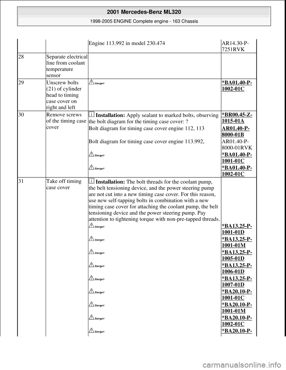
Engine 113.992 in model 230.474AR14.30-P-
7251RVK
28Separate electrical
line from coolant
temperature
sensor
29Unscrew bolts
(21) of cylinder
head to timing
case cover on
right and left *BA01.40-P-
1002-01C
30Remove screws
of the timing case
cover Installation: Apply sealant to marked bolts, observing
the bolt diagram for th e timing case cover: ?*BR00.45-Z-
1015-01A
Bolt diagram for timing case cover engine 112, 113AR01.40-P-
8000-01B
Bolt diagram for timing case cover engine 113.992,AR01.40-P-
8000-01RVK
*BA01.40-P-
1001-01C
*BA01.40-P-
1002-01C
31Take off timing
case cover Installation: The bolt threads for the coolant pump,
the belt tensioning device, and the power steering pump
are not cut into a new timing case cover. For this reason,
use new self-tapping bolts in combination with a new
timing case cover for attaching the coolant pump, the belt
tensioning device and th e power steering pump. Pay
attention to tightening torque with non-pre-tapped threads.
*BA13.25-P-
1001-01D
*BA13.25-P-
1001-01M
*BA13.25-P-
1005-01D
*BA13.25-P-
1006-01D
*BA13.25-P-
1007-01D
*BA20.10-P-
1001-01C
*BA20.10-P-
1001-01M
*BA20.10-P-
1002-01C
*BA20.10-P-
2001 Mercedes-Benz ML320
1998-2005 ENGINE Complete engine - 163 Chassis
me
Saturday, October 02, 2010 3:17:57 PMPage 104 © 2006 Mitchell Repair Information Company, LLC.