1997 MERCEDES-BENZ ML350 power steering
[x] Cancel search: power steeringPage 3757 of 4133

3.1
Remove viscous fan (1)
Engine 112.942 /970 and 113.942.
Right-hand thread!
AR20.40-P-5660C
3.2
Remove electric fan
Only Engine 113.965 /981.
AR20.40-P-5000GH
4.1
Pull off plate clamps of fan shroud (2)
Only for Engine 112.942, from 5/98.
5.1
Remove fan shroud (3)
Only for Engine 112.942 /970 und
113.942. Unscrew the bolts at bottom of fan
shroud for this step
Installation:
If installing a new radiator
with integral power steering pump oil cooler, a
new fan shroud is required if a radiator
without integral oil cooler was previously
installed.
6
Remove headlamp (7).
AR82.10-P-4730GH
7
Remove radiator crossmember (8)
AR62.30-P-2300GH
8
Detach coolant line (4, 6) and expansion
reservoir coolant line (5) at the radiator
Installation:
Replace the hose clamps on
the radiator fitting for the coolant hose, as
they could cause damage to the screw/thread.
Hose clamp
*BA20.20-P-1004-01A
9
Remove the rubber seal on radiator (9)
10.1
Remove oil line (return line of radiator
!
power steering pump expansion reservoir)
(18) and oil line (feed line of steering gear
!
radiator) (19)
From 5/98 only, seal off the connections.
Set of plugs
*129589009100
11
Unscrew ATF lines (10) at the radiator
Seal off the connections.
*BA20.20-P-1001-01A
*BA20.20-P-1003-01A
Set of plugs
*129589009100
12.1
Detach the connector from the fan and
remove the fan grille (11)
Only for Engine 112.942 /970 and 113.942.
13
Unscrew the condenser from the radiator
Do not disconnect the lines.
14
Remove fasteners (20) and damper rubber
(21)
The damper rubber (21) is designed to
prevent possible vibrations between the
condenser and radiator (15) during off-road
driving.
15
Remove air conditioning system fluid
reservoir (14) from the radiator
Place aside with the lines connected.
Detach the condenser from the radiator.
16
Remove radiator (15)
When installing, the spigots on the
radiator must be inserted in the rubber
grommets in the bottom crossmember.
Installation:
On Model 163.154 with
Engine 112.942 before VIN end number
043553, when installing a new radiator with
integral power steering pump oil cooler,
additional operations are required, if they
have not already been carried out:
#
v
Retrofit the bracket for the oil cooler line of
the power steering pump
SM46.30-P-0002A
k
Radiator with integral oil cooler for the power
steering pump
BT20.20-P-0001-01A
17
Detach air guides (12)
Replace the clamps on air guides (13).
18
Install in the reverse order
19
Pour in coolant
AR20.00-P-1142HA
20
Check the headlamp setting and correct if
necessary
e
Check and adjust the headlamp setting
AP82.10-P-8260GH
Danger!
Risk of accident
caused by vehicle starting
off when engine is running.
Risk of injury
caused by contusions and burns when
working in engine during starting procedure
Secure the vehicle to prevent it from moving.
Wear closed and snug-fitting work clothes.
Do not grasp hot or rotating parts.
AS00.00-Z-0005-01A
21
Check the oil level in the automatic
transmission and correct if necessary
AR27.00-P-0101A
22
Check the cooling system for leaks
AR20.00-P-1010HA
Radiator, coolant hoses
Copyright DaimlerChrysler AG 12.05.2006 CD-Ausgabe G/10/04 . This WIS print-out will not be recorde
d by Modification services.
Page 2
Page 3760 of 4133
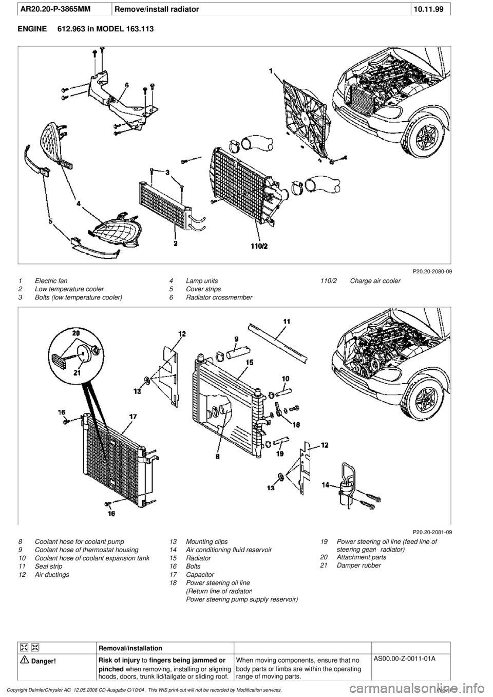
AR20.20-P-3865MM
Remove/install radiator
10.11.99
ENGINE
612.963 in MODEL 163.113
P20.20-2080-09
1
Electric fan
2
Low temperature cooler
3
Bolts (low temperature cooler)
110/2
Charge air cooler
4
Lamp units
5
Cover strips
6
Radiator crossmember
P20.20-2081-09
8
Coolant hose for coolant pump
9
Coolant hose of thermostat housing
10
Coolant hose of coolant expansion tank
11
Seal strip
12
Air ductings
19
Power steering oil line (feed line of
steering gear
!
radiator)
20
Attachment parts
21
Damper rubber
13
Mounting clips
14
Air conditioning fluid reservoir
15
Radiator
16
Bolts
17
Capacitor
18
Power steering oil line
(Return line of radiator
!
Power steering pump supply reservoir)
Removal/installation
Danger!
Risk of injury
to
fingers being jammed or
pinched
when removing, installing or aligning
hoods, doors, trunk lid/tailgate or sliding roof.
When moving components, ensure that no
body parts or limbs are within the operating
range of moving parts.
AS00.00-Z-0011-01A
Copyright DaimlerChrysler AG 12.05.2006 CD-Ausgabe G/10/04 . This WIS print-out will not be recorde
d by Modification services.
Page 1
Page 3761 of 4133

Danger!
Risk of injury
to skin and eyes suffering
scalding from contact with hot coolant spray.
Risk of poisoning
from swallowing coolant.
Do not open cooling system unless coolant
temperature is below 90 °C. Open cap slowly
and release the pressure. Do not pour coolant
into beverage bottles.
Wear protective gloves, protective clothing
and eye protection.
AS20.00-Z-0001-01A
1
Open engine hood and raise to vertical position
Have second person secure hood.
AR88.40-P-1000GI
2
Connect no load current retention unit
*WH58.30-Z-1005-09A
3
Disconnect battery ground cable
AR54.10-P-0003A
4
Remove trim panel of cylinder head cover
AR01.20-P-5014-02B
*BA01.20-P-1002-01A
*BA01.20-P-1003-01A
5
Remove bottom part of noise encapsulation
at front
AR94.30-P-5400GH
6
Remove electric fan (1)
Remove toward bottom.
AR20.40-P-5000M
7
Drain coolant
At radiator.
AR20.00-P-1142M
Notes on coolant
All engines
AH20.00-N-2080-01A
8
Remove charge air cooler (110/2)
AR09.41-P-6817MM
9.1
Attach guard plate for radiator/condenser
With automatic air conditioning, code
581a and AC system or Tempmatic USA,
code 580.
Attach additional AC condenser in the
vehicle.
y
Guard plate for radiator/condenser
Engine 606 in model 124,
Engine 606.961 in model 140,
Engine 112, 113, 604, 605, 611.960 in
MODEL 202,
Engine 602.983, 612.966 in MODEL 461,
Engine 628.962, 612.965, 606.964, 112.945,
113.962/ 982 in MODEL 463,
Engine 111, 112, 611.962, 612.962 in model
203,
Engines 112, 113, 611.961, 612.961, 613.961
in MODEL 210,
Engine 112 in model 170,
Engine 112 in MODEL 220,
Engine 113 in MODEL 211, 215, 220,
Engine 112 in MODEL 208,
Engine 112, 612.963, 628.963 in MODEL 163,
Engine 112.923 /943, 113.961 in MODEL 129,
Engine 137, 275 in MODEL 215, 220,
Engine 613.960, 628.960 in MODEL 220,
Engine 113.992 in model 230.474,
Engine 271 in model 209, 203,
Engine 285.950 in model 240.078 /178,
Engine 612.967 in model 209.316,
Engine 648 in model 220
Engine 112.951 in model 639.601/603/
605/701/703/705/801/803/805
Engine 646.983/984 in model 639.601/
603/605/701/703/705/801/803/805
Engine 646.982 in model
639.601/603/605/701/703/705
WF58.50-P-0110-01A
10
Remove seal rail (11)
11
Extract steering oil from reservoir
Hand pump
*210589007100
12.1
Disconnect power steering oil line (return line
radiator
!
power steering pump supply
reservoir) (18)
Seal connections.
Installation:
Install new sealing rings.
*BA46.30-P-1012-01A
Clamp
*000589543700
Set of stop plugs
*129589009100
12.2
Disconnect power steering oil line (feed line of
steering gear
!
radiator) (19)
Clamp
*000589543700
Set of stop plugs
*129589009100
Hexagon socket wrench
*WH58.30-Z-1001-06A
Hexagon socket wrench
*WH58.30-Z-1002-06A
Copyright DaimlerChrysler AG 12.05.2006 CD-Ausgabe G/10/04 . This WIS print-out will not be recorde
d by Modification services.
Page 2
Page 3762 of 4133

13
Disconnect coolant hose to coolant pump (8),
coolant hose from thermostat housing (9) and
coolant hose from coolant expansion tank
(10) at radiator
Hexagon socket wrench
*WH58.30-Z-1001-06A
Hexagon socket wrench
*WH58.30-Z-1002-06A
14
Detach air guides (12)
Installation:
Replace fastening clamps
(13)
15
Unscrew bolts (16) at condenser (17) to
radiator
Avoid deformation of condenser lines.
Do not disconnect lines.
16
Remove attachment parts (20) and rubber
shock absorber (21)
Installation:
Ensure, that the rubber
shock absorbers do not drop when installing
the radiator.
Replace fastening clamps.
17
Take off fluid reservoir of AC (14) at radiator
Place to the side with lines connected.
External torx set
*001589760900
18
Remove bracket of charge air pipe at left
radiator
Installation:
Insert bracket of charge air
pipe into the bracket at the radiator.
19
Remove radiator (15)
Installation:
When installing, the mounting
studs of the radiator must be inserted into the
rubber grommets of the lower crossmember.
20
Install in the reverse order
21
Check headlamp adjustment, correct if
necessary
e
Check and correct headlamp adjustment
AP82.10-P-8260A
22
Inspect cooling system for leaks
AR20.00-P-1010HA
23
Fill power steering pump and bleed
Danger!
Risk of accident
caused by vehicle starting
off by itself when engine is running.
Risk of
injury
caused by contusions and burns when
working in engine during starting procedure
Secure vehicle to prevent it from moving.
Wear closed and snug-fitting work clothes.
Do not grasp hot or rotating parts.
AS00.00-Z-0005-01A
24
Run engine and inspect for leaks
Crankcase ventilation, cylinder head cover
Number
Designation
Engine
612.963
BA01.20-P-1002-01A
Bolt, cylinder head cover trim panel to
cylinder head cover
Nm
10
BA01.20-P-1003-01A
Bolt, cover panel to charge air distribution
pipe
Nm
10
Power steering pump
Number
Designation
Model
163.113
BA46.30-P-1012-01A
Banjo bolt, power steering oil line to radiator
Nm
30
Cooling system
Number
Designation
Engine
612.963
BF20.00-P-1001-02E
Cooling system
Total capacity
Liter
Y
11.0
Copyright DaimlerChrysler AG 12.05.2006 CD-Ausgabe G/10/04 . This WIS print-out will not be recorde
d by Modification services.
Page 3
Page 3857 of 4133
different engine loads, e.g. power steering turned to full lock, engaging drive mode, switching on AC
compressor
different mixture, e.g. from activated charcoal canister if purging activated (depending on activated
charcoal charge)
Function
The actuator EFP/TPM/LLR (additional designation: throttle valve actuator) regulates the idling speed by
changing the throttle valve position. It is actuated by the ME-SFI control unit.
The ME-SFI control unit actuates the throttle valve motor (M16/1 m1) in line with the input signals received at
the ME-SFI control unit (N3/10).
Heating speed of the catalytic converter
In order to warm up the catalytic converter more rapidly to operating temperature, engine speed is increased in
the idle speed range to 1100 up to 1500 rpm for about 20 seconds after each starting procedure at coolant
temperatures of < 40 °C. When a Drive position is engaged, engine speed is immediately controlled to a lower
value.
Automatic transmission
When a drive position is engaged, a lower engine speed is controlled in order to reduce the creeping tendency o
f
the vehicle. The information "Drive position engaged/not engaged" is transmitted by the ETC control unit
(N15/3) over the CAN databus to the ME-SFI control unit.
Ignition angle
To assist the idle speed control, the ignition angle can be retarded by as much as 36° crank angle or advanced by
as much as 20° crank angle from the calculated specified value.
The control in the idle speed range by altering the ignition angle reacts more rapidly than altering the position o
f
the throttle valve.
The idling speed can be influenced with HHT or the STAR DIAGNOSIS.
AC compressor
In order to avoid engine speed dropping in the idle speed range when the AC compressor is engaged, the AC
push-button control unit (N19) or automatic air conditioning push-button control unit (N22) supplies a signal to
the ME-SFI control unit (as of approx. 6/96 over CAN) and the opening cross-section of the throttle valve is
enlarged.
When the air conditionin
g unit is switched on and the external temperature exceeds 35° C the idling speed on
2001 Mercedes-Benz ML320
1998-2005 ACCESSORIES & BODY CAB Throttle Control, Speed Control Systems - 163 Chassis
me
Saturday, October 02, 2010 3:36:27 PMPage 17 © 2006 Mitchell Repair Information Company, LLC.
Page 3864 of 4133
CRUISE CONTROL (CC) FUNCTION - GF30.30-P-0001FA
ENGINE 112.923 /943, 113.961, 120.983 in MODEL 129
ENGINE 112.942 /970, 113.942 /965 in MODEL 163
ENGINE 111.943 /946 /958 /973 /983, 112.947 in MODEL 170
ENGINE 111.921 /944 /945 as of 1.8.99,
111.952/956/974,
111.975 as of 1.8.99,
112.910/920,113.944
Electronic accelerator/cruise
control/idle speed control actuator
position
Engine 104GF30.22-P-
4010-01D
Engine 111GF30.22-P-
4010-01G
Engine 112, 113GF30.22-P-
4010-01A
Engine 119GF30.22-P-
4010-01E
Engine 120GF30.22-P-
4010-01F
Engine 137GF30.22-P-
4010-01L
Electronic accelerator/cruise
control/idle speed control actuator
task
Determining the opening angle of the throttle valve
in accordance with the operating condition:
Controlling idle speed under different engine
loads (power steering turned to full lock, AC
compressor engaged)
Cruise control mode
Emergency electronic accelerator pedal
Driving, in accordance with accelerator pedal
position.
Electronic accelerator/cruise
control/idle speed control actuator
task
GF30.22-P-
4010-02F
Electronic accelerator/cruise
control/idle speed control actuator
function
GF30.22-P-
4010-03F
2001 Mercedes-Benz ML320
1998-2005 ACCESSORIES & BODY CAB Throttle Control, Speed Control Systems - 163 Chassis
me
Saturday, October 02, 2010 3:36:27 PMPage 24 © 2006 Mitchell Repair Information Company, LLC.
Page 3896 of 4133
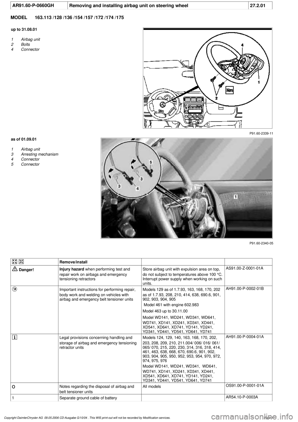
AR91.60-P-0660GH
Removing and installing airbag unit on steering wheel
27.2.01
MODEL
163.113 /128 /136 /154 /157 /172 /174 /175
P91.60-2339-11
up to 31.08.01
1
Airbag unit
2
Bolts
4
Connector
P91.60-2340-05
as of 01.09.01
1
Airbag unit
3
Arresting mechanism
4
Connector
5
Connector
Remove/install
Danger!
Injury hazard
when performing test and
repair work on airbags and emergency
tensioning retractorsStore airbag unit with expulsion area on top,
do not subject to temperatures above 100 °C.
Interrupt power supply when working on such
units.
AS91.00-Z-0001-01A
Important instructions for performing repair,
body work and welding on vehicles with
airbag and emergency belt tensioner units
Models 129 as of 1.7.93, 163, 168, 170, 202
as of 1.7.93, 208, 210, 414, 638, 690.6, 901,
902, 903, 904, 905
Model 461 with engine 602.983
Model 463 up to 30.11.00
Model WD141, WD241, WD341, WD641,
WD741, XD141, XD241, XD341, XD441,
XD541, XD641, XD741, YD141, YD241,
YD341, YD441, YD541, YD641, YD741
AH91.00-P-0002-01B
Legal provisions concerning handling and
storage of airbag and emergency tensioning
retractor units
Models 124, 129, 140, 163, 168, 170, 202,
203, 208, 209, 210, 211.004/ 006/ 016/ 061/
065/ 070, 215, 220, 230, 314, 316, 318, 414,
461, 463, 638, 668, 670, 690.6, 901, 902,
903, 904, 905, 950, 952, 953, 954, 970, 972,
974, 975, 976
Model WD141, WD241, WD341, WD641,
WD741, XD141, XD241, XD341, XD441,
XD541, XD641, XD741, YD141, YD241,
YD341, YD441, YD541, YD641, YD741
AH91.00-P-0004-01A
o
Notes regarding the disposal of airbag and
belt tensioner units
All models
OS91.00-P-0001-01A
1
Separate ground cable of battery
AR54.10-P-0003A
Copyright DaimlerChrysler AG 09.05.2006 CD-Ausgabe G/10/04 . This WIS print-out will not be recorde
d by Modification services.
Page 1
Page 3899 of 4133
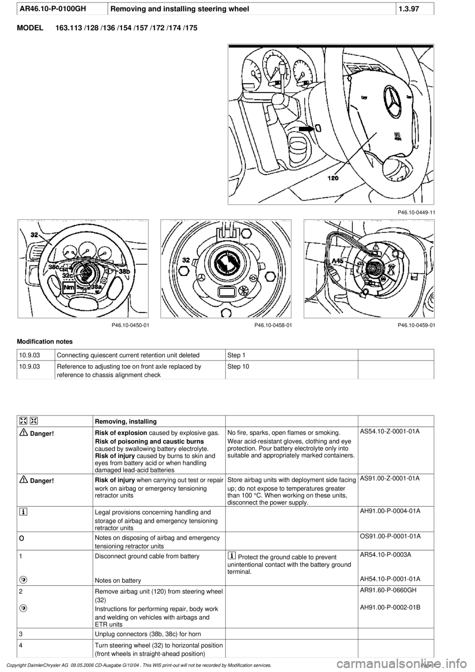
AR46.10-P-0100GHRemoving and installing steering wheel
1.3.97
MODEL
163.113 /128 /136 /154 /157 /172 /174 /175
P46.10-0449-11
P46.10-0450-01 P46.10-0458-01 P46.10-0459-01
Modification notes
10.9.03
Connecting quiescent current retention unit deleted
Step 1
10.9.03
Reference to adjusting toe on front axle replaced by
reference to chassis alignment check
Step 10
Removing, installing
Danger!
Risk of explosion
caused by explosive gas.
Risk of poisoning and caustic burns
caused by swallowing battery electrolyte.
Risk of injury
caused by burns to skin and
eyes from battery acid or when handling
damaged lead-acid batteries
No fire, sparks, open flames or smoking.
Wear acid-resistant gloves, clothing and eye
protection. Pour battery electrolyte only into
suitable and appropriately marked containers.
AS54.10-Z-0001-01A
Danger!
Risk of injury
when carrying out test or repair
work on airbag or emergency tensioning
retractor units
Store airbag units with deployment side facing
up; do not expose to temperatures greater
than 100 °C. When working on these units,
disconnect the power supply.
AS91.00-Z-0001-01A
Legal provisions concerning handling and
storage of airbag and emergency tensioning
retractor units
AH91.00-P-0004-01A
o
Notes on disposing of airbag and emergency
tensioning retractor units
OS91.00-P-0001-01A
1
Disconnect ground cable from battery
Protect the ground cable to prevent
unintentional contact with the battery ground
terminal.
AR54.10-P-0003A
Notes on battery
AH54.10-P-0001-01A
2
Remove airbag unit (120) from steering wheel
(32)
AR91.60-P-0660GH
Instructions for performing repair, body work
and welding on vehicles with airbags and
ETR units
AH91.00-P-0002-01B
3
Unplug connectors (38b, 38c) for horn
4
Turn steering wheel (32) to horizontal position
(front wheels in straight-ahead position)
Copyright DaimlerChrysler AG 09.05.2006 CD-Ausgabe G/10/04 . This WIS print-out will not be recorde
d by Modification services.
Page 1