1997 MERCEDES-BENZ ML350 door lock
[x] Cancel search: door lockPage 2075 of 4133
AR20.00-P-1142M
Drain, pour in coolant
8.11.99
ENGINE
612.963 in MODEL 163.113
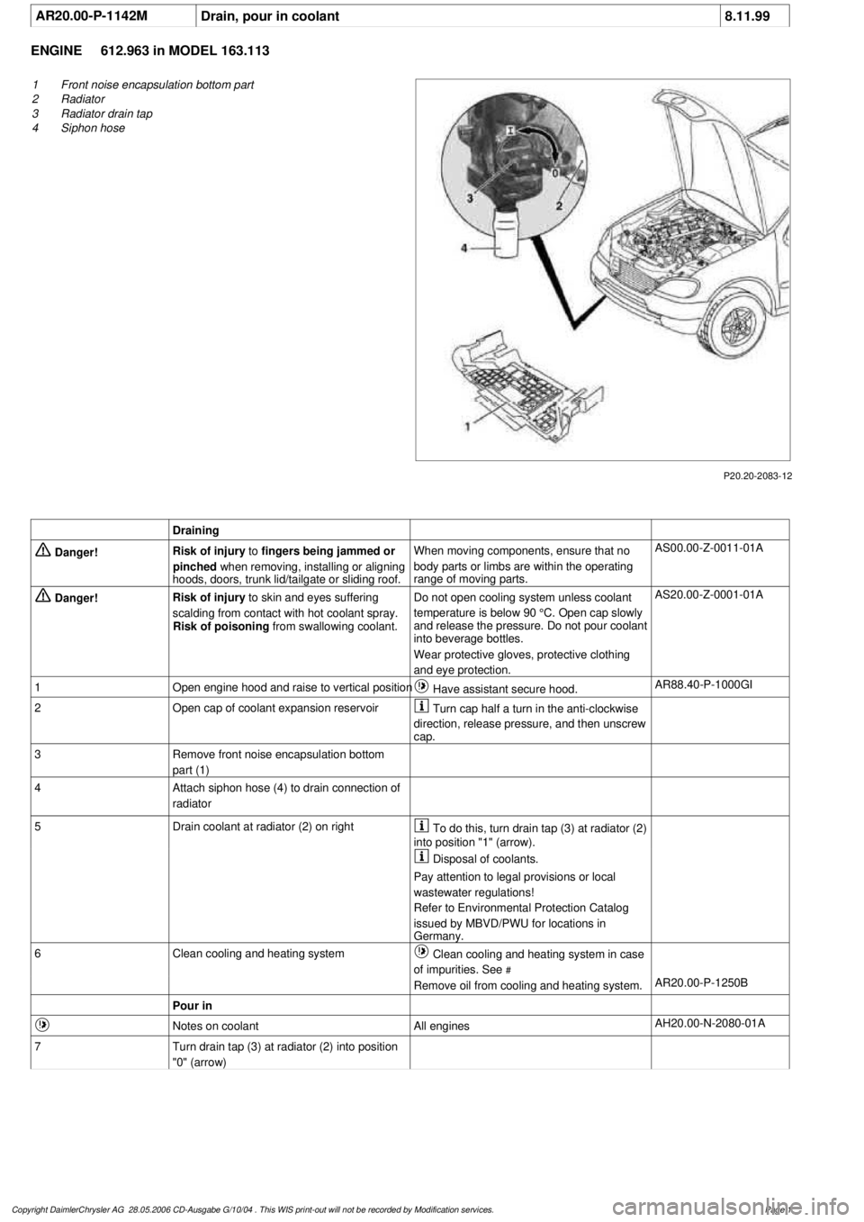
P20.20-2083-12
1
Front noise encapsulation bottom part
2
Radiator
3
Radiator drain tap
4
Siphon hose
Draining
Danger!
Risk of injury
to
fingers being jammed or
pinched
when removing, installing or aligning
hoods, doors, trunk lid/tailgate or sliding roof.
When moving components, ensure that no
body parts or limbs are within the operating
range of moving parts.
AS00.00-Z-0011-01A
Danger!
Risk of injury
to skin and eyes suffering
scalding from contact with hot coolant spray.
Risk of poisoning
from swallowing coolant.
Do not open cooling system unless coolant
temperature is below 90 °C. Open cap slowly
and release the pressure. Do not pour coolant
into beverage bottles.
Wear protective gloves, protective clothing
and eye protection.
AS20.00-Z-0001-01A
1
Open engine hood and raise to vertical position
Have assistant secure hood.
AR88.40-P-1000GI
2
Open cap of coolant expansion reservoir
Turn cap half a turn in the anti-clockwise
direction, release pressure, and then unscrew
cap.
3
Remove front noise encapsulation bottom
part (1)
4
Attach siphon hose (4) to drain connection of
radiator
5
Drain coolant at radiator (2) on right
To do this, turn drain tap (3) at radiator (2)
into position "1" (arrow).
Disposal of coolants.
Pay attention to legal provisions or local
wastewater regulations!
Refer to Environmental Protection Catalog
issued by MBVD/PWU for locations in
Germany.
6
Clean cooling and heating system
Clean cooling and heating system in case
of impurities. See
#
Remove oil from cooling and heating system.
AR20.00-P-1250B
Pour in
Notes on coolant
All engines
AH20.00-N-2080-01A
7
Turn drain tap (3) at radiator (2) into position
"0" (arrow)
Copyright DaimlerChrysler AG 28.05.2006 CD-Ausgabe G/10/04 . This WIS print-out will not be recorde
d by Modification services.
Page 1
Page 2112 of 4133
AR72.10-P-2400GH
Removing and installing outer door handle on front door
12.2.97
MODEL
163
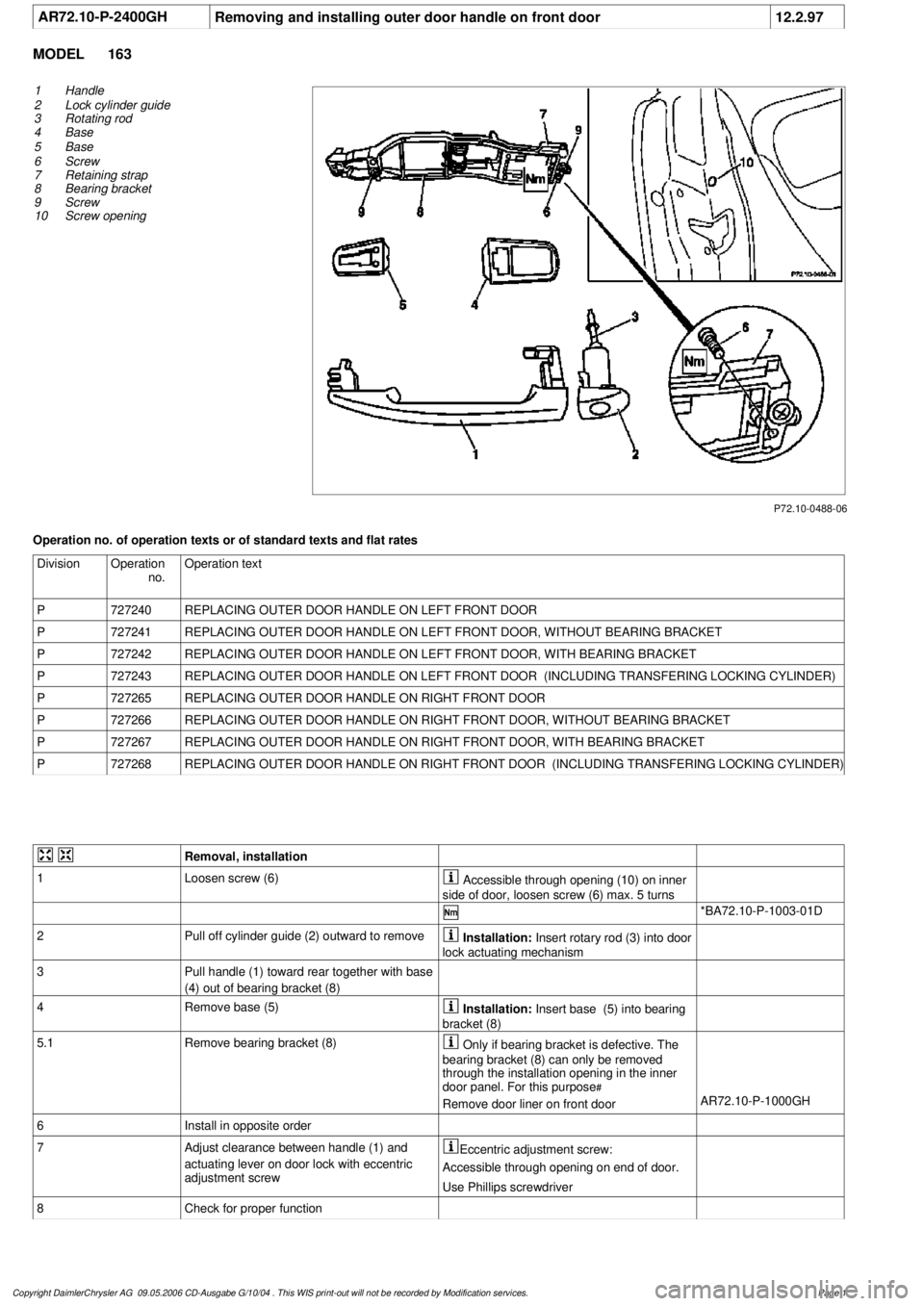
P72.10-0488-06
1
Handle
2
Lock cylinder guide
3
Rotating rod
4
Base
5
Base
6
Screw
7
Retaining strap
8
Bearing bracket
9
Screw
10
Screw opening
Operation no. of operation texts or of standard texts and flat rates
Division
Operation
no.
Operation text
P
727240
REPLACING OUTER DOOR HANDLE ON LEFT FRONT DOOR
P
727241
REPLACING OUTER DOOR HANDLE ON LEFT FRONT DOOR, WITHOUT BEARING BRACKET
P
727242
REPLACING OUTER DOOR HANDLE ON LEFT FRONT DOOR, WITH BEARING BRACKET
P
727243
REPLACING OUTER DOOR HANDLE ON LEFT FRONT DOOR (INCLUDING TRANSFERING LOCKING CYLINDER)
P
727265
REPLACING OUTER DOOR HANDLE ON RIGHT FRONT DOOR
P
727266
REPLACING OUTER DOOR HANDLE ON RIGHT FRONT DOOR, WITHOUT BEARING BRACKET
P
727267
REPLACING OUTER DOOR HANDLE ON RIGHT FRONT DOOR, WITH BEARING BRACKET
P
727268
REPLACING OUTER DOOR HANDLE ON RIGHT FRONT DOOR (INCLUDING TRANSFERING LOCKING CYLINDER)
Removal, installation
1
Loosen screw (6)
Accessible through opening (10) on inner
side of door, loosen screw (6) max. 5 turns
*BA72.10-P-1003-01D
2
Pull off cylinder guide (2) outward to remove
Installation:
Insert rotary rod (3) into door
lock actuating mechanism
3
Pull handle (1) toward rear together with base
(4) out of bearing bracket (8)
4
Remove base (5)
Installation:
Insert base (5) into bearing
bracket (8)
5.1
Remove bearing bracket (8)
Only if bearing bracket is defective. The
bearing bracket (8) can only be removed
through the installation opening in the inner
door panel. For this purpose
#
Remove door liner on front door
AR72.10-P-1000GH
6
Install in opposite order
7
Adjust clearance between handle (1) and
actuating lever on door lock with eccentric
adjustment screw
Eccentric adjustment screw:
Accessible through opening on end of door.
Use Phillips screwdriver
8
Check for proper function
Copyright DaimlerChrysler AG 09.05.2006 CD-Ausgabe G/10/04 . This WIS print-out will not be recorde
d by Modification services.
Page 1
Page 2115 of 4133
AF72.10-P-6003-01A
Adjusting front door lock
Front door
Number
Designation
Model 163
BA72.10-P-1004-01D
Screw on door lock
Nm
8
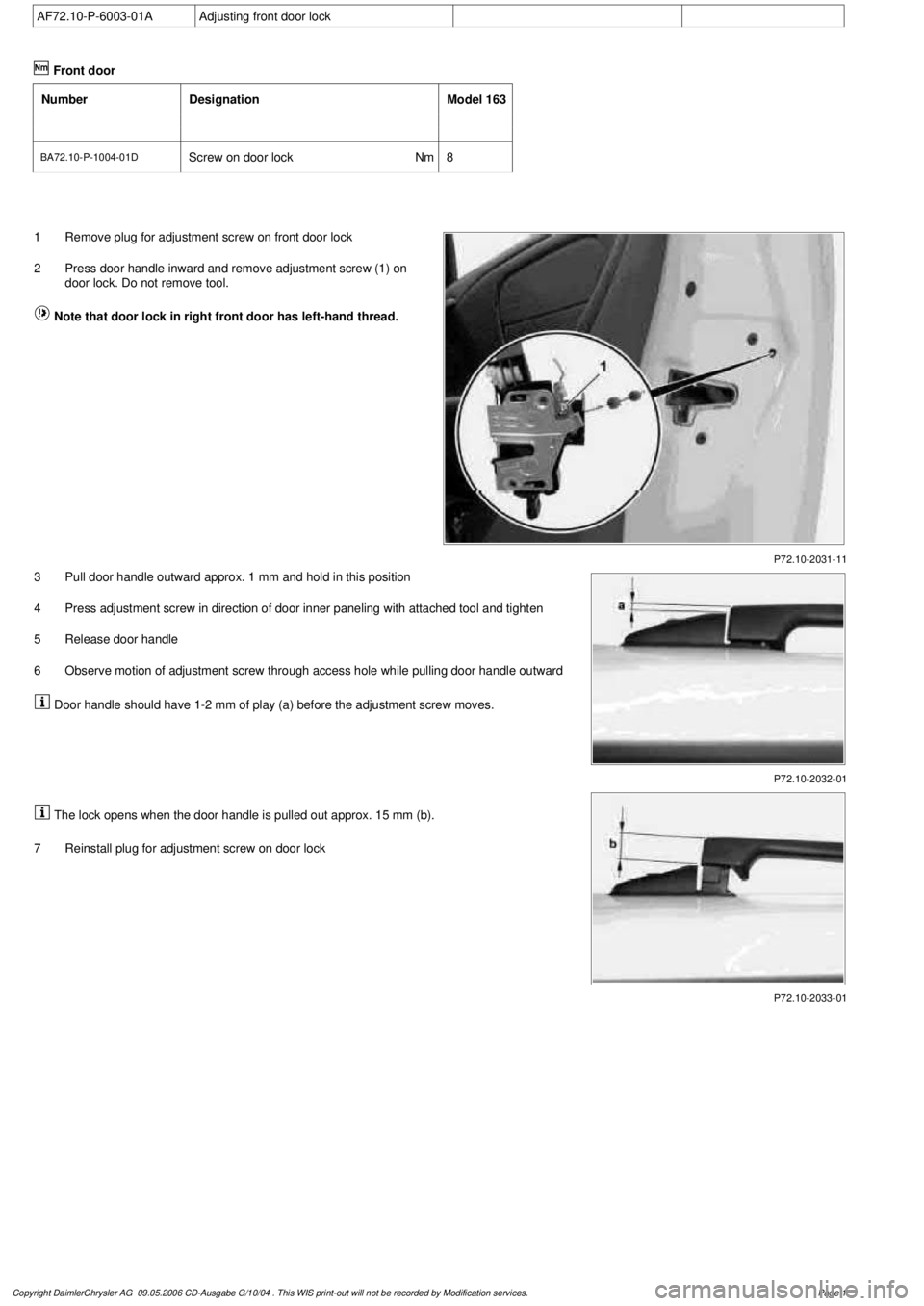
P72.10-2031-11
1
Remove plug for adjustment screw on front door lock
2
Press door handle inward and remove adjustment screw (1) on
door lock. Do not remove tool.
Note that door lock in right front door has left-hand thread.
P72.10-2032-01
3
Pull door handle outward approx. 1 mm and hold in this position
4
Press adjustment screw in direction of door inner paneling with attached tool and tighten
5
Release door handle
6
Observe motion of adjustment screw through access hole while pulling door handle outward
Door handle should have 1-2 mm of play (a) before the adjustment screw moves.
P72.10-2033-01
The lock opens when the door handle is pulled out approx. 15 mm (b).
7
Reinstall plug for adjustment screw on door lock
Copyright DaimlerChrysler AG 09.05.2006 CD-Ausgabe G/10/04 . This WIS print-out will not be recorde
d by Modification services.
Page 1
Page 2116 of 4133
AR72.10-P-4011GH
Removing and installing front door lock
13.2.97
MODEL
163
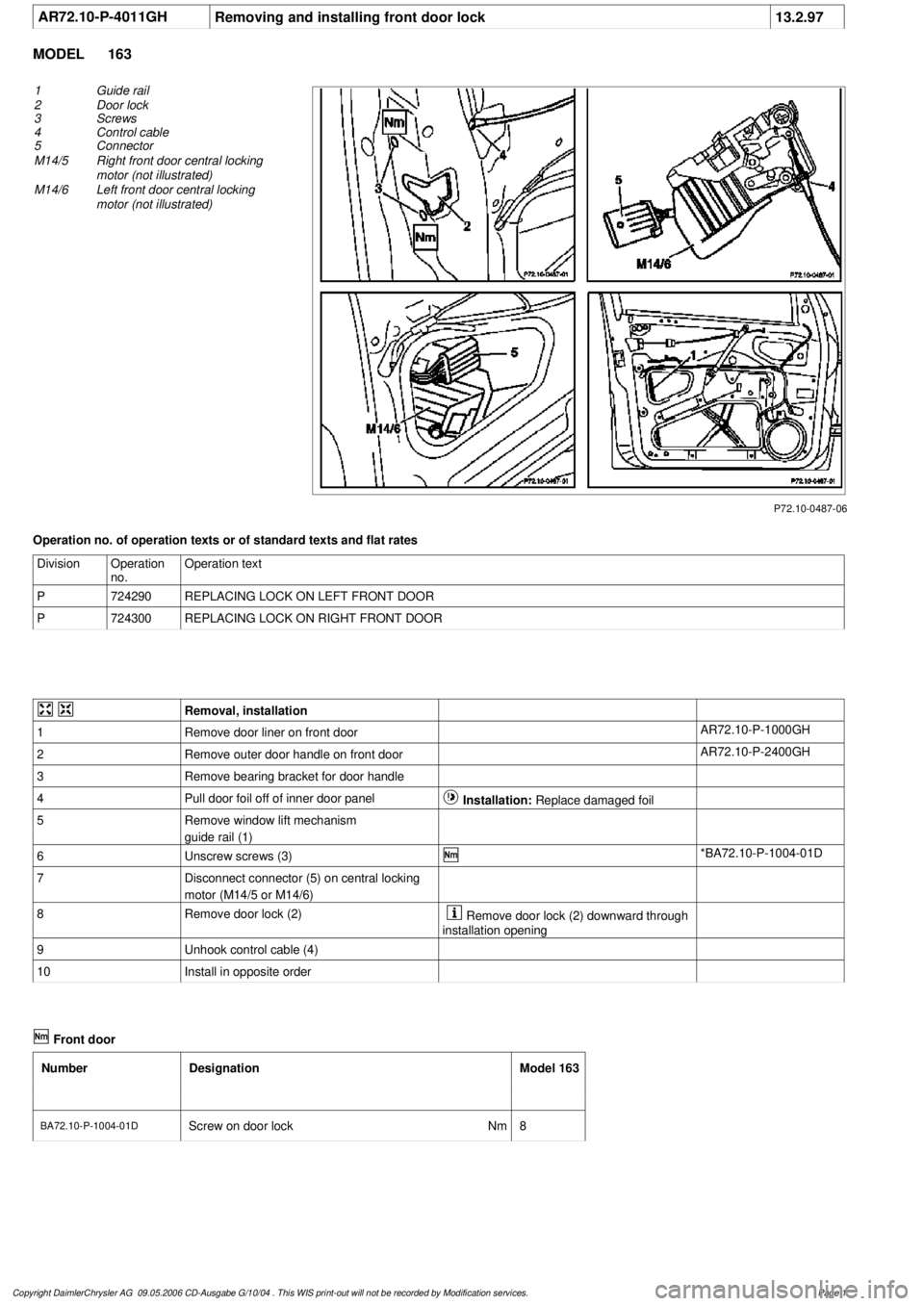
P72.10-0487-06
1
Guide rail
2
Door lock
3
Screws
4
Control cable
5
Connector
M14/5
Right front door central locking
motor (not illustrated)
M14/6
Left front door central locking
motor (not illustrated)
Operation no. of operation texts or of standard texts and flat rates
Division
Operation
no.
Operation text
P
724290
REPLACING LOCK ON LEFT FRONT DOOR
P
724300
REPLACING LOCK ON RIGHT FRONT DOOR
Removal, installation
1
Remove door liner on front door
AR72.10-P-1000GH
2
Remove outer door handle on front door
AR72.10-P-2400GH
3
Remove bearing bracket for door handle
4
Pull door foil off of inner door panel
Installation:
Replace damaged foil
5
Remove window lift mechanism
guide rail (1)
6
Unscrew screws (3)
*BA72.10-P-1004-01D
7
Disconnect connector (5) on central locking
motor (M14/5 or M14/6)
8
Remove door lock (2)
Remove door lock (2) downward through
installation opening
9
Unhook control cable (4)
10
Install in opposite order
Front door
Number
Designation
Model 163
BA72.10-P-1004-01D
Screw on door lock
Nm
8
Copyright DaimlerChrysler AG 09.05.2006 CD-Ausgabe G/10/04 . This WIS print-out will not be recorde
d by Modification services.
Page 1
Page 2117 of 4133

SI72.10-P-0001A
Service Information on adjusting front door lock
19.6.98
MODEL
163
Repairs concerning complaints about the front door not being
able to be opened after unlocking the vehicle, should be addressed in
the following manner:
1.
Adjust the door lock
2.
If attempt to adjust door lock was unsuccessful, replace door
lock.
The majority of door locks being returned under warranty for this
complaint have been found to be servicable after adjustment.
1
Adjust front door lock
If adjustment unsuccessful
#
AF72.10-P-6003-01A
Replace front door lock
AR72.10-P-4011GH
Copyright DaimlerChrysler AG 09.05.2006 CD-Ausgabe G/10/04 . This WIS print-out will not be recorde
d by Modification services.
Page 1
Page 2124 of 4133
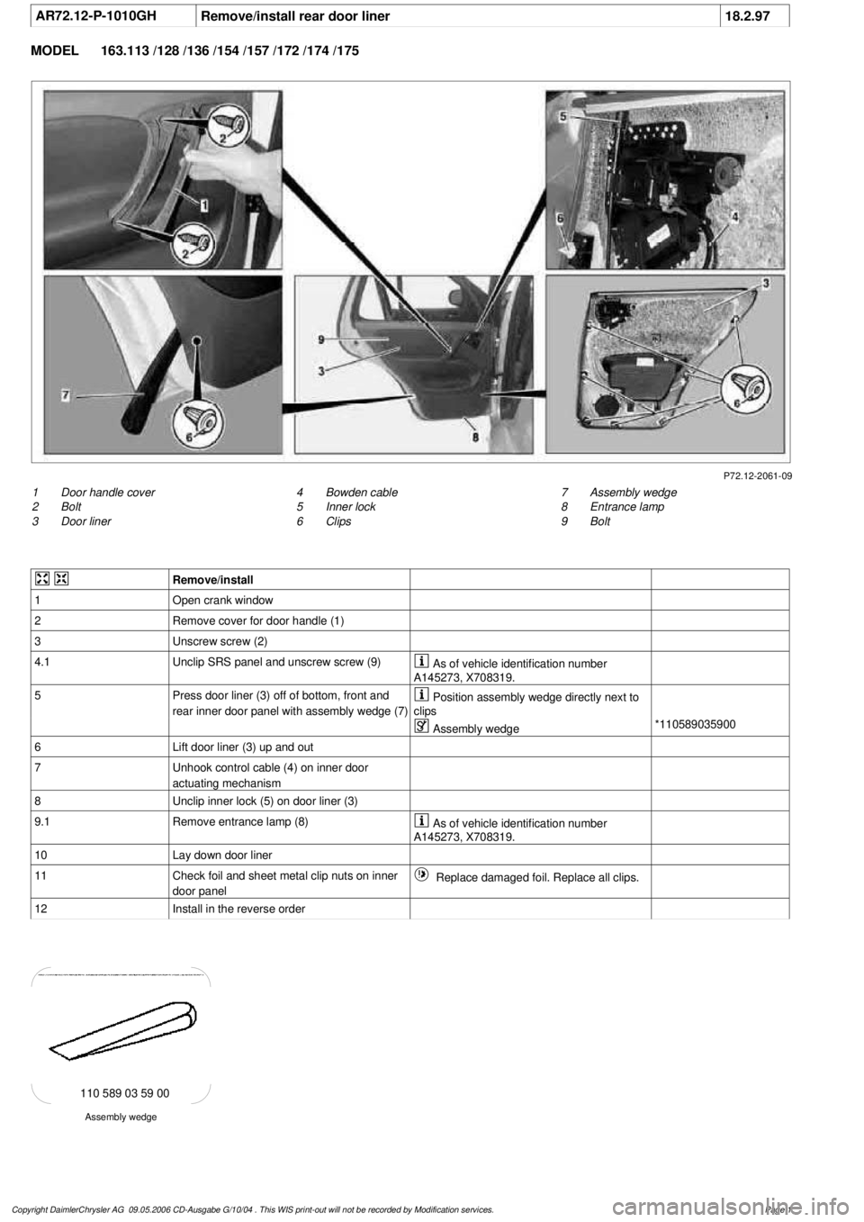
AR72.12-P-1010GH
Remove/install rear door liner
18.2.97
MODEL
163.113 /128 /136 /154 /157 /172 /174 /175
P72.12-2061-09
1
Door handle cover
2
Bolt
3
Door liner
7
Assembly wedge
8
Entrance lamp
9
Bolt
4
Bowden cable
5
Inner lock
6
Clips
Remove/install
1
Open crank window
2
Remove cover for door handle (1)
3
Unscrew screw (2)
4.1
Unclip SRS panel and unscrew screw (9)
As of vehicle identification number
A145273, X708319.
5
Press door liner (3) off of bottom, front and
rear inner door panel with assembly wedge (7)
Position assembly wedge directly next to
clips
Assembly wedge
*110589035900
6
Lift door liner (3) up and out
7
Unhook control cable (4) on inner door
actuating mechanism
8
Unclip inner lock (5) on door liner (3)
9.1
Remove entrance lamp (8)
As of vehicle identification number
A145273, X708319.
10
Lay down door liner
11
Check foil and sheet metal clip nuts on inner
door panel
Replace damaged foil. Replace all clips.
12
Install in the reverse order
Assembly wedge
110 589 03 59 00
Copyright DaimlerChrysler AG 09.05.2006 CD-Ausgabe G/10/04 . This WIS print-out will not be recorde
d by Modification services.
Page 1
Page 2141 of 4133
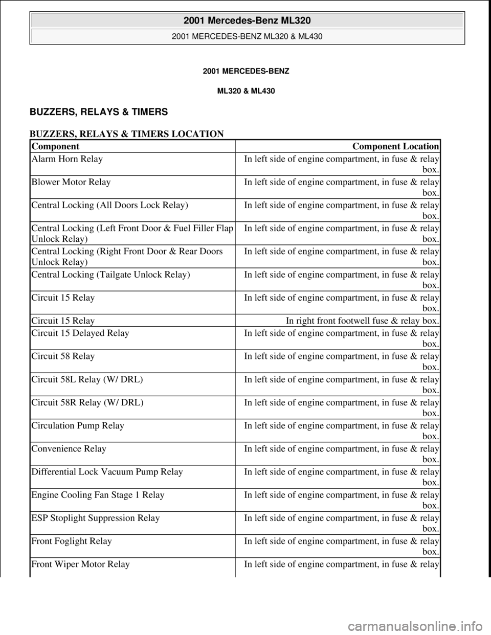
2001 MERCEDES-BENZ
ML320 & ML430
BUZZERS, RELAYS & TIMERS
BUZZERS, RELAYS & TIMERS LOCATION
ComponentComponent Location
Alarm Horn RelayIn left side of engine compartment, in fuse & relay
box.
Blower Motor RelayIn left side of engine compartment, in fuse & relay
box.
Central Locking (All Doors Lock Relay)In left side of engine compartment, in fuse & relay
box.
Central Locking (Left Front Door & Fuel Filler Flap
Unlock Relay)In left side of engine compartment, in fuse & relay
box.
Central Locking (Right Front Door & Rear Doors
Unlock Relay)In left side of engine compartment, in fuse & relay
box.
Central Locking (Tailgate Unlock Relay)In left side of engine compartment, in fuse & relay
box.
Circuit 15 RelayIn left side of engine compartment, in fuse & relay
box.
Circuit 15 RelayIn right front footwell fuse & relay box.
Circuit 15 Delayed RelayIn left side of engine compartment, in fuse & relay
box.
Circuit 58 RelayIn left side of engine compartment, in fuse & relay
box.
Circuit 58L Relay (W/ DRL)In left side of engine compartment, in fuse & relay
box.
Circuit 58R Relay (W/ DRL)In left side of engine compartment, in fuse & relay
box.
Circulation Pump RelayIn left side of engine compartment, in fuse & relay
box.
Convenience RelayIn left side of engine compartment, in fuse & relay
box.
Differential Lock Vacuum Pump RelayIn left side of engine compartment, in fuse & relay
box.
Engine Cooling Fan Stage 1 RelayIn left side of engine compartment, in fuse & relay
box.
ESP Stoplight Suppression RelayIn left side of engine compartment, in fuse & relay
box.
Front Foglight RelayIn left side of engine compartment, in fuse & relay
box.
Front Wiper Motor RelayIn left side of engine compartment, in fuse & relay
2001 Mercedes-Benz ML320
2001 MERCEDES-BENZ ML320 & ML430
2001 Mercedes-Benz ML320
2001 MERCEDES-BENZ ML320 & ML430
me
Saturday, October 02, 2010 3:21:17 PMPage 1 © 2006 Mitchell Repair Information Company, LLC.
me
Saturday, October 02, 2010 3:21:20 PMPage 1 © 2006 Mitchell Repair Information Company, LLC.
Page 2516 of 4133
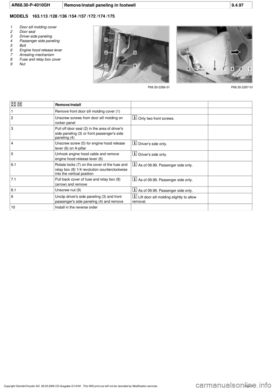
AR68.30-P-4010GHRemove/install paneling in footwell
9.4.97
MODELS
163.113 /128 /136 /154 /157 /172 /174 /175
P68.30-2266-01
1
Door sill molding cover
2
Door seal
3
Driver-side paneling
4
Passenger side paneling
5
Bolt
6
Engine hood release lever
7
Arresting mechanism
8
Fuse and relay box cover
9
Nut
P68.30-2267-01
Remove/install
1
Remove front door sill molding cover (1)
2
Unscrew screws from door sill molding on
rocker panel
Only two front screws.
3
Pull off door seal (2) in the area of driver's
side paneling (3) or front passenger's side
paneling (4)
4
Unscrew screw (5) for engine hood release
lever (6) on A-pillar
Driver's side only.
5
Unhook engine hood cable and remove
engine hood release lever (6)
Driver's side only.
6.1
Rotate locks (7) on the cover of the fuse and
relay box (8) 1/4 revolution counterclockwise
into the vertical position
As of 09.99. Passenger side only.
7.1
Pull back cover of fuse and relay box (8)
(arrow) and remove
As of 09.99. Passenger side only.
8.1
Unscrew nut (9)
As of 09.99. Passenger side only.
9
Unclip driver's side paneling (3) and front
passenger's side paneling (4) and remove
Lift door sill molding slightly to allow
removal.
10
Install in the reverse order
Copyright DaimlerChrysler AG 09.05.2006 CD-Ausgabe G/10/04 . This WIS print-out will not be recorde
d by Modification services.
Page 1