1997 MERCEDES-BENZ ML350 door lock
[x] Cancel search: door lockPage 1839 of 4133
Only if fuse is not already present.
14 Insert enclosed 15 A fu se into plug position F40.
15 Fix wiring harness of illuminated door sill molding in fuse and relay module (F1).
16 Attach fuse block.
2 bolts.
17 Insert foam rubber block into rear of fuse and relay module.
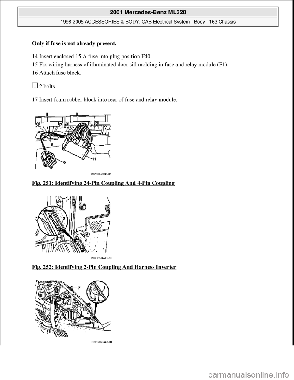
Fig. 251: Identifying 24
-Pin Coupling And 4-Pin Coupling
Fig. 252: Identifying 2
-Pin Coupling And Harness Inverter
2001 Mercedes-Benz ML320
1998-2005 ACCESSORIES & BODY, CAB Electr ical System - Body - 163 Chassis
me
Saturday, October 02, 2010 3:30:11 PMPage 344 © 2006 Mitchell Repair Information Company, LLC.
Page 1841 of 4133
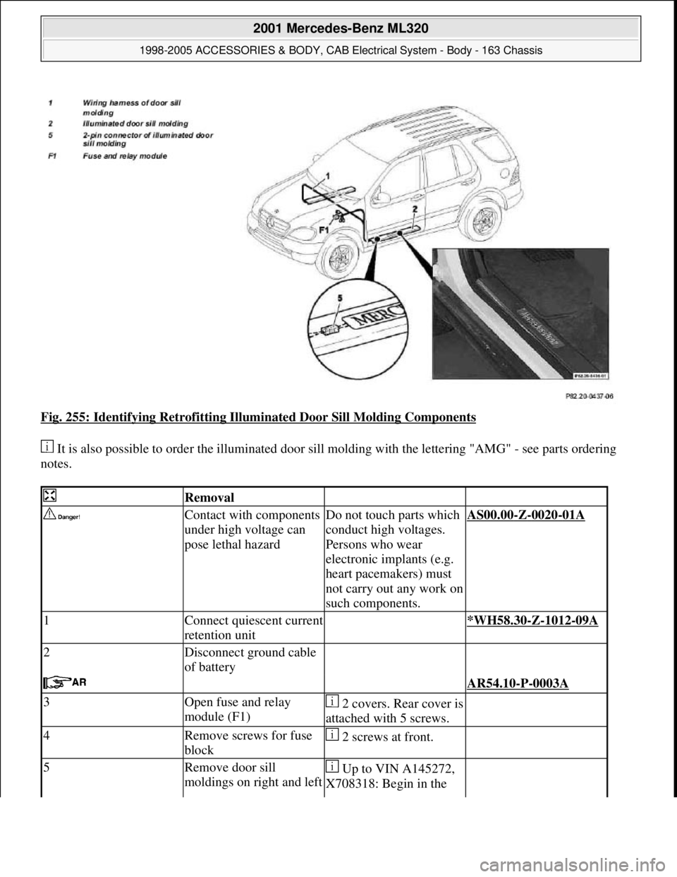
Fig. 255: Identifying Retrofitting Illuminated Door Sill Molding Components
It is also possible to order the illuminated door sill molding with the lettering "AMG" - see parts ordering
notes.
Removal
Contact with components
under high voltage can
pose lethal hazardDo not touch parts which
conduct high voltages.
Persons who wear
electronic implants (e.g.
heart pacemakers) must
not carry out any work on
such components.AS00.00-Z-0020-01A
1Connect quiescent current
retention unit *WH58.30-Z-1012-09A
2Disconnect ground cable
of battery
AR54.10-P-0003A
3Open fuse and relay
module (F1)2 covers. Rear cover is
attached with 5 screws.
4Remove screws for fuse
block 2 screws at front.
5Remove door sill
moldings on right and left Up to VIN A145272,
X708318: Begin in the
2001 Mercedes-Benz ML320
1998-2005 ACCESSORIES & BODY, CAB Electrical System - Body - 163 Chassis
me
Saturday, October 02, 2010 3:30:11 PMPage 346 © 2006 Mitchell Repair Information Company, LLC.
Page 2028 of 4133
GF80.20-P-0005-01GH
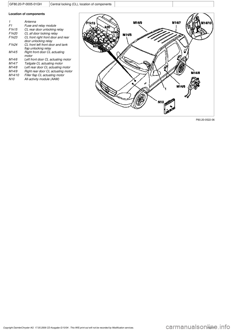
Central locking (CL), location of components
P80.20-0522-06
Location of components
1
Antenna
F1
Fuse and relay module
F1k15
CL rear door unlocking relay
F1k20
CL all door locking relay
F1k23
CL front right front door and rear
door unlocking relay
F1k24
CL front left front door and tank
flap unlocking relay
M14/5
Right front door CL actuating
motor
M14/6
Left front door CL actuating motor
M14/7
Tailgate CL actuating motor
M14/8
Left rear door CL actuating motor
M14/9
Right rear door CL actuating motor
M14/10
Filler flap CL actuating motor
N10
All-activity module (AAM)
Copyright DaimlerChrysler AG 17.05.2006 CD-Ausgabe G/10/04 . This WIS print-out will not be recorde
d by Modification services.
Page 1
Page 2029 of 4133

AD80.20-P-6001-43GH
CL test of electrical system motor actuation
relay
t
A
Scope of test
Measuring instrument/
Test connection
Operation/Requirement
Specified value
D
Possible cause/Remedy
1.0
Central locking locks
everything
HHT actuation
A
All doors closed and
unlocked.
All doors and
fuel tank flap
are locked
D
Individual doors are not
locked:
t
1.1
D
No door is locked:
t
1.2
1.1
Central locking unlocks
everything
HHT actuation
A
All doors closed and locked.
All doors and
fuel tank flap
are unlocked
D
Left front door and fuel
tank flap are not unlocked:
t
1.3
D
Right front door and rear
doors are not unlocked:
t
1.4
D
Tailgate is not unlocked:
t
1.5
D
No door is unlocked:
Cables, N10
1.2
Central locking relay,
lock all doors (F1k20)
Function
Replace relay (F1k20) by
relay (F1k15),
Repeat test
t
1.0
All doors and
fuel tank flap
are locked
If test 1.0 in order:
D
Relay (F1k20)
otherwise:
D
Cables
1.3
Central locking relay,
unlock left door and fuel
tank flap (F1k24)
Function
Replace relay (F1k24) by
relay (F1k15), close and
lock left front door
A
Actuation of unlocking
left front door.
Left front door
is unlocked
Value in order:
D
Relay (F1k24)
Value not in order:
D
Cables
1.4
Central locking relay,
unlock right door and
rear doors (F1k23)
Function
Replace relay (F1k23) by
(F1k15), repeat test
t
1.1
All doors and
fuel tank flap
are unlocked
If the same fault pattern
emerges when test 1.1 is
repeated:
D
Cables
D
All-Activity Module (AAM)
(N10)
Tailgate is not unlocked:
D
Relay (F1k23)
1.5
Central locking relay,
unlock tailgate (F1k15)
Function
Replace relay (F1k15) by
(F1k23), close and lock
tailgate
A
Actuation of unlocking
tailgate
Tailgate is
unlocked
Value in order:
D
Relay (F1k15)
Value not in order:
D
Cables
Copyright DaimlerChrysler AG 17.05.2006 CD-Ausgabe G/10/04 . This WIS print-out will not be recorde
d by Modification services.
Page 1
Page 2030 of 4133
AR09.41-P-6817MM
Removing and installing charge air cooler
10.11.99
ENGINE
612.963 in MODEL 163.113
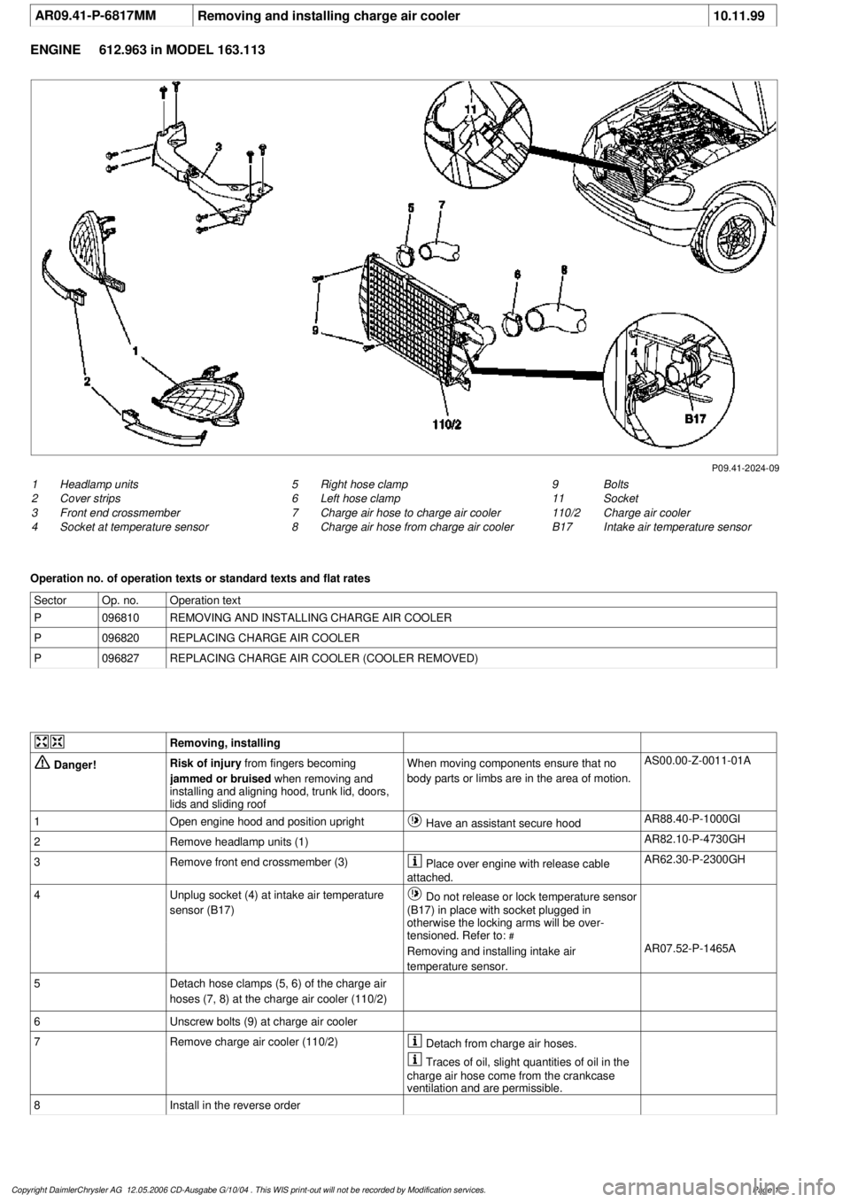
P09.41-2024-09
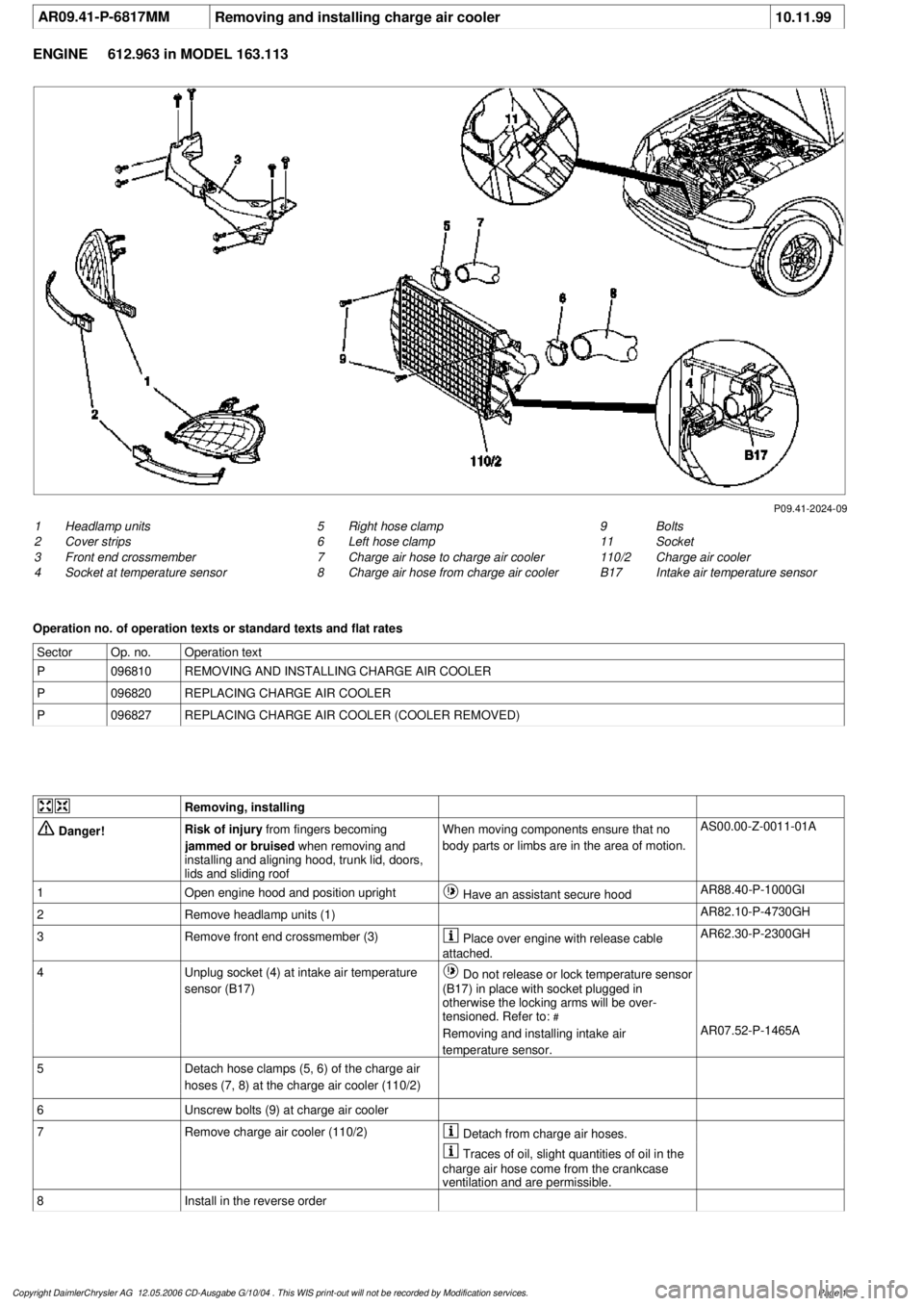
1
Headlamp units
2
Cover strips
3
Front end crossmember
4
Socket at temperature sensor
9
Bolts
11
Socket
110/2
Charge air cooler
B17
Intake air temperature sensor
5
Right hose clamp
6
Left hose clamp
7
Charge air hose to charge air cooler
8
Charge air hose from charge air cooler
Operation no. of operation texts or standard texts and flat rates
Sector
Op. no.
Operation text
P
096810
REMOVING AND INSTALLING CHARGE AIR COOLER
P
096820
REPLACING CHARGE AIR COOLER
P
096827
REPLACING CHARGE AIR COOLER (COOLER REMOVED)
Removing, installing
Danger!
Risk of injury
from fingers becoming
jammed or bruised
when removing and
installing and aligning hood, trunk lid, doors,
lids and sliding roof
When moving components ensure that no
body parts or limbs are in the area of motion.
AS00.00-Z-0011-01A
1
Open engine hood and position upright
Have an assistant secure hood
AR88.40-P-1000GI
2
Remove headlamp units (1)
AR82.10-P-4730GH
3
Remove front end crossmember (3)
Place over engine with release cable
attached.
AR62.30-P-2300GH
4
Unplug socket (4) at intake air temperature
sensor (B17)
Do not release or lock temperature sensor
(B17) in place with socket plugged in
otherwise the locking arms will be over-
tensioned. Refer to:
#
Removing and installing intake air
temperature sensor.
AR07.52-P-1465A
5
Detach hose clamps (5, 6) of the charge air
hoses (7, 8) at the charge air cooler (110/2)
6
Unscrew bolts (9) at charge air cooler
7
Remove charge air cooler (110/2)
Detach from charge air hoses.
Traces of oil, slight quantities of oil in the
charge air hose come from the crankcase
ventilation and are permissible.
8
Install in the reverse order
Copyright DaimlerChrysler AG 12.05.2006 CD-Ausgabe G/10/04 . This WIS print-out will not be recorde
d by Modification services.
Page 1
Page 2032 of 4133
AR09.41-P-6817MM
Removing and installing charge air cooler
10.11.99
ENGINE
612.963 in MODEL 163.113
P09.41-2024-09
1
Headlamp units
2
Cover strips
3
Front end crossmember
4
Socket at temperature sensor
9
Bolts
11
Socket
110/2
Charge air cooler
B17
Intake air temperature sensor
5
Right hose clamp
6
Left hose clamp
7
Charge air hose to charge air cooler
8
Charge air hose from charge air cooler
Operation no. of operation texts or standard texts and flat rates
Sector
Op. no.
Operation text
P
096810
REMOVING AND INSTALLING CHARGE AIR COOLER
P
096820
REPLACING CHARGE AIR COOLER
P
096827
REPLACING CHARGE AIR COOLER (COOLER REMOVED)
Removing, installing
Danger!
Risk of injury
from fingers becoming
jammed or bruised
when removing and
installing and aligning hood, trunk lid, doors,
lids and sliding roof
When moving components ensure that no
body parts or limbs are in the area of motion.
AS00.00-Z-0011-01A
1
Open engine hood and position upright
Have an assistant secure hood
AR88.40-P-1000GI
2
Remove headlamp units (1)
AR82.10-P-4730GH
3
Remove front end crossmember (3)
Place over engine with release cable
attached.
AR62.30-P-2300GH
4
Unplug socket (4) at intake air temperature
sensor (B17)
Do not release or lock temperature sensor
(B17) in place with socket plugged in
otherwise the locking arms will be over-
tensioned. Refer to:
#
Removing and installing intake air
temperature sensor.
AR07.52-P-1465A
5
Detach hose clamps (5, 6) of the charge air
hoses (7, 8) at the charge air cooler (110/2)
6
Unscrew bolts (9) at charge air cooler
7
Remove charge air cooler (110/2)
Detach from charge air hoses.
Traces of oil, slight quantities of oil in the
charge air hose come from the crankcase
ventilation and are permissible.
8
Install in the reverse order
Copyright DaimlerChrysler AG 12.05.2006 CD-Ausgabe G/10/04 . This WIS print-out will not be recorde
d by Modification services.
Page 1
Page 2067 of 4133

GF72.29-P-2002GH
Convenience control, function
7.4.97
MODEL
163
The convenience control allows the driver to operate the electrical
seat adjustment, the power windows, the electric vent windows, the
electric outside rearview mirror as well as the electric sliding/pop-up
roof or the electric lamella sliding roof
when the ignition is switched
off.
To achieve this, the all-activity module (AAM) (N10) switches to the
corresponding loads via the convenience relay (F1k14)
circuit 30 .
As of 12.99 the vehicle is equipped with its own convenience relay for
seat adjustment (relay 1, F2k1). In addition the status of the
convenience control via CAN is transmitted to the extended activity
module (EAM, N10/1).
Conditions for control actuation
On all-activity module (AAM) (N10) configured for
I
up
to
11.99:
The convenience actuation becomes active as soon as
D
Circuit 15 ON is recognized
When circuit 15 is switched off, the convenience actuation is
deactivated after a door is opened
Otherwise
The convenience actuation is active in the following cases:
D
Circuit 15c ON
D
A front door is open
D
The remote control key is removed, however, the doors are not
yet opened
In both cases the convenience actuation remains active for 5 min.
Switch-on condition for circuit 15c
When the remote control key is inserted into the ignition lock, circuit
15c is switched on when the key is turned out of the zero position.
Circuit 15c switches off only after the remote control key is removed
from the ignition lock
Electric seat adjustment without memory,
function
GF91.29-P-0003GH
Electric seat adjustment with memory, function
as of 12.99
GF91.29-P-0002GH
Convenience control, function
for electrical seat adjustment as of 12.99
GF91.29-P-2013GK
Power windows, function
GF72.29-P-0003GH
Power tilting/sliding roof (SR), function
GF77.20-P-0001GH
Electrically adjustable outside rearview
mirrors, function
GF88.79-P-0005GH
Electric vent windows, function
GF67.39-P-1000GH
Extended activity module,
location/purpose/design
as of 12.99
GF54.21-P-4107GK
Copyright DaimlerChrysler AG 04.08.2006 CD-Ausgabe G/10/04 . This WIS print-out will not be recorde
d by Modification services.
Page 1
Page 2068 of 4133
AR20.00-P-1142M
Drain, pour in coolant
8.11.99
ENGINE
612.963 in MODEL 163.113
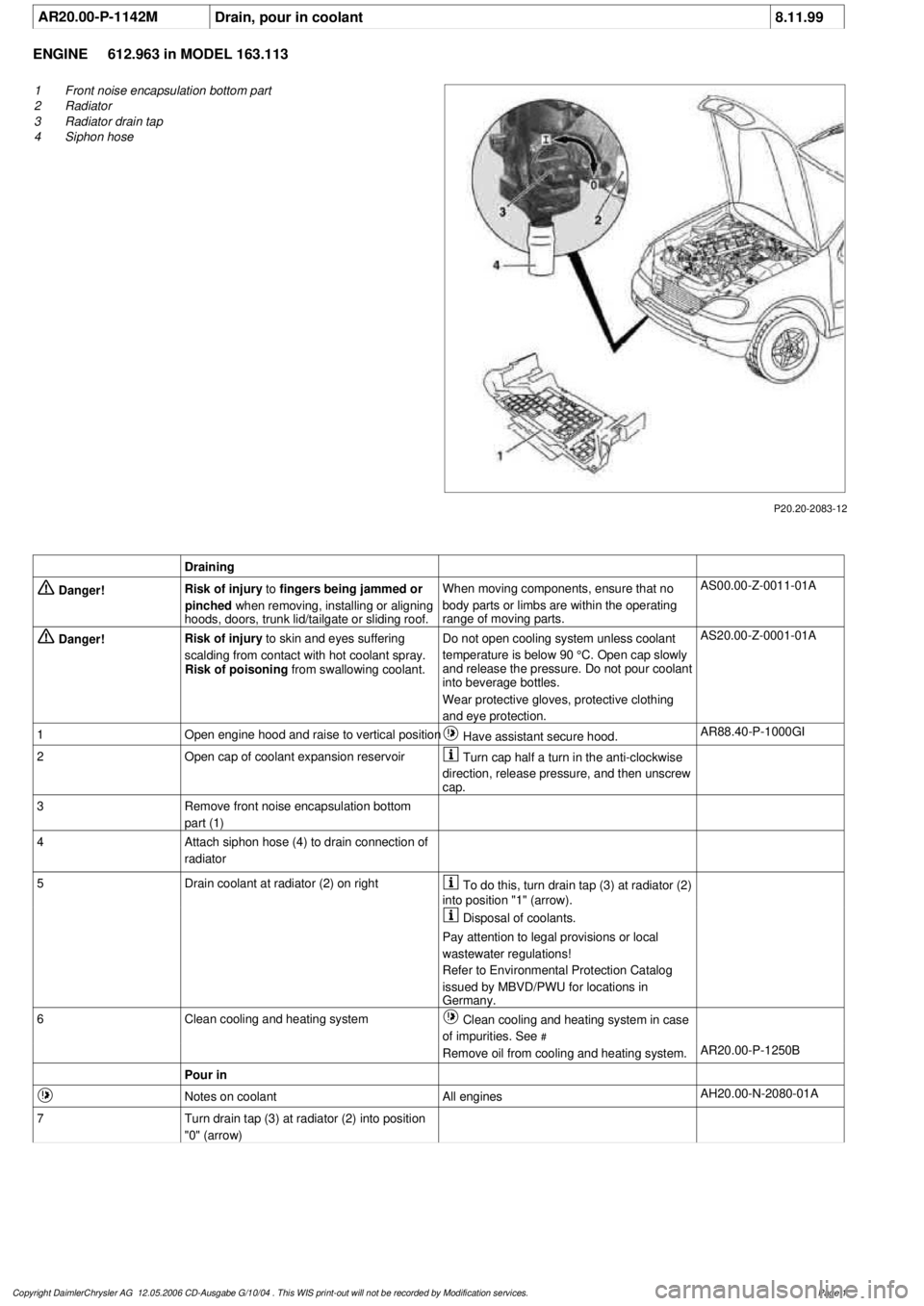
P20.20-2083-12
1
Front noise encapsulation bottom part
2
Radiator
3
Radiator drain tap
4
Siphon hose
Draining
Danger!
Risk of injury
to
fingers being jammed or
pinched
when removing, installing or aligning
hoods, doors, trunk lid/tailgate or sliding roof.
When moving components, ensure that no
body parts or limbs are within the operating
range of moving parts.
AS00.00-Z-0011-01A
Danger!
Risk of injury
to skin and eyes suffering
scalding from contact with hot coolant spray.
Risk of poisoning
from swallowing coolant.
Do not open cooling system unless coolant
temperature is below 90 °C. Open cap slowly
and release the pressure. Do not pour coolant
into beverage bottles.
Wear protective gloves, protective clothing
and eye protection.
AS20.00-Z-0001-01A
1
Open engine hood and raise to vertical position
Have assistant secure hood.
AR88.40-P-1000GI
2
Open cap of coolant expansion reservoir
Turn cap half a turn in the anti-clockwise
direction, release pressure, and then unscrew
cap.
3
Remove front noise encapsulation bottom
part (1)
4
Attach siphon hose (4) to drain connection of
radiator
5
Drain coolant at radiator (2) on right
To do this, turn drain tap (3) at radiator (2)
into position "1" (arrow).
Disposal of coolants.
Pay attention to legal provisions or local
wastewater regulations!
Refer to Environmental Protection Catalog
issued by MBVD/PWU for locations in
Germany.
6
Clean cooling and heating system
Clean cooling and heating system in case
of impurities. See
#
Remove oil from cooling and heating system.
AR20.00-P-1250B
Pour in
Notes on coolant
All engines
AH20.00-N-2080-01A
7
Turn drain tap (3) at radiator (2) into position
"0" (arrow)
Copyright DaimlerChrysler AG 12.05.2006 CD-Ausgabe G/10/04 . This WIS print-out will not be recorde
d by Modification services.
Page 1