1997 MERCEDES-BENZ ML350 door lock
[x] Cancel search: door lockPage 1528 of 4133
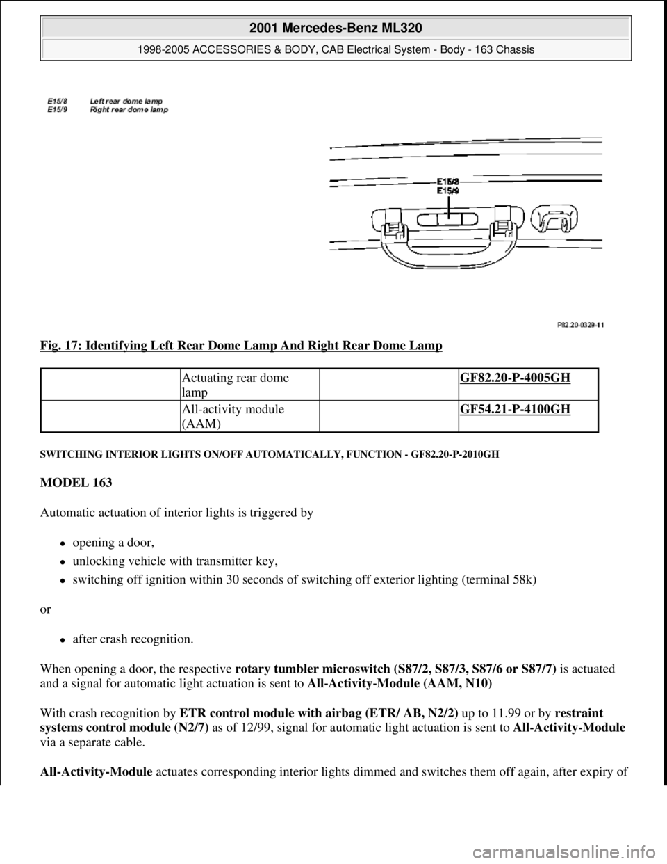
Fig. 17: Identifying Left Rear Dome Lamp And Right Rear Dome Lamp
SWITCHING INTERIOR LIGHTS ON/OFF AUTOMATICALLY, FUNCTION - GF82.20-P-2010GH
MODEL 163
Automatic actuation of interior lights is triggered by
opening a door,
unlocking vehicle with transmitter key,
switching off ignition within 30 seconds of switching off exterior lighting (terminal 58k)
or
after crash recognition.
When opening a door, the respective rotary tumbler microswitch (S87/2, S87/3, S87/6 or S87/7) is actuated
and a signal for automatic light actuation is sent to All-Activity-Module (AAM, N10)
With crash recognition by ETR control module with airbag (ETR/ AB, N2/2) up to 11.99 or by restraint
systems control module (N2/7) as of 12/99, signal for automatic light actuation is sent to All-Activity-Module
via a separate cable.
All-Activity-Module actuates correspondin
g interior lights dimmed and switches them off again, after expiry of
Actuating rear dome
lamp GF82.20-P-4005GH
All-activity module
(AAM) GF54.21-P-4100GH
2001 Mercedes-Benz ML320
1998-2005 ACCESSORIES & BODY, CAB Electrical System - Body - 163 Chassis
me
Saturday, October 02, 2010 3:30:04 PMPage 33 © 2006 Mitchell Repair Information Company, LLC.
Page 1529 of 4133
switched-on time.
Lights switched on manually cannot be switched off by All-Activity-Module.
Rear interior lamp (E15/3) is actuated directly by opening of rear door and not via All-Activity-Module.
Front and rear entrance and exit lamps (E17/3, E17/4, E17/5 and E17/6) introduced as of 12/99 are
actuated via the Extended-Activity-Module (EAM) when corresponding door is opened.
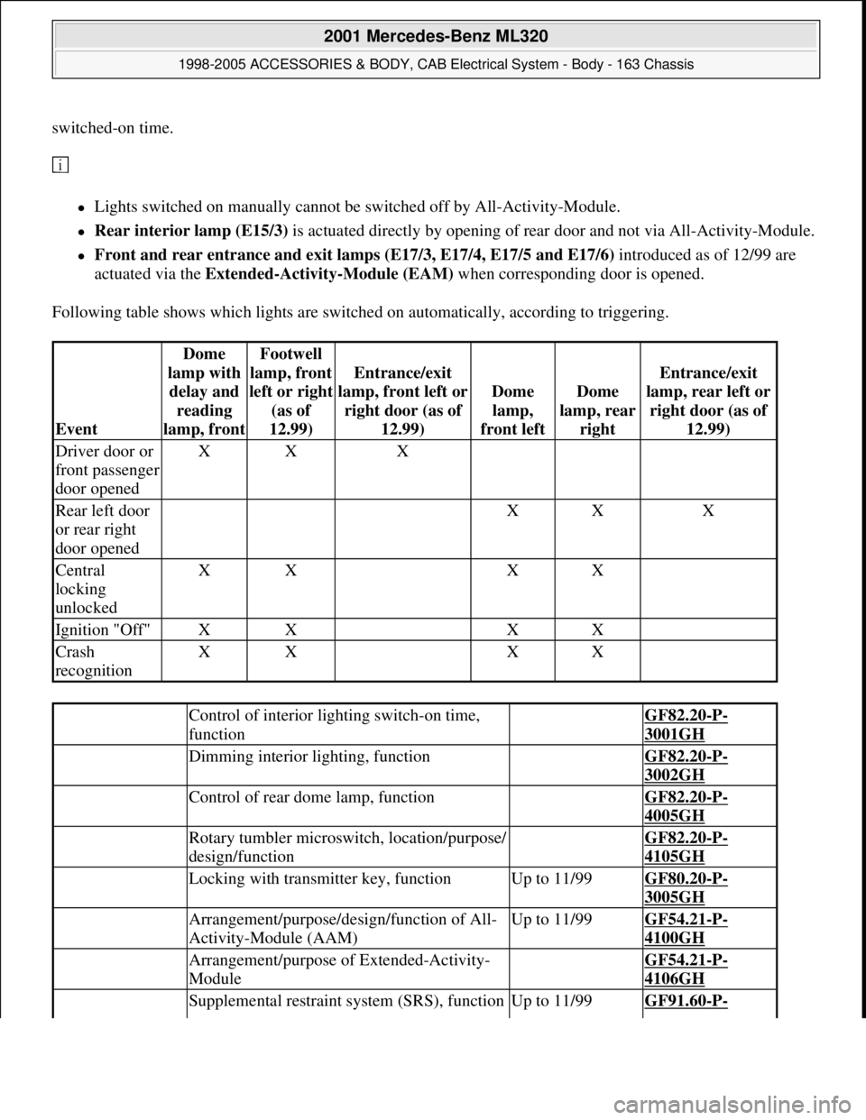
Following table shows which lights are switched on automatically, according to triggering.
Event
Dome
lamp with
delay and
reading
lamp, frontFootwell
lamp, front
left or ri
ght
(as of
12.99)
Entrance/exit
lamp, front left or
right door (as of
12.99)
Dome
lamp,
front leftDome
lamp, rear
right
Entrance/exit
lamp, rear left or
right door (as of
12.99)
Driver door or
front passenger
door openedXXX
Rear left door
or rear right
door opened XXX
Central
locking
unlockedXX XX
Ignition "Off"XX XX
Crash
recognitionXX XX
Control of interior lighting switch-on time,
function GF82.20-P-
3001GH
Dimming interior lighting, function GF82.20-P-
3002GH
Control of rear dome lamp, function GF82.20-P-
4005GH
Rotary tumbler microswitch, location/purpose/
design/function GF82.20-P-
4105GH
Locking with transmitter key, functionUp to 11/99GF80.20-P-
3005GH
Arrangement/purpose/design/function of All-
Activity-Module (AAM)Up to 11/99GF54.21-P-
4100GH
Arrangement/purpose of Extended-Activity-
Module GF54.21-P-
4106GH
Supplemental restraint system (SRS), functionUp to 11/99GF91.60-P-
2001 Mercedes-Benz ML320
1998-2005 ACCESSORIES & BODY, CAB Electrical System - Body - 163 Chassis
me
Saturday, October 02, 2010 3:30:04 PMPage 34 © 2006 Mitchell Repair Information Company, LLC.
Page 1533 of 4133
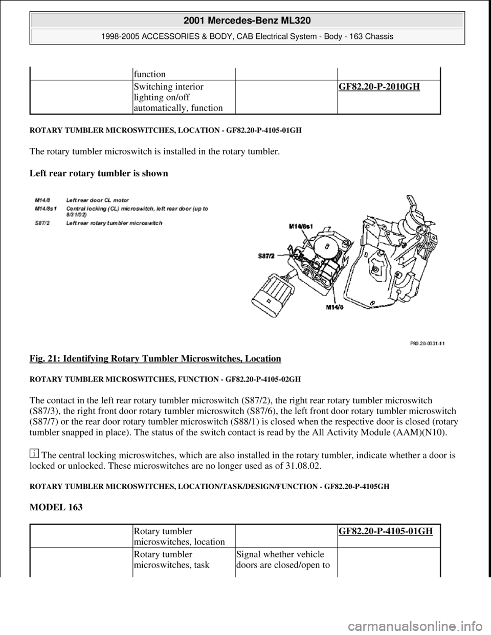
ROTARY TUMBLER MICROSWITCHES, LOCATION - GF82.20-P-4105-01GH
The rotary tumbler microswitch is installed in the rotary tumbler.
Left rear rotary tumbler is shown
Fig. 21: Identifying Rotary Tumbler Microswitches, Location
ROTARY TUMBLER MICROSWITCHES, FUNCTION - GF82.20-P-4105-02GH
The contact in the left rear rotary tumbler microswitch (S87/2), the right rear rotary tumbler microswitch
(S87/3), the right front door rotary tumbler microswitch (S87/6), the left front door rotary tumbler microswitch
(S87/7) or the rear door rotary tumbler microswitch (S88/1) is closed when the respective door is closed (rotary
tumbler snapped in place). The status of the switch contact is read by the All Activity Module (AAM)(N10).
The central locking microswitches, which are also installed in the rotary tumbler, indicate whether a door is
locked or unlocked. These microswitches are no longer used as of 31.08.02.
ROTARY TUMBLER MICROSWITCHES, LOCATION/TASK/DESIGN/FUNCTION - GF82.20-P-4105GH
MODEL 163
function
Switching interior
lighting on/off
automatically, function GF82.20-P-2010GH
Rotary tumbler
microswitches, location GF82.20-P-4105-01GH
Rotary tumbler
microswitches, taskSignal whether vehicle
doors are closed/open to
2001 Mercedes-Benz ML320
1998-2005 ACCESSORIES & BODY, CAB Electrical System - Body - 163 Chassis
me
Saturday, October 02, 2010 3:30:04 PMPage 38 © 2006 Mitchell Repair Information Company, LLC.
Page 1542 of 4133
SAFETY SHUTOFF (WSA) - FUNCTION - GF82.30-P-3005GH
MODEL 163 Applicable as of 1.9.00
Safety shutoff
The intermittent wipe function is interrupted when the vehicle comes to a complete stop and at least one of
the front doors is open. Any wipe cycle in progress is completed before wipers come to a halt.
Wiping resumes when both front doors are closed and/or the vehicle is put into motion.
The safety shutoff therefore only operates when the vehicle is at a complete stop. This ensures that the
intermittent wiping feature remains available during driving even if a door jamb switch is defective.
ANTI-LOCK PROTECTION FOR WIPER MOTOR, FUNCTION - GF82.30-P-4008GH
MODEL 163
The all-activity module(AAM) (N10) recognizes that the wiper motor (M6/1) is locked up because of the
absence of signals from the cam switch.
If signals are not recognized for longer than 1 s the front wiper motor relay (F1k17) is no longer actuated.
The anti-lock protection is only effective in the function interval wiping . In other wiper stages the AAM does
not have influence on the wiper motor.
RAIN SENSOR - FUNCTION - GF82.30-P-4103-02GH
location/purpose/design/function4100GH
as of 1.12.99GF54.21-P-
4100GK
Extended activity module,
location/purposeas of 1.12.99GF54.21-P-
4106GH
Windshield Intermittent
Wipe - Function GF82.30-P-3003GH
Wiper motor,
location/purpose/design/function GF82.30-P-
4104GH
All-activity module (AAM),
location/purpose/ design/functionup to 30.11.99GF54.21-P-
4100GH
as of 1.12.99GF54.21-P-
4100GK
2001 Mercedes-Benz ML320
1998-2005 ACCESSORIES & BODY, CAB Electrical System - Body - 163 Chassis
me
Saturday, October 02, 2010 3:30:04 PMPage 47 © 2006 Mitchell Repair Information Company, LLC.
Page 1683 of 4133
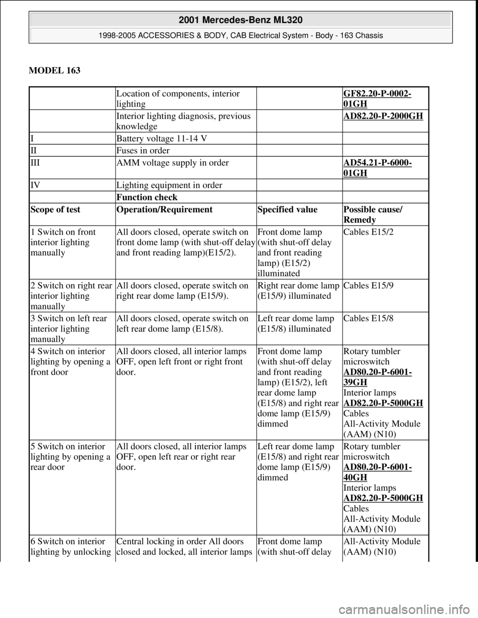
MODEL 163
Location of components, interior
lighting GF82.20-P-0002-
01GH
Interior lighting diagnosis, previous
knowledge AD82.20-P-2000GH
IBattery voltage 11-14 V
IIFuses in order
IIIAMM voltage supply in order AD54.21-P-6000-
01GH
IVLighting equipment in order
Function check
Scope of test Operation/Requirement Specified value Possible cause/
Remedy
1 Switch on front
interior lighting
manuallyAll doors closed, operate switch on
front dome lamp (with shut-off delay
and front reading lamp)(E15/2).Front dome lamp
(with shut-off delay
and front reading
lamp) (E15/2)
illuminatedCables E15/2
2 Switch on right rear
interior lighting
manuallyAll doors closed, operate switch on
right rear dome lamp (E15/9).Right rear dome lamp
(E15/9) illuminatedCables E15/9
3 Switch on left rear
interior lighting
manuallyAll doors closed, operate switch on
left rear dome lamp (E15/8).Left rear dome lamp
(E15/8) illuminatedCables E15/8
4 Switch on interior
lighting by opening a
front doorAll doors closed, all interior lamps
OFF, open left front or right front
door.Front dome lamp
(with shut-off delay
and front reading
lamp) (E15/2), left
rear dome lamp
(E15/8) and right rear
dome lamp (E15/9)
dimmedRotary tumbler
microswitch
AD80.20
-P-6001-
39GH
Interior lamps
AD82.20
-P-5000GH
Cables
All-Activity Module
(AAM) (N10)
5 Switch on interior
lighting by opening a
rear doorAll doors closed, all interior lamps
OFF, open left rear or right rear
door.Left rear dome lamp
(E15/8) and right rear
dome lamp (E15/9)
dimmedRotary tumbler
microswitch
AD80.20
-P-6001-
40GH
Interior lamps
AD82.20
-P-5000GH
Cables
All-Activity Module
(AAM) (N10)
6 Switch on interior
lighting by unlocking Central locking in order All doors
closed and locked, all interior lamps Front dome lamp
(with shut-off delay All-Activity Module
(AAM) (N10)
2001 Mercedes-Benz ML320
1998-2005 ACCESSORIES & BODY, CAB Electrical System - Body - 163 Chassis
me
Saturday, October 02, 2010 3:30:07 PMPage 188 © 2006 Mitchell Repair Information Company, LLC.
Page 1684 of 4133
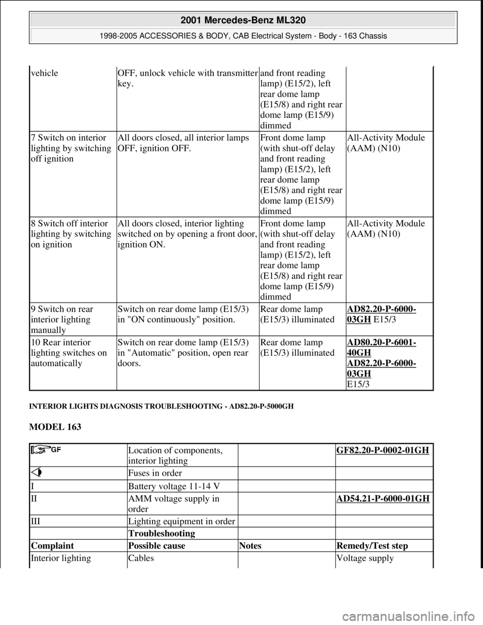
INTERIOR LIGHTS DIAGNOSIS TROUBLESHOOTING - AD82.20-P-5000GH
MODEL 163
vehicleOFF, unlock vehicle with transmitter
key.and front reading
lamp) (E15/2), left
rear dome lamp
(E15/8) and right rear
dome lamp (E15/9)
dimmed
7 Switch on interior
lighting by switching
off ignitionAll doors closed, all interior lamps
OFF, ignition OFF.Front dome lamp
(with shut-off delay
and front reading
lamp) (E15/2), left
rear dome lamp
(E15/8) and right rear
dome lamp (E15/9)
dimmedAll-Activity Module
(AAM) (N10)
8 Switch off interior
lighting by switching
on ignitionAll doors closed, interior lighting
switched on by opening a front door,
ignition ON.Front dome lamp
(with shut-off delay
and front reading
lamp) (E15/2), left
rear dome lamp
(E15/8) and right rear
dome lamp (E15/9)
dimmedAll-Activity Module
(AAM) (N10)
9 Switch on rear
interior lighting
manuallySwitch on rear dome lamp (E15/3)
in "ON continuously" position.Rear dome lamp
(E15/3) illuminatedAD82.20-P-6000-
03GH E15/3
10 Rear interior
lighting switches on
automaticallySwitch on rear dome lamp (E15/3)
in "Automatic" position, open rear
doors.Rear dome lamp
(E15/3) illuminatedAD80.20-P-6001-
40GH
AD82.20
-P-6000-
03GH
E15/3
Location of components,
interior lighting GF82.20-P-0002-01GH
Fuses in order
IBattery voltage 11-14 V
IIAMM voltage supply in
order AD54.21-P-6000-01GH
IIILighting equipment in order
Troubleshooting
Complaint Possible cause Notes Remedy/Test step
Interior lighting Cables Voltage supply
2001 Mercedes-Benz ML320
1998-2005 ACCESSORIES & BODY, CAB Electrical System - Body - 163 Chassis
me
Saturday, October 02, 2010 3:30:07 PMPage 189 © 2006 Mitchell Repair Information Company, LLC.
Page 1836 of 4133
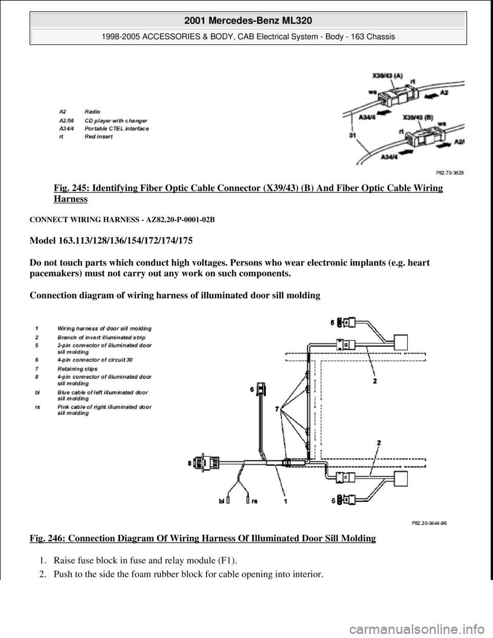
Fig. 245: Identifying Fiber Optic Cable Connector (X39/43) (B) And Fiber Optic Cable Wiring
Harness
CONNECT WIRING HARNESS - AZ82.20-P-0001-02B
Model 163.113/128/136/154/172/174/175
Do not touch parts which conduct high voltages. Persons who wear electronic implants (e.g. heart
pacemakers) must not carry out any work on such components.
Connection diagram of wiring harness of illuminated door sill molding
Fig. 246: Connection Diagram Of Wiring Harness Of Illuminated Door Sill Molding
1. Raise fuse block in fuse and relay module (F1).
2. Push to the side the foam rubber block for cable openin
g into interior.
2001 Mercedes-Benz ML320
1998-2005 ACCESSORIES & BODY, CAB Electrical System - Body - 163 Chassis
me
Saturday, October 02, 2010 3:30:11 PMPage 341 © 2006 Mitchell Repair Information Company, LLC.
Page 1838 of 4133
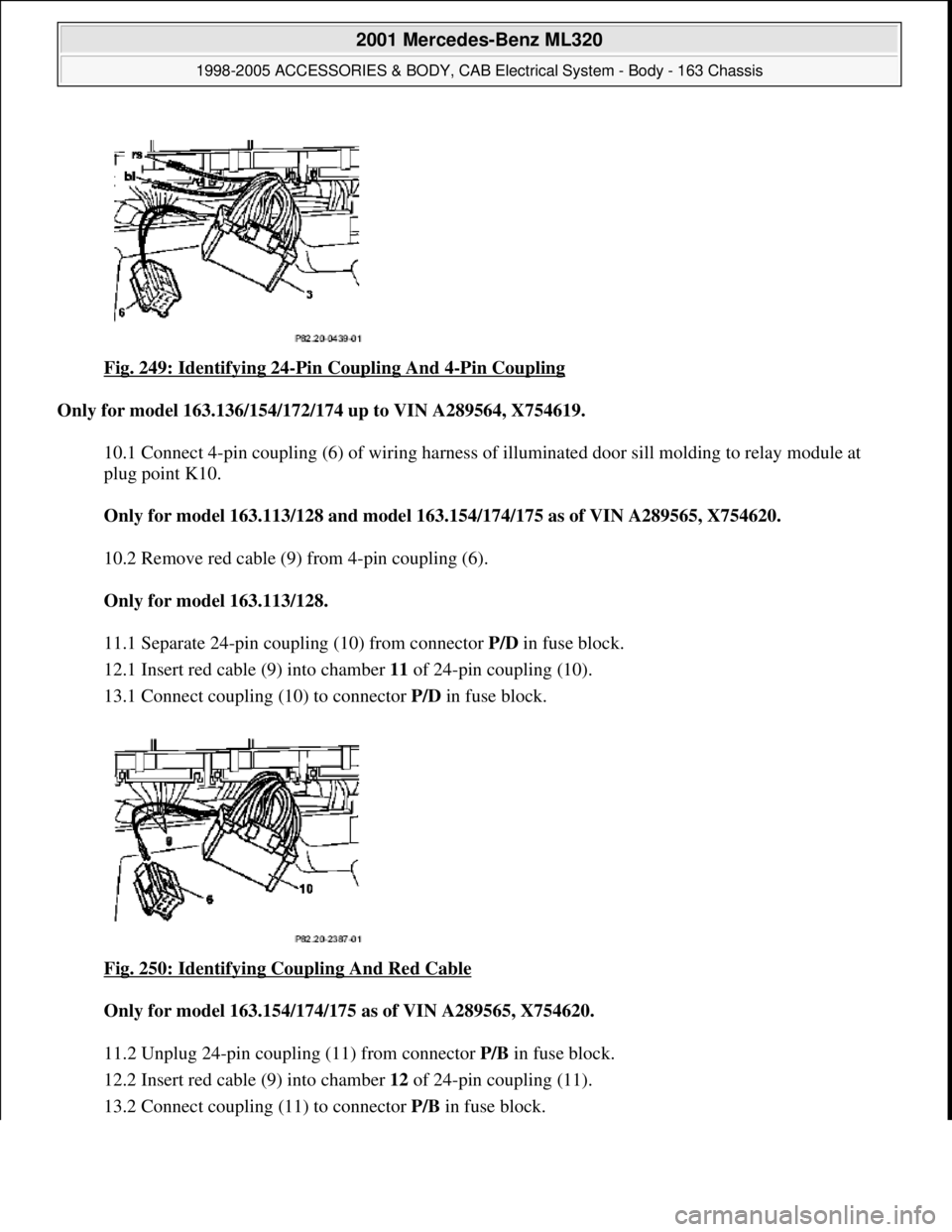
Fig. 249: Identifying 24-Pin Coupling And 4-Pin Coupling
Only for model 163.136/154/172/174 up to VIN A289564, X754619.
10.1 Connect 4-pin coupling (6) of wiring harness of illuminated door sill molding to relay module at
plug point K10.
Only for model 163.113/128 and mode l 163.154/174/175 as of VIN A289565, X754620.
10.2 Remove red cable (9) from 4-pin coupling (6).
Only for model 163.113/128.
11.1 Separate 24-pin coupli ng (10) from connector P/D in fuse block.
12.1 Insert red cable (9) into chamber 11 of 24-pin coupling (10).
13.1 Connect coupling (10) to connector P/D in fuse block.
Fig. 250: Identifying Coupling And Red Cable
Only for model 163.154/174/ 175 as of VIN A289565, X754620.
11.2 Unplug 24-pin coupling (11) from connector P/B in fuse block.
12.2 Insert red cable (9) into chamber 12 of 24-pin coupling (11).
13.2 Connect couplin
g (11) to connector P/Bin fuse block.
2001 Mercedes-Benz ML320
1998-2005 ACCESSORIES & BODY, CAB Electr ical System - Body - 163 Chassis
me
Saturday, October 02, 2010 3:30:11 PMPage 343 © 2006 Mitchell Repair Information Company, LLC.