Page 3576 of 4133

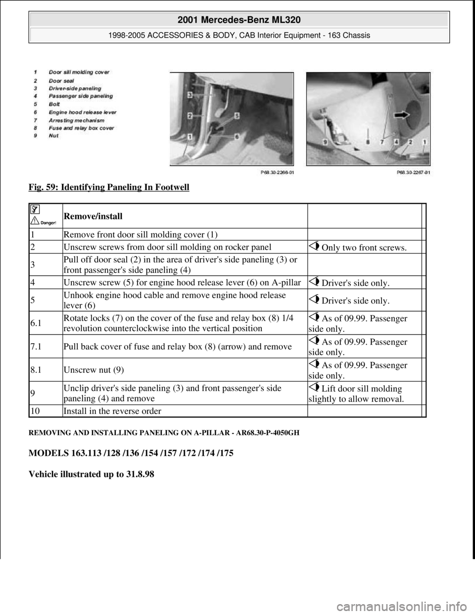
Fig. 59: Identifying Paneling In Footwell
REMOVING AND INSTALLING PANELING ON A-PILLAR - AR68.30-P-4050GH
MODELS 163.113 /128 /136 /154 /157 /172 /174 /175
Vehicle illustrated up to 31.8.98
Remove/install
1Remove front door sill molding cover (1)
2Unscrew screws from door sill molding on rocker panel Only two front screws.
3Pull off door seal (2) in the area of driver's side paneling (3) or
front passenger's side paneling (4)
4Unscrew screw (5) for engine hood release lever (6) on A-pillar Driver's side only.
5Unhook engine hood cable and remove engine hood release
lever (6) Driver's side only.
6.1Rotate locks (7) on the cover of the fuse and relay box (8) 1/4
revolution counterclockwise into the vertical position As of 09.99. Passenger
side only.
7.1Pull back cover of fuse and relay box (8) (arrow) and remove As of 09.99. Passenger
side only.
8.1Unscrew nut (9) As of 09.99. Passenger
side only.
9Unclip driver's side paneling (3) and front passenger's side
paneling (4) and remove Lift door sill molding
slightly to allow removal.
10Install in the reverse order
2001 Mercedes-Benz ML320
1998-2005 ACCESSORIES & BODY, CAB Interior Equipment - 163 Chassis
me
Saturday, October 02, 2010 3:35:22 PMPage 58 © 2006 Mitchell Repair Information Company, LLC.
Page 3752 of 4133

AR46.20-P-0600GH
Removing and installing rack-and-pinion steering
1.3.97
MODEL
163.113 /128 /136 /154 /157 /172 /174 /175
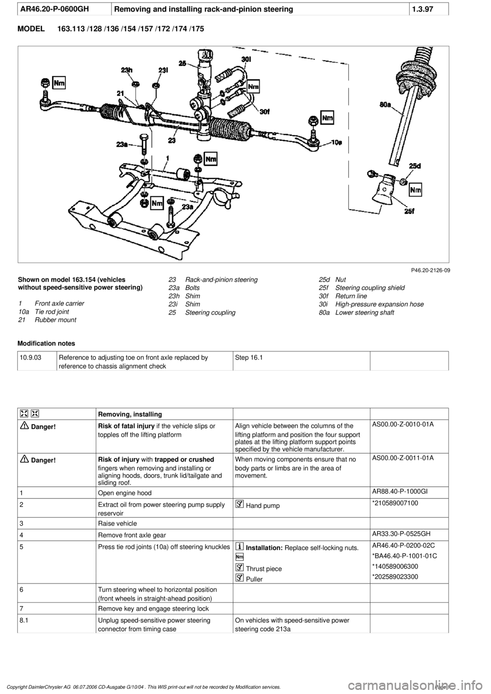
P46.20-2126-09
Shown on model 163.154 (vehicles
without speed-sensitive power steering)
1
Front axle carrier
10a
Tie rod joint
21
Rubber mount
25d
Nut
25f
Steering coupling shield
30f
Return line
30i
High-pressure expansion hose
80a
Lower steering shaft
23
Rack-and-pinion steering
23a
Bolts
23h
Shim
23i
Shim
25
Steering coupling
Modification notes
10.9.03
Reference to adjusting toe on front axle replaced by
reference to chassis alignment check
Step 16.1
Removing, installing
Danger!
Risk of fatal injury
if the vehicle slips or
topples off the lifting platform
Align vehicle between the columns of the
lifting platform and position the four support
plates
at the lifting platform support points
specified by the vehicle manufacturer.
AS00.00-Z-0010-01A
Danger!
Risk of injury
with
trapped or crushed
fingers when removing and installing or
aligning hoods, doors, trunk lid/tailgate and
sliding roof.
When moving components ensure that no
body parts or limbs are in the area of
movement.
AS00.00-Z-0011-01A
1
Open engine hood
AR88.40-P-1000GI
2
Extract oil from power steering pump supply
reservoir
Hand pump
*210589007100
3
Raise vehicle
4
Remove front axle gear
AR33.30-P-0525GH
5
Press tie rod joints (10a) off steering knuckles
Installation:
Replace self-locking nuts.
AR46.40-P-0200-02C
*BA46.40-P-1001-01C
Thrust piece
*140589006300
Puller
*202589023300
6
Turn steering wheel to horizontal position
(front wheels in straight-ahead position)
7
Remove key and engage steering lock
8.1
Unplug speed-sensitive power steering
connector from timing case
On vehicles with speed-sensitive power
steering code 213a
Copyright DaimlerChrysler AG 06.07.2006 CD-Ausgabe G/10/04 . This WIS print-out will not be recorde
d by Modification services.
Page 1
Page 3798 of 4133

GF91.29-P-0002GH
Electric seat adjustment with memory, function
14.7.99
MODEL
163 as of 1.1.00
with CODE (241) Memory for electrically adjustable left front seat
with CODE (242a) Memory for electrically adjustable right front seat
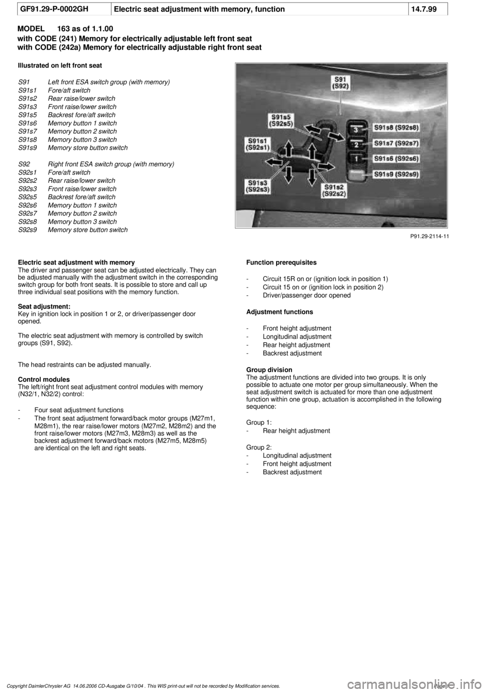
P91.29-2114-11
Illustrated on left front seat
S91
Left front ESA switch group (with memory)
S91s1
Fore/aft switch
S91s2
Rear raise/lower switch
S91s3
Front raise/lower switch
S91s5
Backrest fore/aft switch
S91s6
Memory button 1 switch
S91s7
Memory button 2 switch
S91s8
Memory button 3 switch
S91s9
Memory store button switch
S92
Right front ESA switch group (with memory)
S92s1
Fore/aft switch
S92s2
Rear raise/lower switch
S92s3
Front raise/lower switch
S92s5
Backrest fore/aft switch
S92s6
Memory button 1 switch
S92s7
Memory button 2 switch
S92s8
Memory button 3 switch
S92s9
Memory store button switch
Electric seat adjustment with memory
The driver and passenger seat can be adjusted electrically. They can
be adjusted manually with the adjustment switch in the corresponding
switch group for both front seats. It is possible to store and call up
three individual seat positions with the memory function.
Seat adjustment:
Key in ignition lock in position 1 or 2, or driver/passenger door
opened.
The electric seat adjustment with memory is controlled by switch
groups (S91, S92).
The head restraints can be adjusted manually.
Control modules
The left/right front seat adjustment control modules with memory
(N32/1, N32/2) control:
-
Four seat adjustment functions
-
The front seat adjustment forward/back motor groups (M27m1,
M28m1), the rear raise/lower motors (M27m2, M28m2) and the
front raise/lower motors (M27m3, M28m3) as well as the
backrest adjustment forward/back motors (M27m5, M28m5)
are identical on the left and right seats.
Function prerequisites
-
Circuit 15R on or (ignition lock in position 1)
-
Circuit 15 on or (ignition lock in position 2)
-
Driver/passenger door opened
Adjustment functions
-
Front height adjustment
-
Longitudinal adjustment
-
Rear height adjustment
-
Backrest adjustment
Group division
The adjustment functions are divided into two groups. It is only
possible to actuate one motor per group simultaneously. When the
seat adjustment switch is actuated for more than one adjustment
function within one group, actuation is accomplished in the following
sequence:
Group 1:
-
Rear height adjustment
Group 2:
-
Longitudinal adjustment
-
Front height adjustment
-
Backrest adjustment
Copyright DaimlerChrysler AG 14.06.2006 CD-Ausgabe G/10/04 . This WIS print-out will not be recorde
d by Modification services.
Page 1
Page 4081 of 4133
Fig. 41: Power Distribution Circuit (4 of 4)
POWER DOOR LOCKS
2001 Mercedes-Benz ML320
2001 SYSTEM WIRING DIAGRAMS Mercedes-Benz - ML320
me
Saturday, October 02, 2010 3:28:00 PMPage 83 © 2006 Mitchell Repair Information Company, LLC.
Page 4083 of 4133
Fig. 42: Power Door Locks Circuit
POWER MIRRORS
2001 Mercedes-Benz ML320
2001 SYSTEM WIRING DIAGRAMS Mercedes-Benz - ML320
me
Saturday, October 02, 2010 3:28:00 PMPage 85 © 2006 Mitchell Repair Information Company, LLC.