1997 MERCEDES-BENZ ML350 door lock
[x] Cancel search: door lockPage 2591 of 4133
AR47.20-P-1070M
Removing and installing fuel full-flow filter
24.8.99
ENGINE
612.963 in MODEL 163.113
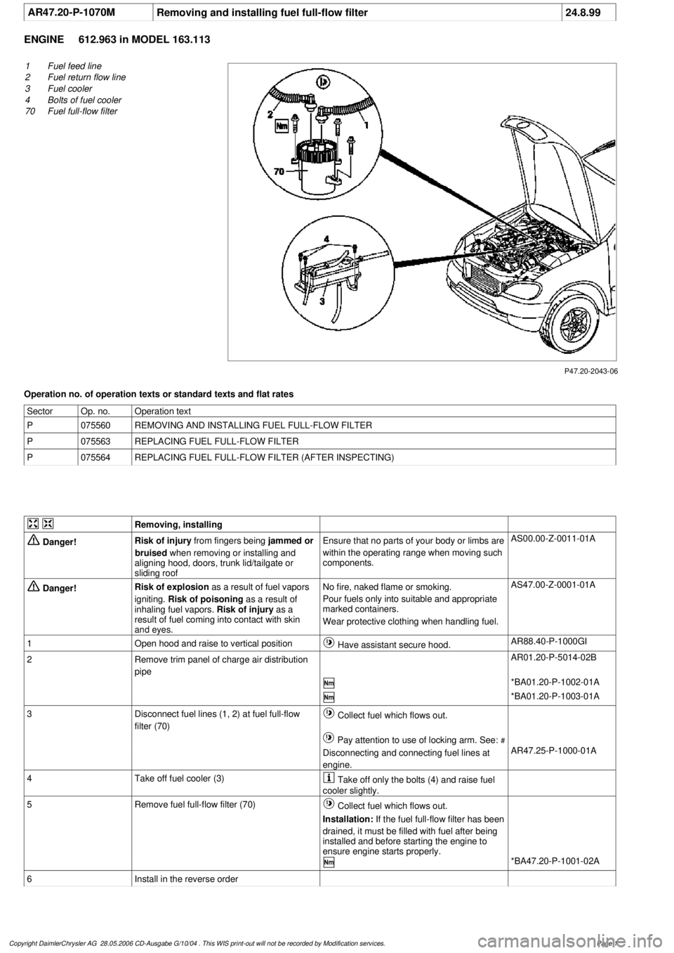
P47.20-2043-06
1
Fuel feed line
2
Fuel return flow line
3
Fuel cooler
4
Bolts of fuel cooler
70
Fuel full-flow filter
Operation no. of operation texts or standard texts and flat rates
Sector
Op. no.
Operation text
P
075560
REMOVING AND INSTALLING FUEL FULL-FLOW FILTER
P
075563
REPLACING FUEL FULL-FLOW FILTER
P
075564
REPLACING FUEL FULL-FLOW FILTER (AFTER INSPECTING)
Removing, installing
Danger!
Risk of injury
from fingers being
jammed or
bruised
when removing or installing and
aligning hood, doors, trunk lid/tailgate or
sliding roof
Ensure that no parts of your body or limbs are
within the operating range when moving such
components.
AS00.00-Z-0011-01A
Danger!
Risk of explosion
as a result of fuel vapors
igniting.
Risk of poisoning
as a result of
inhaling fuel vapors.
Risk of injury
as a
result of fuel coming into contact with skin
and eyes.
No fire, naked flame or smoking.
Pour fuels only into suitable and appropriate
marked containers.
Wear protective clothing when handling fuel.
AS47.00-Z-0001-01A
1
Open hood and raise to vertical position
Have assistant secure hood.
AR88.40-P-1000GI
2
Remove trim panel of charge air distribution
pipe
AR01.20-P-5014-02B
*BA01.20-P-1002-01A
*BA01.20-P-1003-01A
3
Disconnect fuel lines (1, 2) at fuel full-flow
filter (70)
Collect fuel which flows out.
Pay attention to use of locking arm. See:
#
Disconnecting and connecting fuel lines at
engine.
AR47.25-P-1000-01A
4
Take off fuel cooler (3)
Take off only the bolts (4) and raise fuel
cooler slightly.
5
Remove fuel full-flow filter (70)
Collect fuel which flows out.
Installation:
If the fuel full-flow filter has been
drained, it must be filled with fuel after being
installed and before starting the engine to
ensure engine starts properly.
*BA47.20-P-1001-02A
6
Install in the reverse order
Copyright DaimlerChrysler AG 28.05.2006 CD-Ausgabe G/10/04 . This WIS print-out will not be recorde
d by Modification services.
Page 1
Page 2656 of 4133
CONVERSION MEASURES RESULTING IN ALTERATION TO VEHICLE MODEL - AH00.10-P-1000-01A
Model 100, 107, 108, 109, 111, 112, 113, 114, 115, 116, 123, 124, 126, 129, 140, 163, 168, 170, 201, 202, 208,
210
We disapprove of all vehicle conversions resulting in an alteration to the model. A standard production vehicle
is a design entity which, upon installation of parts alien to the model, usually changes in a detrimental way.
Changes to important components influence the homogeneity of the vehicle in its entirety. For this reason we
have not investigated the details to be observed when performing such conversions. Such conversions can also
lead to changes on the vehicle which require new proof that the vehicle complies with legal requirements.
The main reasons for our disapproval are:
1. Subsequent installation of a component such as a more powerful engine may overload the remaining
components such as the transmission, brakes, axles, etc.
Body
Body - generalFG60AH60.00-Z-9999AZ
Front end and fire wallFG62AH62.00-Z-9999AZ
Side wallFG63AH63.00-Z-9999AZ
Rear wall and rear endFG64AH64.00-Z-9999AZ
RoofFG65AH65.00-Z-9999AZ
WindowsFG67AH67.00-Z-9999AZ
Interior equipmentFG68AH68.00-Z-9999AZ
DoorsFG72AH72.00-Z-9999AZ
Sliding roof, soft top, top
attachmentsFG77AH77.00-Z-9999AZ
Central locking,
convenience feature,
drive authorization
systemFG80AH80.00-Z-9999AZ
Electrical system bodyFG82AH82.00-Z-9999AZ
Climate controlFG83AH83.00-Z-9999AZ
Emergency equipment,
sanitary equipment,
galleyFG86AH86.00-Z-9999AZ
Detachable body
components, exterior
flapsFG88AH88.00-Z-9999AZ
Seats, bunks, restraint
systemsFG91AH91.00-Z-9999AZ
Body sealing, corrosion
protectionFG97AH97.00-Z-9999AZ
PaintworkFG98AH98.00-Z-9999AZ
2004 Mercedes-Benz ML350
1998-2005 GENINFO Overall vehicle - 163 Chassis
me
Saturday, October 02, 2010 3:47:44 PMPage 11 © 2006 Mitchell Repair Information Company, LLC.
Page 3162 of 4133
AUTOMATIC TRANSMISSION FLUIDS (ATF, SHEET 236.8) - BB00.40-P-0236-08A
Application in vehicles/major assemblies refer to ? Sheet 231.1 (passenger cars, crosscountry vehicles)
Sheet 231.2 (commercial vehicles)
LIQUID GREASE (NLGI GRADES 00/000) - BB00.40-P-0264-00A
Passenger car: Door lock striker bolts and locking eyes Commercial vehicles: Only for liquid grease
central lubrication systems from Willy Vogel AG, Berlin/Germany
Zwijnaarde, Belgium
Tor ATF 289De Oliebron B.V., Zwijndrecht, Netherlands
Product nameCustomer, town/country
Addinol ATF DIIEAddinol Lube Oil GmbH, Leuna, Germany
AgipATFIIE-(25367)ENI S.p.A. - Refining & Marketing Division, Rome,
Italy
Cepsa ATF SyntheticCepsa Lubricantes, S.A., Madrid, Spain
Elfmatic G2 SynTotal Lubrifiants, Paris la Defense Cedex, France
Finamatic S 6726Total Lubrifiants, Paris la Defense Cedex, France
Fuchs Titan ATF 5000 SLFuchs Petrolub AG, Mannheim, Germany
Gulf ATF SyntS.A. Espanola de Lubrificantes, Madrid, Spain
Mobil ATF SHCExxon Mobil Corporation, Fairfax, Virginia, USA
Motorex ATF IIE SyntheticBucher AG Langenthal, Langenthal/Switzerland
OMV ATF-SOMV, Refining & Marketing GmbH, Vienna, Austria
Panolin ATF SynthPanolin AG, Madetswil, Switzerland
Q8 Auto 14 SyntheticKuwait Petroleum, Hoogvliet RT, Netherlands
Ravenol Dexron II ERavensberger Schmierstoffvertrieb GmbH, Werther,
Germany
Repsol Matic SinteticoRepsol YPF Lubricantes y Especialidades, S.A.,
Mostoles-Madrid, Spain
Shell ATF XSShell International Petroleum Co., London, England
Teboil Fluid ES-MaxOy Teboil AB, Suomen Petrooli Oy, Hamina/Finland
Texamatic-S E-25453ChevronTexaco Technology Ghent,
Ghent/Zwijnaarde, Belgium
Total fluide Syn FETotal Lubrifiants, Paris la Defense Cedex, France
Wintershall ATF Dexron S E-25243SRS SchmierstoffVertrieb GmbH, Salzbergen,
Germany
Product nameCustomer, town/country
Acinol 8300 EPAxel Christiernsson bv, Fijnaart, Netherlands
Aral Fliebfett NAral Aktiengesellschaft, Hamburg, Germany
Autol Getriebefliebfett ZSAAgip Schmiertechnik GmbH, Wurzburg, Germany
2004 Mercedes-Benz ML350
1998-2005 GENINFO Overall vehicle - 163 Chassis
me
Saturday, October 02, 2010 3:47:56 PMPage 517 © 2006 Mitchell Repair Information Company, LLC.
Page 3193 of 4133
AR88.40-P-3020GH
Adjust engine hood
8.4.99
MODEL
163.113 /128 /136 /154 /157 /172 /174 /175
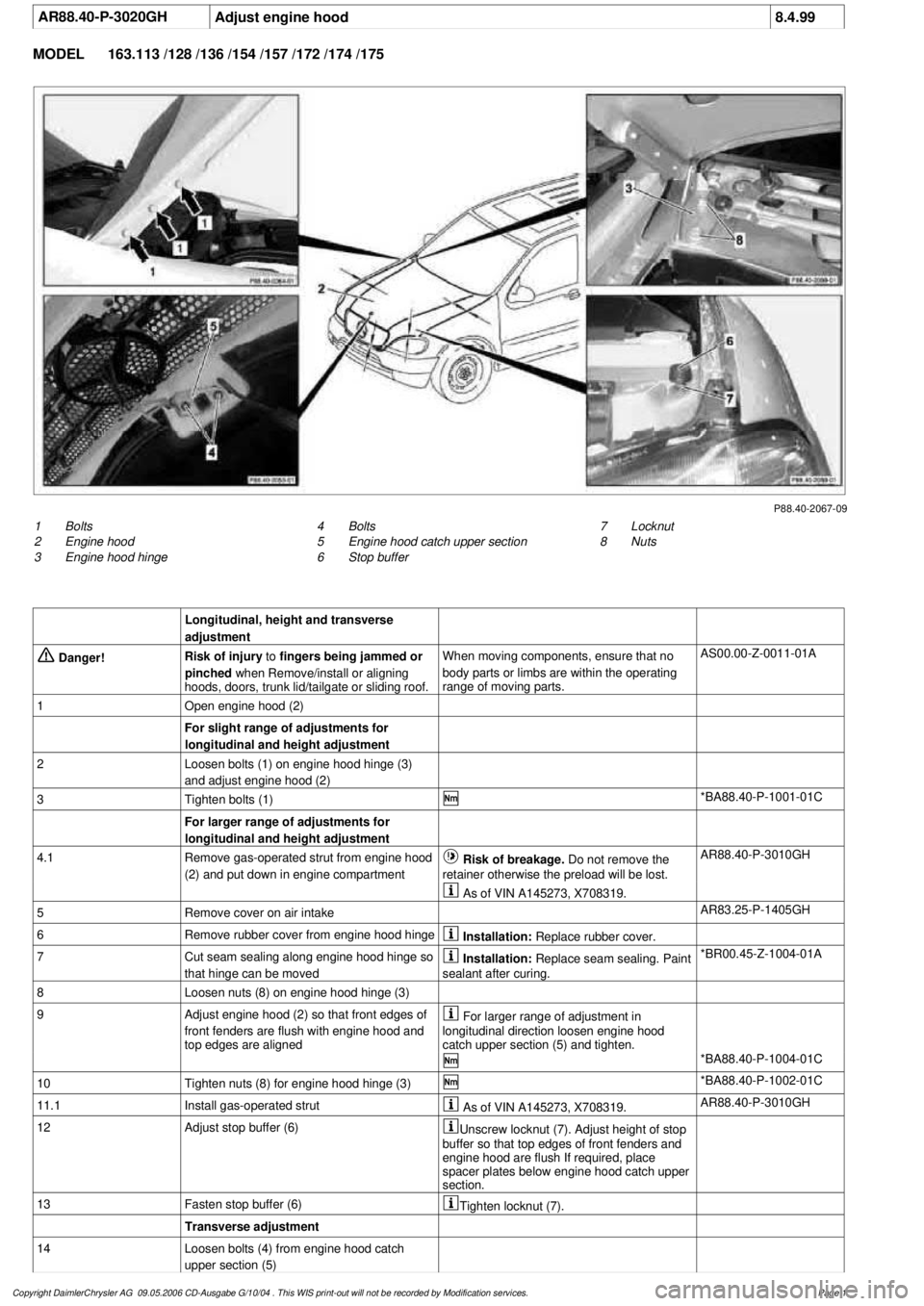
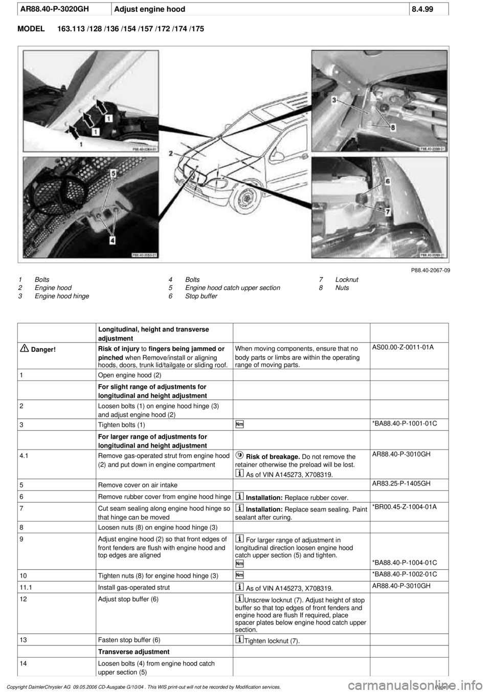
P88.40-2067-09
1
Bolts
2
Engine hood
3
Engine hood hinge
7
Locknut
8
Nuts
4
Bolts
5
Engine hood catch upper section
6
Stop buffer
Longitudinal, height and transverse
adjustment
Danger!
Risk of injury
to
fingers being jammed or
pinched
when Remove/install or aligning
hoods, doors, trunk lid/tailgate or sliding roof.
When moving components, ensure that no
body parts or limbs are within the operating
range of moving parts.
AS00.00-Z-0011-01A
1
Open engine hood (2)
For slight range of adjustments for
longitudinal and height adjustment
2
Loosen bolts (1) on engine hood hinge (3)
and adjust engine hood (2)
3
Tighten bolts (1)
*BA88.40-P-1001-01C
For larger range of adjustments for
longitudinal and height adjustment
4.1
Remove gas-operated strut from engine hood
(2) and put down in engine compartment
Risk of breakage. Do not remove the
retainer otherwise the preload will be lost.
AR88.40-P-3010GH
As of VIN A145273, X708319.
5
Remove cover on air intake
AR83.25-P-1405GH
6
Remove rubber cover from engine hood hinge
Installation:
Replace rubber cover.
7
Cut seam sealing along engine hood hinge so
that hinge can be moved
Installation:
Replace seam sealing. Paint
sealant after curing.
*BR00.45-Z-1004-01A
8
Loosen nuts (8) on engine hood hinge (3)
9
Adjust engine hood (2) so that front edges of
front fenders are flush with engine hood and
top edges are aligned
For larger range of adjustment in
longitudinal direction loosen engine hood
catch upper section (5) and tighten.
*BA88.40-P-1004-01C
10
Tighten nuts (8) for engine hood hinge (3)
*BA88.40-P-1002-01C
11.1
Install gas-operated strut
As of VIN A145273, X708319.
AR88.40-P-3010GH
12
Adjust stop buffer (6)
Unscrew locknut (7). Adjust height of stop
buffer so that top edges of front fenders and
engine hood are flush If required, place
spacer plates below engine hood catch upper
section.
13
Fasten stop buffer (6)
Tighten locknut (7).
Transverse adjustment
14
Loosen bolts (4) from engine hood catch
upper section (5)
Copyright DaimlerChrysler AG 09.05.2006 CD-Ausgabe G/10/04 . This WIS print-out will not be recorde
d by Modification services.
Page 1
Page 3195 of 4133
AR88.40-P-3020GH
Adjust engine hood
8.4.99
MODEL
163.113 /128 /136 /154 /157 /172 /174 /175
P88.40-2067-09
1
Bolts
2
Engine hood
3
Engine hood hinge
7
Locknut
8
Nuts
4
Bolts
5
Engine hood catch upper section
6
Stop buffer
Longitudinal, height and transverse
adjustment
Danger!
Risk of injury
to
fingers being jammed or
pinched
when Remove/install or aligning
hoods, doors, trunk lid/tailgate or sliding roof.
When moving components, ensure that no
body parts or limbs are within the operating
range of moving parts.
AS00.00-Z-0011-01A
1
Open engine hood (2)
For slight range of adjustments for
longitudinal and height adjustment
2
Loosen bolts (1) on engine hood hinge (3)
and adjust engine hood (2)
3
Tighten bolts (1)
*BA88.40-P-1001-01C
For larger range of adjustments for
longitudinal and height adjustment
4.1
Remove gas-operated strut from engine hood
(2) and put down in engine compartment
Risk of breakage. Do not remove the
retainer otherwise the preload will be lost.
AR88.40-P-3010GH
As of VIN A145273, X708319.
5
Remove cover on air intake
AR83.25-P-1405GH
6
Remove rubber cover from engine hood hinge
Installation:
Replace rubber cover.
7
Cut seam sealing along engine hood hinge so
that hinge can be moved
Installation:
Replace seam sealing. Paint
sealant after curing.
*BR00.45-Z-1004-01A
8
Loosen nuts (8) on engine hood hinge (3)
9
Adjust engine hood (2) so that front edges of
front fenders are flush with engine hood and
top edges are aligned
For larger range of adjustment in
longitudinal direction loosen engine hood
catch upper section (5) and tighten.
*BA88.40-P-1004-01C
10
Tighten nuts (8) for engine hood hinge (3)
*BA88.40-P-1002-01C
11.1
Install gas-operated strut
As of VIN A145273, X708319.
AR88.40-P-3010GH
12
Adjust stop buffer (6)
Unscrew locknut (7). Adjust height of stop
buffer so that top edges of front fenders and
engine hood are flush If required, place
spacer plates below engine hood catch upper
section.
13
Fasten stop buffer (6)
Tighten locknut (7).
Transverse adjustment
14
Loosen bolts (4) from engine hood catch
upper section (5)
Copyright DaimlerChrysler AG 09.05.2006 CD-Ausgabe G/10/04 . This WIS print-out will not be recorde
d by Modification services.
Page 1
Page 3214 of 4133
Mode control knob controls air distribution throughout the passenger compartment. Air distribution doors are
controlled by cables activated by the mode control knob. See Fig. 1
. Four mode positions are available with
detents in-between to adjust airflow for personal comfort.
Defrost
Set mode control knob to 12-o'clock position. Air will exit from defrost outlets and side window vents.
Vent
Set mode control knob to 9-o'clock position. Air will exit from instrument panel outlets.
Floor
Set mode control knob to 6-o'clock position. Air will exit from floor outlets.
Blend/Bi-Level
Set mode control knob to 3-o'clock position. Air will exit from defrost, instrument panel, and floor outlets.
TEMPERATURE CONTROL KNOB
Air temperature is controlled by a variable resistor rotary control switch. See Fig. 1 . Switch receives voltage
signal and depending upon position, controls voltage signal sent to air mix damper door motor. See Fig. 2
.
Volta
ge controls position of motor for heating and cooling.
2001 Mercedes-Benz ML320
2000-01 MANUAL A/C-HEATER SYSTEMS ML 320, ML 430 & ML 55
me
Saturday, October 02, 2010 3:25:10 PMPage 3 © 2006 Mitchell Repair Information Company, LLC.
Page 3542 of 4133
Jacket tube
REMOVING AND INSTALLING CENTER AIR NOZZLE - AR68.10-P-1150GH
MODEL 163.113 /128 /136 /154 /157 /172 /174 /175
panel (3)
7Unscrew screws (11) for steering column
(10) from instrument panel carrier (3) *BA46.10-P-
1006-03C
8Remove nuts (12) for steering column (10)
from instrument panel carrier (3) *BA46.10-P-
1007-03C
9Unscrew screws (4) for instrument panel
carrier (3) from middle tunnel
10Disconnect connector from steering column
height adjustment switch (20)
11Disconnect connector from MB
immobilizer switching unit (18)
12Disconnect connector from steering/ignition
switch (19)
13Disconnect wiring harness (15) from
instrument panel carrier Installation:Ensure that wiring
harness is routed correctly on
instrument panel carrier.
14Remove wiper system AR82.30-P-
6400GH
15Unscrew nuts for instrument panel carrier
(3) on firewall Installation: Install new self-
locking nuts.
16Remove caps on A-pillar (1)
17Unscrew screws (2) for instrument panel
carrier (3) from A-pillar
18
Remove instrument panel carrier (3) and
take out of passenger compartment to side
through passenger doorBe careful not to damage center
console when removing and
installing.
19Install in the reverse order
NumberDesignationMODEL Series
163
BA46.10-P-1006-
03CScrew for jacket tube on upper instrument panel carrierNm20
BA46.10-P-1007-
03CJacket tube collar nut on instrument panel carrier at
bottomNm18
2001 Mercedes-Benz ML320
1998-2005 ACCESSORIES & BODY, CAB Interior Equipment - 163 Chassis
me
Saturday, October 02, 2010 3:35:21 PMPage 24 © 2006 Mitchell Repair Information Company, LLC.
Page 3561 of 4133
1Remove front seats 1000GH
2.1Remove bass module speaker Only with Sound-System, Code 810.AR82.62-P-
7839GH
3.1Remove control module for
emergency call system Only with emergency call system E-Call,
Code 349.AR82.95-P-
0008GH
4Remove bench 1/3 bench seat, up to 31.8.99.AR91.12-P-
1010GH
40% bench seat, as of 01.9.99.AR91.12-P-
1010GI
2/3 bench seat, up to 31.8.99.AR91.12-P-
1010GJ
60% bench seat, as of 01.9.99.AR91.12-P-
1010GK
5Remove rear seat anchors (2) Up to 31.8.99, unscrew internal Torx drive
bolts (3).
Torx bit setFig. 24
6Remove center console (4) AR68.20-P-
2000GH
7Remove cover below instrument
panel on left (6) AR68.10-P-
1500GH
8Remove cover below instrument
panel on right (5) Up to 31.8.99.AR68.10-P-
1520GH
As of 01.9.99.AR68.10-P-
1520GI
9Unscrew plastic nuts (11) in right
footwell
10Remove condensate water drain
hose from heater housing
11
Remove door sill molding on
right (9) and door sill molding on
left (10)
AR68.30-P-
4100GH
12
Remove paneling in footwell on
right (7) and paneling in footwell
on left (8)
AR68.30-P-
4010GH
13Remove insulating mat under the
center console
14Remove air duct for ventilation in
the rear
15Remove radio AR82.60-P-
7502EA
16Disconnect all the electrical
connectors and lay aside
17Detach shift-lock cable at the
electronic selector module
2001 Mercedes-Benz ML320
1998-2005 ACCESSORIES & BODY, CAB Interior Equipment - 163 Chassis
me
Saturday, October 02, 2010 3:35:22 PMPage 43 © 2006 Mitchell Repair Information Company, LLC.