1997 MERCEDES-BENZ ML320 automatic transmission
[x] Cancel search: automatic transmissionPage 1913 of 4133
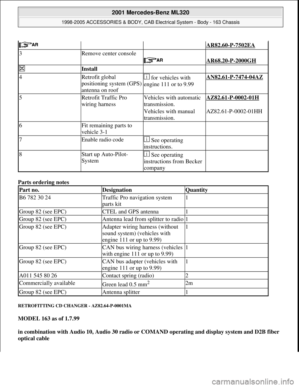
Parts ordering notes
RETROFITTING CD CHANGER - AZ82.64-P-0001MA
MODEL 163 as of 1.7.99
in combination with Audio 10, Audio 30 radio or COMAND operating and display system and D2B fiber
optical cable
AR82.60-P-7502EA
3Remove center console
AR68.20-P-2000GH
Install
4Retrofit global
positioning system (GPS)
antenna on roof for vehicles with
engine 111 or to 9.99AN82.61-P-7474-04AZ
5Retrofit Traffic Pro
wiring harnessVehicles with automatic
transmission.AZ82.61-P-0002-01H
Vehicles with manual
transmission.AZ82.61-P-0002-01HH
6Fit remaining parts to
vehicle 3-1
7Enable radio code See operating
instructions.
8Start up Auto-Pilot-
System See operating
instructions from Becker
company
Part no.DesignationQuantity
B6 782 30 24Traffic Pro navigation system
parts kit1
Group 82 (see EPC)CTEL and GPS antenna1
Group 82 (see EPC)Antenna lead from splitter to radio1
Group 82 (see EPC)Adapter wiring harness (without
sound system) (vehicles with
engine 111 or up to 9.99)1
Group 82 (see EPC)CAN bus wiring harness (vehicles
with engine 111 or up to 9.99)1
Group 82 (see EPC)CAN bus adapter (vehicles with
engine 111 or up to 9.99)1
A011 545 80 26Contact spring (radio)2
Commercially availableGreen lead 0.5 mm2 2m
Group 82 (see EPC)Antenna splitter1
2001 Mercedes-Benz ML320
1998-2005 ACCESSORIES & BODY, CAB Electrical System - Body - 163 Chassis
me
Saturday, October 02, 2010 3:30:13 PMPage 418 © 2006 Mitchell Repair Information Company, LLC.
Page 2172 of 4133
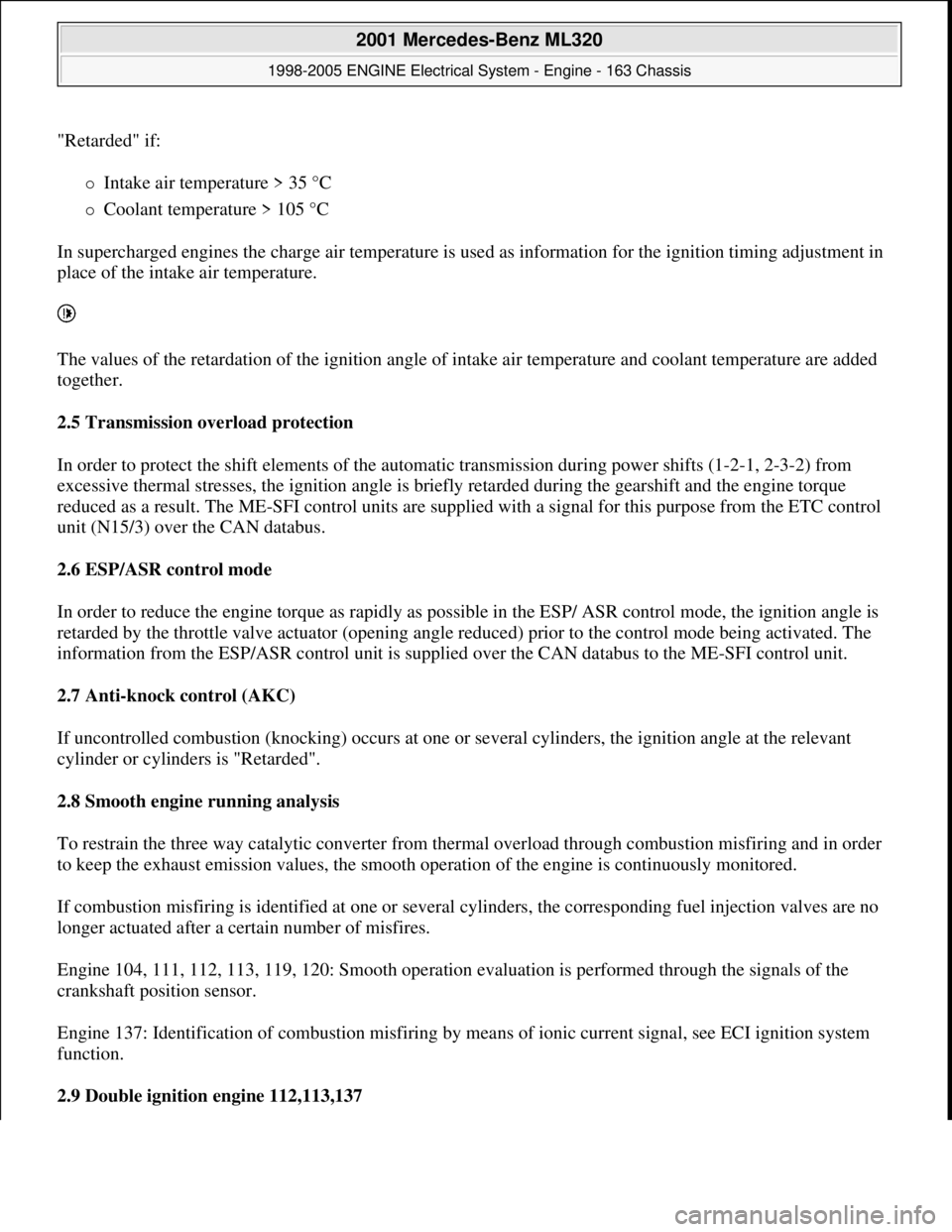
"Retarded" if:
Intake air temperature > 35 °C
Coolant temperature > 105 °C
In supercharged engines the charge air temperature is used as information for the ignition timing adjustment in
place of the intake air temperature.
The values of the retardation of the ignition angle of intake air temperature and coolant temperature are added
together.
2.5 Transmission overload protection
In order to protect the shift elements of the automatic transmission during power shifts (1-2-1, 2-3-2) from
excessive thermal stresses, the ignition angle is briefly retarded during the gearshift and the engine torque
reduced as a result. The ME-SFI control units are supplied with a signal for this purpose from the ETC control
unit (N15/3) over the CAN databus.
2.6 ESP/ASR control mode
In order to reduce the engine torque as rapidly as possible in the ESP/ ASR control mode, the ignition angle is
retarded by the throttle valve actuator (opening angle reduced) prior to the control mode being activated. The
information from the ESP/ASR control unit is supplied over the CAN databus to the ME-SFI control unit.
2.7 Anti-knock control (AKC)
If uncontrolled combustion (knocking) occurs at one or several cylinders, the ignition angle at the relevant
cylinder or cylinders is "Retarded".
2.8 Smooth engine running analysis
To restrain the three way catalytic converter from thermal overload through combustion misfiring and in order
to keep the exhaust emission values, the smooth operation of the engine is continuously monitored.
If combustion misfiring is identified at one or several cylinders, the corresponding fuel injection valves are no
longer actuated after a certain number of misfires.
Engine 104, 111, 112, 113, 119, 120: Smooth operation evaluation is performed through the signals of the
crankshaft position sensor.
Engine 137: Identification of combustion misfiring by means of ionic current signal, see ECI ignition system
function.
2.9 Double ignition engine 112,113,137
2001 Mercedes-Benz ML320
1998-2005 ENGINE Electrical System - Engine - 163 Chassis
me
Saturday, October 02, 2010 3:18:54 PMPage 18 © 2006 Mitchell Repair Information Company, LLC.
Page 2174 of 4133
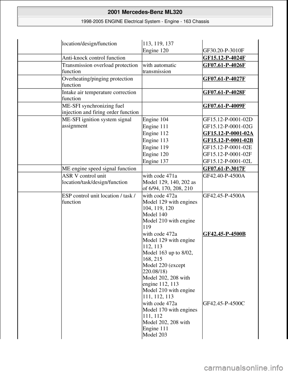
location/design/function113, 119, 137
Engine 120GF30.20-P-3010F
Anti-knock control function GF15.12-P-4024F
Transmission overload protection
functionwith automatic
transmissionGF07.61-P-4026F
Overheating/pinging protection
function GF07.61-P-4027F
Intake air temperature correction
function GF07.61-P-4028F
ME-SFI synchronizing fuel
injection and firing order function GF07.61-P-4009F
ME-SFI ignition system signal
assignmentEngine 104GF15.12-P-0001-02D
Engine 111GF15.12-P-0001-02G
Engine 112GF15.12-P-0001-02A
Engine 113GF15.12-P-0001-02B
Engine 119GF15.12-P-0001-02E
Engine 120GF15.12-P-0001-02F
Engine 137GF15.12-P-0001-02L
ME engine speed signal function GF07.61-P-3017F
ASR V control unit
location/task/design/functionwith code 471a
Model 129, 140, 202 as
of 6/94, 170, 208, 210GF42.40-P-4500A
ESP control unit location / task /
functionwith code 472a
Model 129 with engines
104, 119, 120
Model 140
Model 210 with engine
119GF42.45-P-4500A
with code 472a
Model 129 with engine
112, 113
Model 163 up to 8/02,
168, 215
Model 220 (except
220.08/18)
Model 202, 208 with
engine 112, 113
Model 210 with engine
111, 112, 113GF42.45-P-4500B
with code 472a
Model 170 with engines
111, 112
Model 202, 208 with
Engine 111
Model 203GF42.45-P-4500C
2001 Mercedes-Benz ML320
1998-2005 ENGINE Electrical System - Engine - 163 Chassis
me
Saturday, October 02, 2010 3:18:54 PMPage 20 © 2006 Mitchell Repair Information Company, LLC.
Page 2181 of 4133
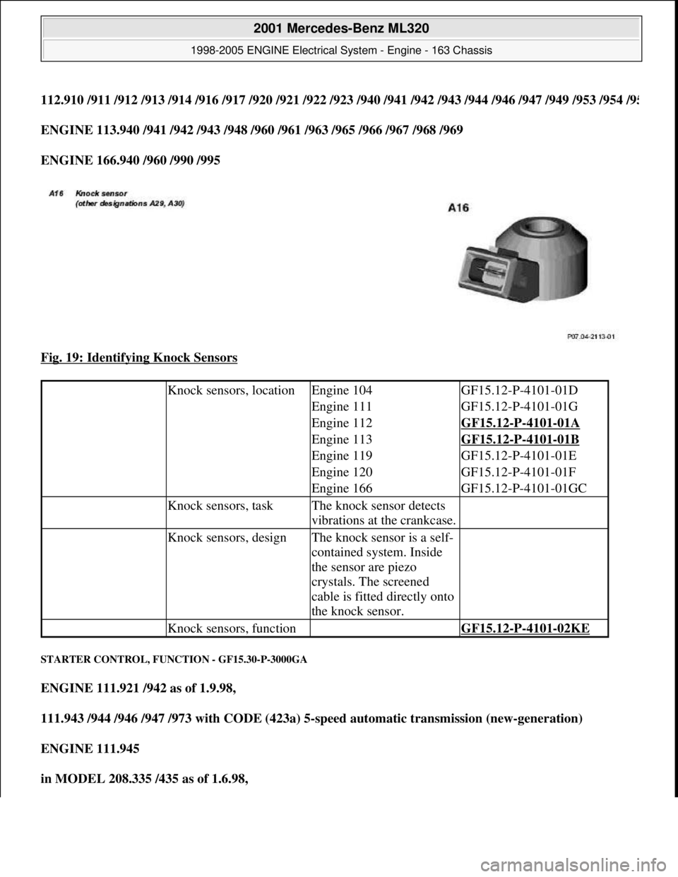
112.910 /911 /912 /913 /914 /916 /917 /920 /921 /922 /923 /940 /941 /942 /943 /944 /946 /947 /949 /953 /954 /95
ENGINE 113.940 /941 /942 /943 /948 /960 /961 /963 /965 /966 /967 /968 /969
ENGINE 166.940 /960 /990 /995
Fig. 19: Identifying Knock Sensors
STARTER CONTROL, FUNCTION - GF15.30-P-3000GA
ENGINE 111.921 /942 as of 1.9.98,
111.943 /944 /946 /947 /973 with CODE (423a) 5-speed automatic transmission (new-generation)
ENGINE 111.945
in MODEL 208.335 /435 as of 1.6.98,
Knock sensors, locationEngine 104GF15.12-P-4101-01D
Engine 111GF15.12-P-4101-01G
Engine 112GF15.12-P-4101-01A
Engine 113GF15.12-P-4101-01B
Engine 119GF15.12-P-4101-01E
Engine 120GF15.12-P-4101-01F
Engine 166GF15.12-P-4101-01GC
Knock sensors, taskThe knock sensor detects
vibrations at the crankcase.
Knock sensors, designThe knock sensor is a self-
contained system. Inside
the sensor are piezo
crystals. The screened
cable is fitted directly onto
the knock sensor.
Knock sensors, function GF15.12-P-4101-02KE
2001 Mercedes-Benz ML320
1998-2005 ENGINE Electrical System - Engine - 163 Chassis
me
Saturday, October 02, 2010 3:18:54 PMPage 27 © 2006 Mitchell Repair Information Company, LLC.
Page 2182 of 4133
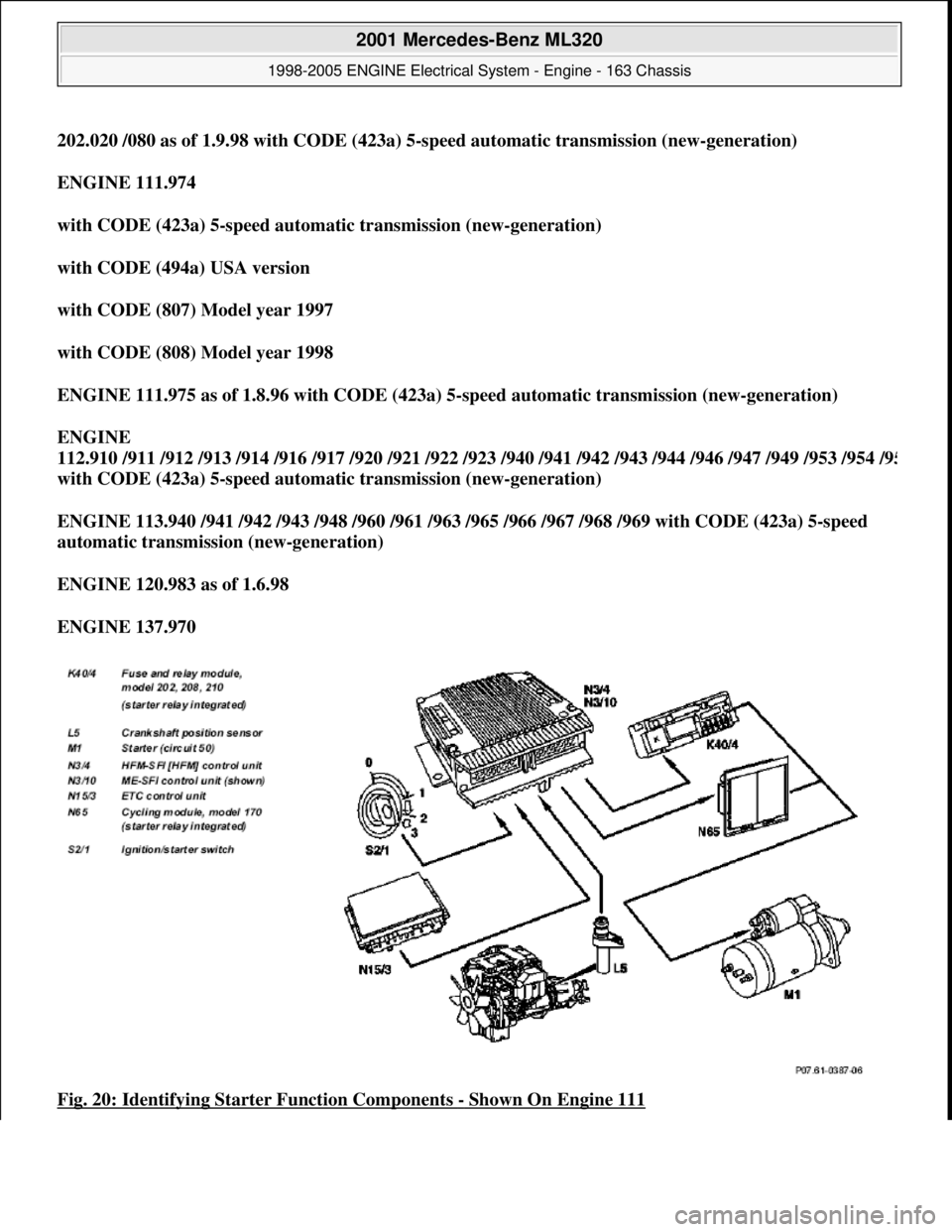
202.020 /080 as of 1.9.98 with CODE (423a) 5-speed automatic transmission (new-generation)
ENGINE 111.974
with CODE (423a) 5-speed automatic transmission (new-generation)
with CODE (494a) USA version
with CODE (807) Model year 1997
with CODE (808) Model year 1998
ENGINE 111.975 as of 1.8.96 with CODE (423a) 5-speed automatic transmission (new-generation)
ENGINE
112.910 /911 /912 /913 /914 /916 /917 /920 /921 /922 /923 /940 /941 /942 /943 /944 /946 /947 /949 /953 /954 /9
5
with CODE (423a) 5-speed automatic transmission (new-generation)
ENGINE 113.940 /941 /942 /943 /948 /960 /961 /963 /965 /966 /967 /968 /969 with CODE (423a) 5-speed
automatic transmission (new-generation)
ENGINE 120.983 as of 1.6.98
ENGINE 137.970
Fig. 20: Identifying Starter Function Components
- Shown On Engine 111
2001 Mercedes-Benz ML320
1998-2005 ENGINE Electrical System - Engine - 163 Chassis
me
Saturday, October 02, 2010 3:18:54 PMPage 28 © 2006 Mitchell Repair Information Company, LLC.
Page 2183 of 4133
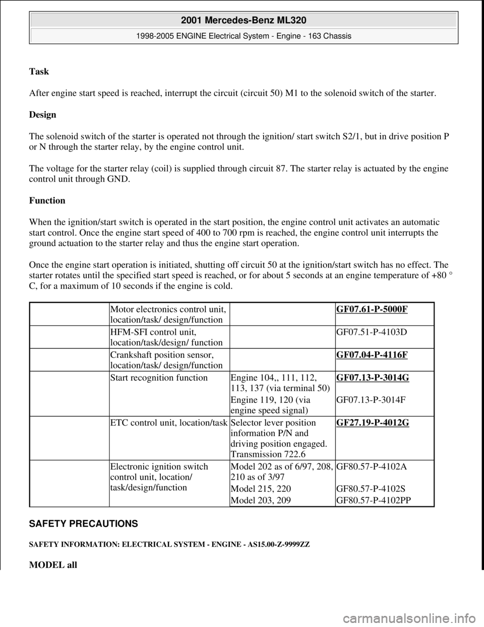
Task
After engine start speed is reached, interrupt the circuit (circuit 50) M1 to the solenoid switch of the starter.
Design
The solenoid switch of the starter is operated not through the ignition/ start switch S2/1, but in drive position P
or N through the starter relay, by the engine control unit.
The voltage for the starter relay (coil) is supplied through circuit 87. The starter relay is actuated by the engine
control unit through GND.
Function
When the ignition/start switch is operated in the start position, the engine control unit activates an automatic
start control. Once the engine start speed of 400 to 700 rpm is reached, the engine control unit interrupts the
ground actuation to the starter relay and thus the engine start operation.
Once the engine start operation is initiated, shutting off circuit 50 at the ignition/start switch has no effect. The
starter rotates until the specified start speed is reached, or for about 5 seconds at an engine temperature of +80 °
C, for a maximum of 10 seconds if the engine is cold.
SAFETY PRECAUTIONS
SAFETY INFORMATION: ELECTRICAL SYSTEM - ENGINE - AS15.00-Z-9999ZZ
MODEL all
Motor electronics control unit,
location/task/ design/function GF07.61-P-5000F
HFM-SFI control unit,
location/task/design/ function GF07.51-P-4103D
Crankshaft position sensor,
location/task/ design/function GF07.04-P-4116F
Start recognition functionEngine 104,, 111, 112,
113, 137 (via terminal 50)GF07.13-P-3014G
Engine 119, 120 (via
engine speed signal)GF07.13-P-3014F
ETC control unit, location/taskSelector lever position
information P/N and
driving position engaged.
Transmission 722.6GF27.19-P-4012G
Electronic ignition switch
control unit, location/
task/design/functionModel 202 as of 6/97, 208,
210 as of 3/97GF80.57-P-4102A
Model 215, 220GF80.57-P-4102S
Model 203, 209GF80.57-P-4102PP
2001 Mercedes-Benz ML320
1998-2005 ENGINE Electrical System - Engine - 163 Chassis
me
Saturday, October 02, 2010 3:18:54 PMPage 29 © 2006 Mitchell Repair Information Company, LLC.
Page 2205 of 4133
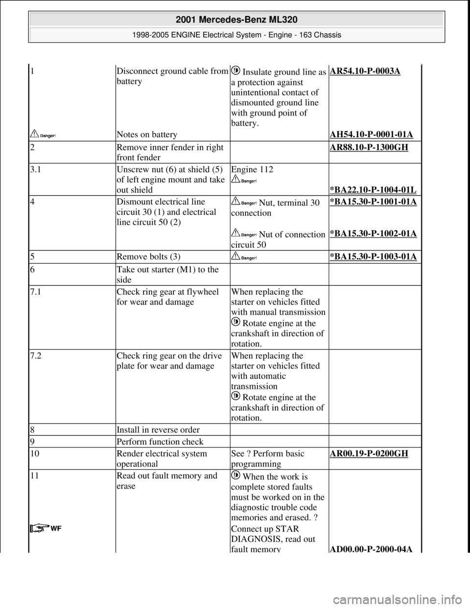
1Disconnect ground cable from
battery Insulate ground line as
a protection against
unintentional contact of
dismounted ground line
with ground point of
battery.AR54.10-P-0003A
Notes on battery AH54.10-P-0001-01A
2Remove inner fender in right
front fender AR88.10-P-1300GH
3.1Unscrew nut (6) at shield (5)
of left engine mount and take
out shieldEngine 112
*BA22.10-P-1004-01L
4Dismount electrical line
circuit 30 (1) and electrical
line circuit 50 (2) Nut, terminal 30
connection*BA15.30-P-1001-01A
Nut of connection
circuit 50*BA15.30-P-1002-01A
5Remove bolts (3) *BA15.30-P-1003-01A
6Take out starter (M1) to the
side
7.1Check ring gear at flywheel
for wear and damageWhen replacing the
starter on vehicles fitted
with manual transmission
Rotate engine at the
crankshaft in direction of
rotation.
7.2Check ring gear on the drive
plate for wear and damageWhen replacing the
starter on vehicles fitted
with automatic
transmission
Rotate engine at the
crankshaft in direction of
rotation.
8Install in reverse order
9Perform function check
10Render electrical system
operationalSee ? Perform basic
programmingAR00.19-P-0200GH
11Read out fault memory and
erase When the work is
complete stored faults
must be worked on in the
diagnostic trouble code
memories and erased. ?
Connect up STAR
DIAGNOSIS, read out
fault memory
AD00.00-P-2000-04A
2001 Mercedes-Benz ML320
1998-2005 ENGINE Electrical System - Engine - 163 Chassis
me
Saturday, October 02, 2010 3:18:54 PMPage 51 © 2006 Mitchell Repair Information Company, LLC.
Page 2413 of 4133
two bottom bolts at transmission bell.
*BA27.40-P-
1008-01A
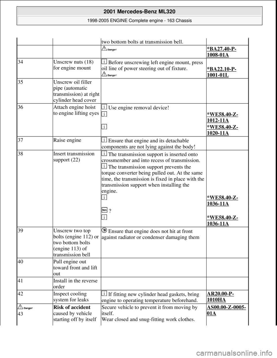
34Unscrew nuts (18)
for engine mount Before unscrewing left engine mount, press
oil line of power stee ring out of fixture.
*BA22.10-P-
1001-01L
35Unscrew oil filler
pipe (automatic
transmission) at right
cylinder head cover
36Attach engine hoist
to engine lifting eyes Use engine removal device!
*WE58.40-Z-
1012-11A
*WE58.40-Z-
1020-11A
37Raise engine Ensure that engine and its detachable
components are not lying against the body!
38Insert transmission
support (22) The transmission support is inserted onto
crossmember and into recess of transmission.
The transmission support prevents the
torque converter being pulled out. At the same
time, the transmission is fixed in place with the
transmission support when installing the
engine.
*WE58.40-Z-
1036-11A
?
*WE58.40-Z-
1036-11A
39Unscrew two top
bolts (engine 112) or
two bottom bolts
(engine 113) of
transmission bell Ensure that engine does not hit at front
against radiator or condenser damaging them
40Pull engine out
toward front and lift
out
41Install in the reverse
order
42Inspect cooling
system for leaks If fitting new cylinder head gaskets, bring
engine to operating temperature beforehand.AR20.00-P-
1010HA
43Risk of accident
caused by vehicle
starting off by itself Secure vehicle to prev ent it from moving by
itself.
Wear closed and snug-fitting work clothes. AS00.00-Z-0005-
01A
2001 Mercedes-Benz ML320
1998-2005 ENGINE Complete engine - 163 Chassis
me
Saturday, October 02, 2010 3:17:56 PMPage 57 © 2006 Mitchell Repair Information Company, LLC.