1997 MERCEDES-BENZ ML320 automatic transmission
[x] Cancel search: automatic transmissionPage 1487 of 4133
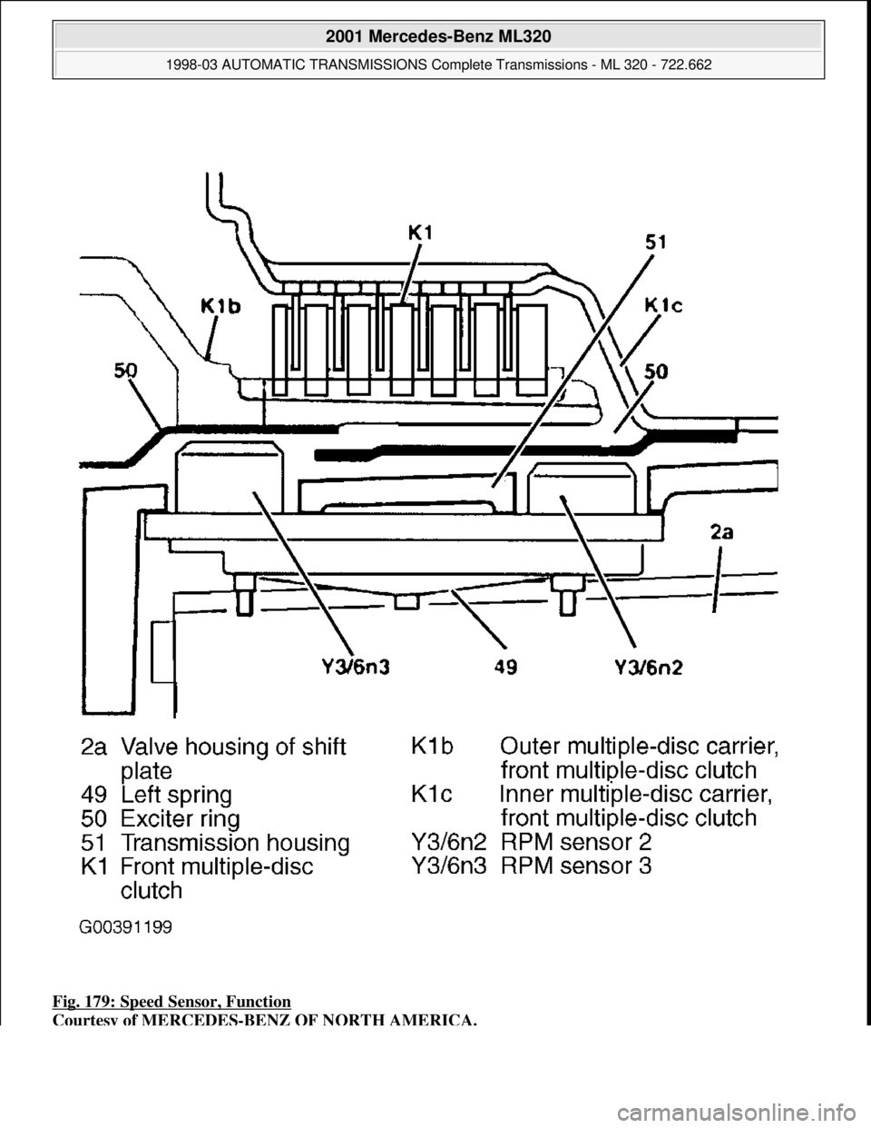
Fig. 179: Speed Sensor, Function
Courtesy of MERCEDES-BENZ OF NORTH AMERICA.
2001 Mercedes-Benz ML320
1998-03 AUTOMATIC TRANSMI SSIONS Complete Transmissions - ML 320 - 722.662
me
Saturday, October 02, 2010 3:15:30 PMPage 318 © 2006 Mitchell Repair Information Company, LLC.
Page 1488 of 4133

Operation
The RPM sensors are pressed against the transmission housing (51) by a spring (49) which is held against the
valve housing of the shift plate (2a). See .Fig. 179
This ensures a defined distance between the RPM sensors
and the exciter ring (50). RPM sensor 2 (Y3/6yn2) records the speed of the front planetary gear carrier via the
inner multiple-disc carrier of the front multiple-disc clutch (K1c).
2001 Mercedes-Benz ML320
1998-03 AUTOMATIC TRANSMISSIONS Complete Transmissions - ML 320 - 722.662
me
Saturday, October 02, 2010 3:15:30 PMPage 319 © 2006 Mitchell Repair Information Company, LLC.
Page 1567 of 4133
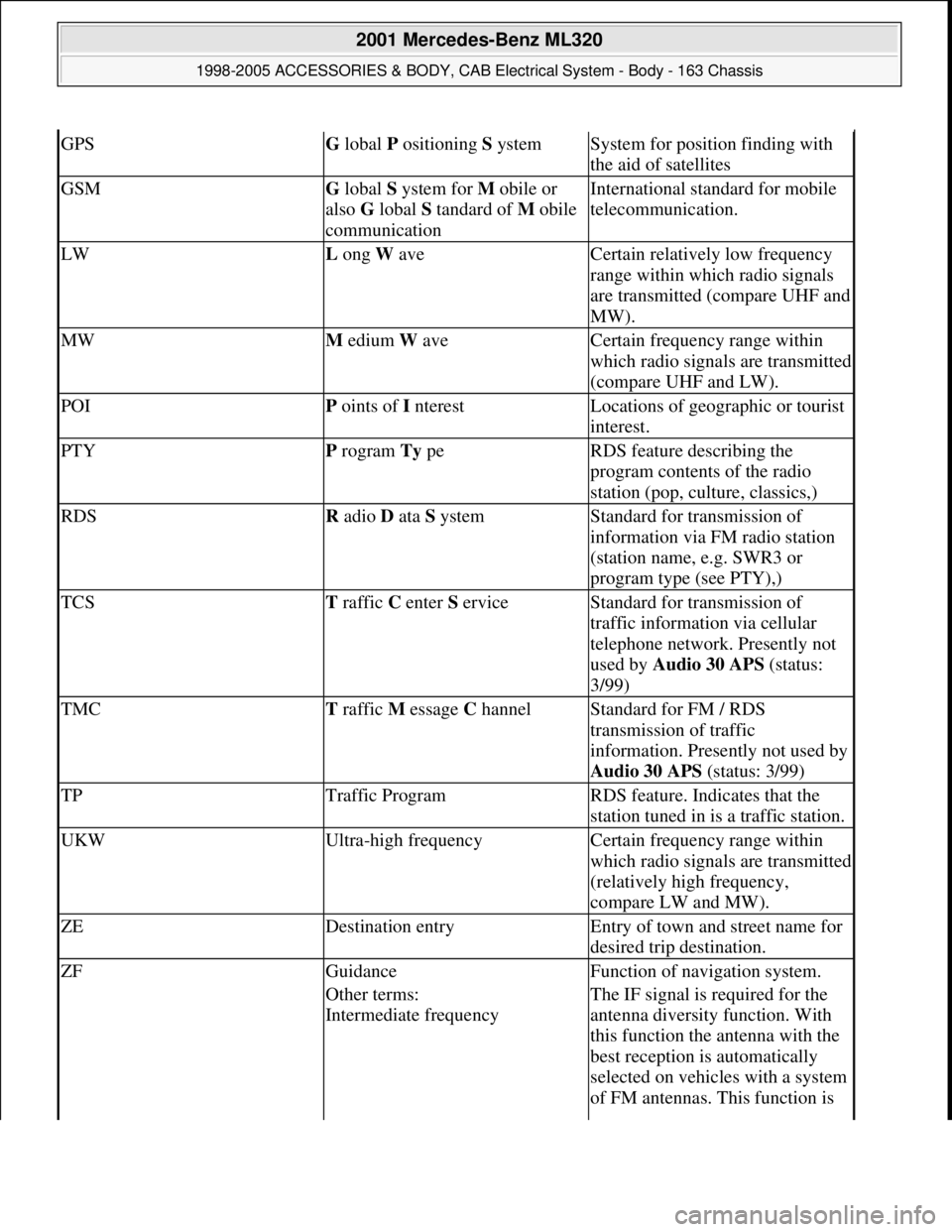
GPSG lobal P ositioning S ystemSystem for position finding with
the aid of satellites
GSMG lobal S ystem for M obile or
also G lobal S tandard of M obile
communicationInternational standard for mobile
telecommunication.
LWL ong W aveCertain relatively low frequency
range within which radio signals
are transmitted (compare UHF and
MW).
MWM edium W aveCertain frequency range within
which radio signals are transmitted
(compare UHF and LW).
POIP oints of I nterestLocations of geographic or tourist
interest.
PTYP rogram Ty peRDS feature describing the
program contents of the radio
station (pop, culture, classics,)
RDSR adio D ata S ystemStandard for transmission of
information via FM radio station
(station name, e.g. SWR3 or
program type (see PTY),)
TCST raffic C enter S erviceStandard for transmission of
traffic information via cellular
telephone network. Presently not
used by Audio 30 APS (status:
3/99)
TMCT raffic M essage C hannelStandard for FM / RDS
transmission of traffic
information. Presently not used by
Audio 30 APS (status: 3/99)
TPTraffic ProgramRDS feature. Indicates that the
station tuned in is a traffic station.
UKWUltra-high frequencyCertain frequency range within
which radio signals are transmitted
(relatively high frequency,
compare LW and MW).
ZEDestination entryEntry of town and street name for
desired trip destination.
ZFGuidanceFunction of navigation system.
Other terms:
Intermediate frequencyThe IF signal is required for the
antenna diversity function. With
this function the antenna with the
best reception is automatically
selected on vehicles with a system
of FM antennas. This function is
2001 Mercedes-Benz ML320
1998-2005 ACCESSORIES & BODY, CAB Electrical System - Body - 163 Chassis
me
Saturday, October 02, 2010 3:30:05 PMPage 72 © 2006 Mitchell Repair Information Company, LLC.
Page 1580 of 4133
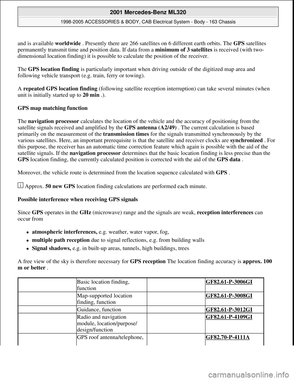
and is available worldwide . Presently there are 266 satellites on 6 different earth orbits. The GPSsatellites
permanently transmit time and position data. If data from a minimum of 3 satellites is received (with two-
dimensional location finding) it is possible to calculate the position of the receiver.
The GPS location finding is particularly important when driving outside of the digitized map area and
following vehicle transport (e.g. train, ferry or towing).
A repeated GPS location finding (following satellite reception interruption) can take several minutes (when
unit is initially started up to 20 min .).
GPS map matching function
The navigation processor calculates the location of the vehicle and the accuracy of positioning from the
satellite signals received and amplified by the GPS antenna (A2/49) . The current calculation is based
primarily on the measurement of the transmission times for the signals transmitted synchronously by the
various satellites. Here, an important prerequisite is that the satellite and receiver clocks are synchronized . For
this purpose, the receiver has an automatic time correction feature which again is possible with the aid of the
satellite signals. If the navigation processor determines that the basic location finding is less precise than the
GPS location finding, the currently calculated position is corrected with the aid of the GPS data .
Moreover, the vehicle route is determined from the location sequence calculated with GPS .
Approx. 50 new GPS location finding calculations are performed each minute.
Possible interference when receiving GPS signals
Since GPS operates in the GHz (microwave) range and the signals are weak, reception interferences can
occur from
atmospheric interferences, e.g. weather, water vapor, fog,
multiple path reception due to signal reflections, e.g. from building walls
Signal shadows, e.g. in built-up areas, tunnels, high buildings, trees
A free view of the sky is therefore necessary for GPS reception The location finding accuracy is approx. 100
m or better .
Basic location finding,
function GF82.61-P-3006GI
Map-supported location
finding, function GF82.61-P-3008GI
Guidance, function GF82.61-P-3012GI
Radio and navigation
module, location/purpose/
design/function GF82.61-P-4109GI
GPS roof antenna/telephone, GF82.70-P-4111A
2001 Mercedes-Benz ML320
1998-2005 ACCESSORIES & BODY, CAB Electrical System - Body - 163 Chassis
me
Saturday, October 02, 2010 3:30:05 PMPage 85 © 2006 Mitchell Repair Information Company, LLC.
Page 1592 of 4133
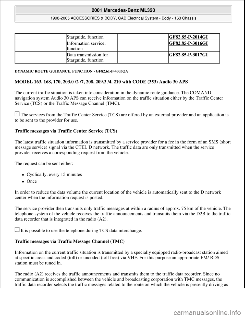
DYNAMIC ROUTE GUIDANCE, FUNCTION - GF82.61-P-4003QA
MODEL 163, 168, 170, 203.0 /2 /7, 208, 209.3 /4, 210 with CODE (353) Audio 30 APS
The current traffic situation is taken into consideration in the dynamic route guidance. The COMAND
navigation system Audio 30 APS can receive information on the traffic situation either by the Traffic Center
Service (TCS) or the Traffic Message Channel (TMC).
The services from the Traffic Center Service (TCS) are offered by an external provider and an application is
to be sent to the provider for use.
Traffic messages via Traffic Center Service (TCS)
The latest traffic situation information is transmitted by a service provider for a fee in the form of an SMS (short
message service) signal via the CTEL D network. The traffic data are only transmitted when the service
provider receives a corresponding request from the vehicle.
The request can be sent either:
Cyclically, every 15 minutes
Once
In order to reduce the data volume the current location of the vehicle is automatically sent to the D network
center when the information request is posted.
The service provider then transmits only traffic messages at within a radius of approx. 75 km of the vehicle. The
telephone system of the vehicle receives the traffic announcements and transmits them via the D2B to the traffic
data recorder that is integrated in the radio (A2).
It is possible to use the telephone during TCS data interchange.
Traffic messages via Traffic Message Channel (TMC)
Information on the current traffic situation is transmitted by a specially equipped radio-broadcast station aimed
at specific areas and coded (toll) or uncoded (toll free) via VHF. For this purpose an appropriate FM/ RDS
station must be tuned in.
The radio (A2) receives the traffic announcements and transmits them to the traffic data recorder. Since no
communication is accomplished between the vehicle and broadcasting corporation with TMC messages, the
traffic data recorder selects the traffic messa
ges related to the route on which the vehicle is presently driving as
Starguide, function GF82.85-P-2014GI
Information service,
function GF82.85-P-3016GI
Data transmission for
Starguide, function GF82.85-P-3017GI
2001 Mercedes-Benz ML320
1998-2005 ACCESSORIES & BODY, CAB Electrical System - Body - 163 Chassis
me
Saturday, October 02, 2010 3:30:05 PMPage 97 © 2006 Mitchell Repair Information Company, LLC.
Page 1810 of 4133
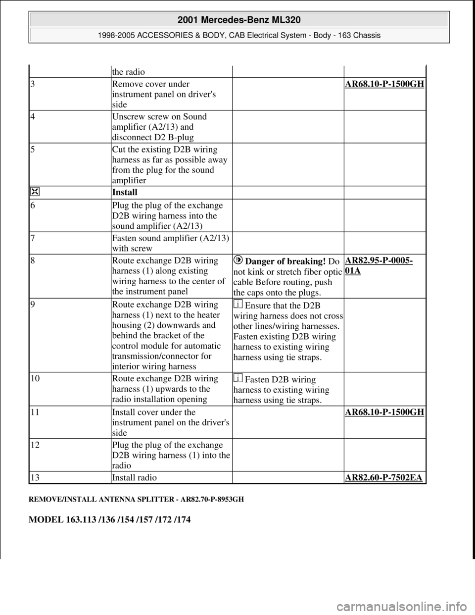
REMOVE/INSTALL ANTENNA SPLITTER - AR82.70-P-8953GH
MODEL 163.113 /136 /154 /157 /172 /174
the radio
3Remove cover under
instrument panel on driver's
side AR68.10-P-1500GH
4Unscrew screw on Sound
amplifier (A2/13) and
disconnect D2 B-plug
5Cut the existing D2B wiring
harness as far as possible away
from the plug for the sound
amplifier
Install
6Plug the plug of the exchange
D2B wiring harness into the
sound amplifier (A2/13)
7Fasten sound amplifier (A2/13)
with screw
8Route exchange D2B wiring
harness (1) along existing
wiring harness to the center of
the instrument panel Danger of breaking! Do
not kink or stretch fiber optic
cable Before routing, push
the caps onto the plugs.AR82.95-P-0005-
01A
9Route exchange D2B wiring
harness (1) next to the heater
housing (2) downwards and
behind the bracket of the
control module for automatic
transmission/connector for
interior wiring harness Ensure that the D2B
wiring harness does not cross
other lines/wiring harnesses.
Fasten existing D2B wiring
harness to existing wiring
harness using tie straps.
10Route exchange D2B wiring
harness (1) upwards to the
radio installation opening Fasten D2B wiring
harness to existing wiring
harness using tie straps.
11Install cover under the
instrument panel on the driver's
side AR68.10-P-1500GH
12Plug the plug of the exchange
D2B wiring harness (1) into the
radio
13Install radio AR82.60-P-7502EA
2001 Mercedes-Benz ML320
1998-2005 ACCESSORIES & BODY, CAB Electrical System - Body - 163 Chassis
me
Saturday, October 02, 2010 3:30:10 PMPage 315 © 2006 Mitchell Repair Information Company, LLC.
Page 1821 of 4133
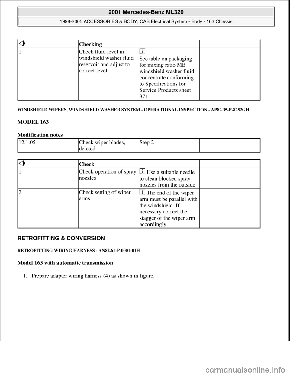
WINDSHIELD WIPERS, WINDSHIELD WASHER SYSTEM - OPERATIONAL INSPECTION - AP82.35-P-8252GH
MODEL 163
Modification notes
RETROFITTING & CONVERSION
RETROFITTING WIRING HARNESS - AN82.61-P-0001-01H
Model 163 with automatic transmission
1. Prepare adapter wirin
g harness (4) as shown in figure.
Checking
1Check fluid level in
windshield washer fluid
reservoir and adjust to
correct level
See table on packaging
for mixing ratio MB
windshield washer fluid
concentrate conforming
to Specifications for
Service Products sheet
371.
12.1.05Check wiper blades,
deletedStep 2
Check
1Check operation of spray
nozzles Use a suitable needle
to clean blocked spray
nozzles from the outside
2Check setting of wiper
arms The end of the wiper
arm must be parallel with
the windshield. If
necessary correct the
stagger of the wiper arm
accordingly.
2001 Mercedes-Benz ML320
1998-2005 ACCESSORIES & BODY, CAB Electrical System - Body - 163 Chassis
me
Saturday, October 02, 2010 3:30:10 PMPage 326 © 2006 Mitchell Repair Information Company, LLC.
Page 1828 of 4133
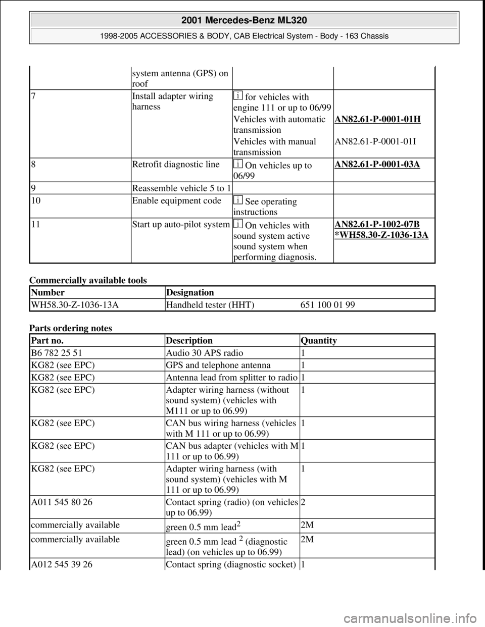
Commercially available tools
Parts ordering notes
system antenna (GPS) on
roof
7Install adapter wiring
harness for vehicles with
engine 111 or up to 06/99
Vehicles with automatic
transmissionAN82.61-P-0001-01H
Vehicles with manual
transmissionAN82.61-P-0001-01I
8Retrofit diagnostic line On vehicles up to
06/99AN82.61-P-0001-03A
9Reassemble vehicle 5 to 1
10Enable equipment code See operating
instructions
11Start up auto-pilot system On vehicles with
sound system active
sound system when
performing diagnosis.AN82.61-P-1002-07B
*WH58.30
-Z-1036-13A
NumberDesignation
WH58.30-Z-1036-13AHandheld tester (HHT)651 100 01 99
Part no.DescriptionQuantity
B6 782 25 51Audio 30 APS radio1
KG82 (see EPC)GPS and telephone antenna1
KG82 (see EPC)Antenna lead from splitter to radio1
KG82 (see EPC)Adapter wiring harness (without
sound system) (vehicles with
M111 or up to 06.99)1
KG82 (see EPC)CAN bus wiring harness (vehicles
with M 111 or up to 06.99)1
KG82 (see EPC)CAN bus adapter (vehicles with M
111 or up to 06.99)1
KG82 (see EPC)Adapter wiring harness (with
sound system) (vehicles with M
111 or up to 06.99)1
A011 545 80 26Contact spring (radio) (on vehicles
up to 06.99)2
commercially availablegreen 0.5 mm lead2 2M
commercially availablegreen 0.5 mm lead 2 (diagnostic
lead) (on vehicles up to 06.99)2M
A012 545 39 26Contact spring (diagnostic socket) 1
2001 Mercedes-Benz ML320
1998-2005 ACCESSORIES & BODY, CAB Electrical System - Body - 163 Chassis
me
Saturday, October 02, 2010 3:30:10 PMPage 333 © 2006 Mitchell Repair Information Company, LLC.