1997 MERCEDES-BENZ ML320 automatic transmission
[x] Cancel search: automatic transmissionPage 3436 of 4133

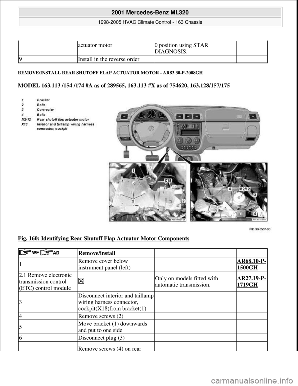
REMOVE/INSTALL REAR SHUTOFF FLAP ACTUATOR MOTOR - AR83.30-P-2008GH
MODEL 163.113 /154 /174 #A as of 289565, 163.113 #X as of 754620, 163.128/157/175
Fig. 160: Identifying Rear Shutoff Flap Actuator Motor Components
actuator motor0 position using STAR
DIAGNOSIS.
9Install in the reverse order
Remove/install
1Remove cover below
instrument panel (left) AR68.10-P-
1500GH
2.1 Remove electronic
transmission control
(ETC) control module
Only on models fitted with
automatic transmission.AR27.19-P-
1719GH
3
Disconnect interior and taillamp
wiring harness connector,
cockpit(X18)from bracket(1)
4Remove screws (2)
5Move bracket (1) downwards
and put to one side
6Disconnect plug (3)
Remove screws (4) on rear
2001 Mercedes-Benz ML320
1998-2005 HVAC Climate Control - 163 Chassis
me
Saturday, October 02, 2010 3:23:18 PMPage 192 © 2006 Mitchell Repair Information Company, LLC.
Page 3479 of 4133

BT27.00-Z-9999AZ
Technical modifications: Passenger cars: Automatic transmission
30.4.97
MODEL all
Vacuum unit for modulating pressure modified
TRANSMISSION 722.3 /5 as of 15.8.92
BT27.10-P-0001-01A
Secondary pump dispensed with
TRANSMISSION 722.5## ## as of 3652931
BT27.10-P-0002-01A
Control pressure cable with vacuum actuators
standardized
TRANSMISSION 722.3 /4 /5 as of 1.7.93
BT27.10-P-0003-01A
Sump volume modified
TRANSMISSION 722.7## ## as of 0054011
as of 29.7.99
BT27.10-P-0004-01A
Additional shim between deep-groove ball
bearing and output flange
TRANSMISSION 722 ...
BT27.10-P-0005-01A
Oil pan and overflow tube modified
TRANSMISSION 722.901
BT27.10-P-0006-01W
Retaining lug added to electrohydraulic
control module
TRANSMISSION 722.6## # as of 0026195
BT27.19-P-0001-01A
Caps for solenoid valve, new
TRANSMISSION 722.6 as of 1.8.97
BT27.19-P-0003-01A
Oil drain plug on torque converter deleted
TRANSMISSION 722.6## /6## ## as of
1772285 as of 22.9.99
BT27.20-P-0001-01A
Small intermediate plate modified
TRANSMISSION 722.5## ## as of 3987361
as of 15.3.94
BT27.35-P-0001-01A
Installation of a pressure feed valve
TRANSMISSION 722.6## # as of 0027083
BT27.35-P-0002-01A
Primary pump non-return valve dispensed with
TRANSMISSION 722.5## ## as of 3652931
BT27.35-P-0003-01A
Strainer for modulating pressure and shift
pressure control solenoid valve, new
TRANSMISSION 722.6## ## as of 0538312
BT27.35-P-0004-01A
Strainer in inlet to converter lock-up control
solenoid valve, newTRANSMISSION 722.6## ## as of 0485895
BT27.35-P-0005-01A
Feed B1 enlarged
TRANSMISSION 722.5 as of 15.8.91
BT27.40-P-0001-01A
Fluid reservoir deleted
TRANSMISSION 722.7## ## as of 0111673
as of 11.9.00
BT27.40-P-0002-01A
Magnet in oil pan, new part
TRANSMISSION 722.6## ## as of 2871384
as of 17.4.01, 722.7## ## as of 0153700 as
of 9.7.01
BT27.40-P-0003-01A
Piston B1 modified
TRANSMISSION 722.5## ## as of 3746852
as of 15.6.92, 722.3## ## as of 3969172
BT27.50-P-0002-01A
Plain bearing of input shaft changed to an anti-
friction bearing
TRANSMISSION 722 ...
BT27.50-P-0002-02A
One-way valve dispensed with
TRANSMISSION 722.5## ## as of 3652931
BT27.50-P-0007-01A
Outer multiple-disc carrier B1 modified
TRANSMISSION 722.6## # as of 0005900
BT27.50-P-0008-01A
Peak-to-valley height on piston B2 modified
TRANSMISSION 722.6## # as of 0023104
BT27.50-P-0009-01A
Piston B2 changed
TRANSMISSION 722.6## ## as of 0552036
as of 1.8.97
BT27.50-P-0010-01A
Friction bearing in sun wheel of rear planet
gear set converted to anti-friction bearing
TRANSMISSION 722 ...
BT27.50-P-0011-01A
Conversion from 18° to 23° gearing in front
and rear planetary gear system
TRANSMISSION 722 ...
BT27.50-P-0012-01A
Multi-disks for B1, K1 and K3 changed
TRANSMISSION 722.6## ## as of 3947440
as of 2.9.02
BT27.50-P-0013-01A
Thickness of friction and steel disks K3
changed
TRANSMISSION 722.6
BT27.51-P-0001-01A
Thickness of steel plates of B1, K1 and K2
modified
TRANSMISSION 722.6## ## as of 1596205
as of 15.6.99
BT27.51-P-0002-01A
Additional dished washer in multi-plate set K2
TRANSMISSION 722.6## ## as of 1596205
as of 15.6.99
BT27.51-P-0003-01A
Center shift modified
TRANSMISSION 722.6
BT27.60-P-0001-01A
Deletion shift lock cable ignition lock to
transmission
TRANSMISSION 722.7 in MODEL
WDB168.### ## as of 548031 as of 10.1.01
BT27.60-P-0001-02A
Selector lever soldered
TRANSMISSION 722.6 as of 1.5.96
BT27.60-P-0002-01A
Deletion of lever for shift lock cable ignition
lock at transmission
TRANSMISSION 722.700 ## as of 0129631
as of 24.1.01, 722.701 ## as of 0132072 as
of 8.2.01
BT27.60-P-0003-01A
Copyright DaimlerChrysler AG 28.05.2006 CD-Ausgabe G/10/04 . This WIS print-out will not be recorde
d by Modification services.
Page 1
Page 3523 of 4133

AUTOMATIC DIMMING INSIDE REARVIEW MIRROR, FUNCTION - GF68.49-P-0003GH
MODEL 163 as of 1.9.99 with CODE (249b) Automatic dimming inside rearview and outside rearview
mirror (driver)
Function requirements
No overvoltage or undervoltage
Term. 15R or 15 ON
Reverse gear not engaged
Interior lighting not switched on
Function
The glass of the inside rearview mirror (A67) can be electro-chromatically dimmed. The mirror glass between
the reflector and the glass cover contains a layer of electrolyte gel. The light transmission ratio of this gel
changes when a voltage is applied to it.
The light hitting the surface of the mirror is more or less reflected due to the variable of the actuation voltage.
The actuation voltage is controlled by the electronic circuitry in the inside rearview mirror. This is
accomplished depending on the ambient light and the light hitting the mirror.
The two input parameters are detected by the mirror dimming to rear sensor (A67h2) in the mirror housing
(rear) and by the mirror dimming forward sensor (A67h1) in the mirror glass of the inside rearview mirror
(A67).
The inside rearview mirror unit (A67) also acts as the master for the outside mirror dimming function
(driver's side).
CONTENTS - FUNCTION DESCRIPTION, AUTOMATIC DIMMING INSIDE REARVIEW MIRROR - GF68.49-P-0999GH
MODEL 163 as of 1.9.99 with CODE (249a) Automatic dimming inside rearview mirror
TROUBLE DIAGNOSIS
FRONT ASHTRAY DOES NOT OPEN SOFTLY OR IS STUCK - AF68.20-P-6000A
Garage door opener transmitter, location/ purpose GF68.05-P-1100A
Contents, function description of garage door opener GF68.05-P-0999A
Automatically dimming driver-side outside mirror, function GF88.79-P-2003GH
Function description, automatic dimming inside rearview mirror GF68.49-P-0003GH
Automatic dimming outside rearview mirror on driver's side, function GF88.79-P-2003GH
2001 Mercedes-Benz ML320
1998-2005 ACCESSORIES & BODY, CAB Interior Equipment - 163 Chassis
me
Saturday, October 02, 2010 3:35:21 PMPage 5 © 2006 Mitchell Repair Information Company, LLC.
Page 3715 of 4133

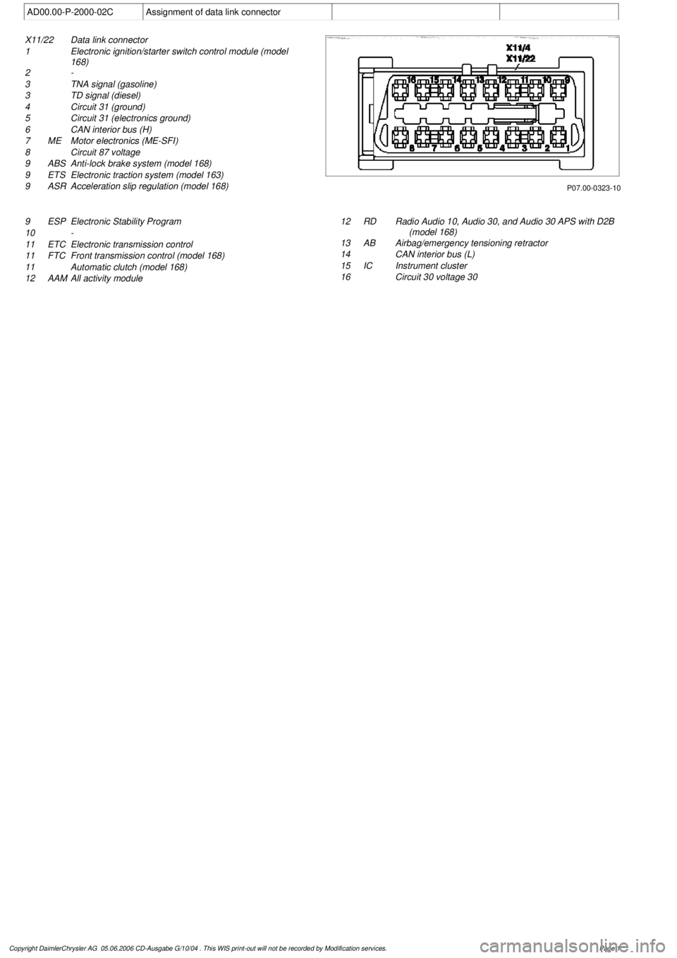
AD00.00-P-2000-02C
Assignment of data link connector
P07.00-0323-10
X11/22
Data link connector
1
Electronic ignition/starter switch control module (model
168)
2 -
3
TNA signal (gasoline)
3
TD signal (diesel)
4
Circuit 31 (ground)
5
Circuit 31 (electronics ground)
6
CAN interior bus (H)
7
ME
Motor electronics (ME-SFI)
8
Circuit 87 voltage
9
ABS
Anti-lock brake system (model 168)
9
ETS
Electronic traction system (model 163)
9
ASR
Acceleration slip regulation (model 168)
9
ESP
Electronic Stability Program
10
-
11 ETC
Electronic transmission control
11
FTC
Front transmission control (model 168)
11
Automatic clutch (model 168)
12
AAM
All activity module
12
RD
Radio Audio 10, Audio 30, and Audio 30 APS with D2B
(model 168)
13
AB
Airbag/emergency tensioning retractor
14
CAN interior bus (L)
15 IC
Instrument cluster
16
Circuit 30 voltage 30
Copyright DaimlerChrysler AG 05.06.2006 CD-Ausgabe G/10/04 . This WIS print-out will not be recorde
d by Modification services.
Page 1
Page 3745 of 4133

2.1
Detach automatic transmission from engine
Models 463.206/ 209/ 232/ 233/ 240/ 241
AR27.10-P-0500BD
Models 463.243/ 244/ 245/ 246/ 247/ 248/
249/ 250/ 254
AR27.10-P-0500GA
Model 230.475
AR27.10-P-0500R
Model 230.474
Model 220 without 4MATIC
AR27.10-P-0500I
Model 220 with 4MATIC
AR27.10-P-0500IW
Models 129, 170, 202, 208, 210
AR27.10-P-0500B
Model 203 without 4MATIC, 209 with Engine
112,113
AR27.10-P-0500P
Model 203 with 4MATIC
AR27.10-P-0500PW
Model 211.061/065/070
AR27.10-P-0500T
Model 163
AR27.10-P-0500GH
2.2
Detach manual transmission from engine
Models 129, 202, 210
AR26.10-P-0020A
Models 203, 209 with Engine 112
AR26.10-P-0020P
Model 211.061
AR26.10-P-0020T
Model 208 with transmission 716.662/622
AR26.10-P-0020E
Model 170,
Model 208 with transmission 716.663
AR26.10-P-0020D
3
Detach top part of oil pan
Models 463.206/ 209/ 232/ 233/ 240/ 241/
243/ 244/ 245/ 246/ 247/ 248/ 249/ 250/ 254
AR01.45-P-7500FG
Model 230.474/
AR01.45-P-7500R
Model 220 without 4MATIC
AR01.45-P-7500I
Model 220 with 4MATIC
AR01.45-P-7500IW
Model 210 with 4MATIC
AR01.45-P-7500FA
Model 210 without 4MATIC
AR01.45-P-7500F
Models 202, 208
AR01.45-P-7500FC
Model 203 without 4MATIC, 209 with Engine
112,113
AR01.45-P-7500PV
Model 203 with 4MATIC
AR01.45-P-7500PW
Models 211.061/065/070
AR01.45-P-7500TV
Model 170
AR01.45-P-7500SV
Model 163
AR01.45-P-7500FB
Model 129
AR01.45-P-7500FD
4
Take off cylinder head
Remove intake manifold with complete
wiring loom during this step.
Models 463.206/ 209/ 232/ 233/ 240/ 241/
243/ 244/ 245/ 246/ 247/ 248/ 249/ 250/ 254
AR01.30-P-5800GV
Engine 112 in model 129 and engine 113 in
models 129, 202, 208, 210
AR01.30-P-5800B
Engine 112 in models 170, 202, 208, 210,
220 and engine 113 in models 220,
230.474 /475
AR01.30-P-5800BA
Model 163
AR01.30-P-5800MV
Models 203, 209 with engine 112, 113
Models 211.061/065/070
AR01.30-P-5800PV
5
Remove oil pump
Push back chain tensioner for this step
and take off chain.
All except models 203, 209, 211.061/065/070,
220 without 4MATIC, 230.474 /475
AR18.10-P-6020B
Model 203 without 4MATIC, 209,
211.061/065/070
AR18.10-P-6020PV
Model 203 with 4MATIC, model 220 with
4MATIC
AR18.10-P-6020PW
Model 230.474/475
AR18.10-P-6020R
6
Remove conrod bearing cap (5)
For this step, mark conrod (4) and
connecting rod bearing cap (5) on one side
relative to each other.
7
Remove conrod (4) together with pistons (3)
by lifting up and out
If pistons have been used (3), the arrows
indicating the direction of the travel and the
markings on the pistons may no longer be
visible due to carbon deposits. For this
reason, remove the carbon deposits from the
pistons. If the arrows indicating direction of
travel on the pistons are no longer
recognizable, these must be re-marked.
8
Remove circlip (1) of piston pin (2)
Do not damage piston (3). Place a clean
cloth underneath.
9
Press out piston pin (2)
Installing
10
Assign piston (3) to cylinder bore
AR03.10-P-7021-02BV
Copyright DaimlerChrysler AG 20.05.2006 CD-Ausgabe G/10/04 . This WIS print-out will not be recorde
d by Modification services.
Page 2
Page 3747 of 4133

25.1
Fit on automatic transmission
Models 463.206/ 209/ 232/ 233/ 240/ 241
AR27.10-P-0500BD
Models 463.243/ 244/ 245/ 246/ 247/ 248/
249/ 250/ 254
AR27.10-P-0500GA
Model 230.475
AR27.10-P-0500R
Model 230.474
Model 220 without 4MATIC
AR27.10-P-0500I
Model 220 with 4MATIC
AR27.10-P-0500IW
Models 210, 208, 202,170. 129
AR27.10-P-0500B
Model 203 without 4MATIC, 209 with engines
112,113
AR27.10-P-0500P
Model 203 with 4MATIC
AR27.10-P-0500PW
Models 211.061/065/070
AR27.10-P-0500T
Model 163
AR27.10-P-0500GH
25.2
Fit on manual transmission
Models 210, 202, 129
AR26.10-P-0020A
Models 203, 209 with engine 112
AR26.10-P-0020P
Model 211.061
AR26.10-P-0020T
Model 208 with transmissions 716.662/622
AR26.10-P-0020E
Model 170,
Model 208 with transmission 716.663
AR26.10-P-0020D
26
Install engine
Models 463.243/ 244/ 245/ 246/ 247/ 248/
249/ 250/ 254
AR01.10-P-2400CC
Model 230.475
AR01.10-P-2400R
Model 230.474
AR01.10-P-2400RVK
Model 220 without 4MATIC
AR01.10-P-2400AB
Model 220 with 4MATIC
AR01.10-P-2400IW
Model 210 with 4MATIC
AR01.10-P-2400C
Model 210 without 4MATIC, 208, 202, 129
AR01.10-P-2400CB
Model 203 without 4MATIC, 209 with engine
112
AR01.10-P-2400PV
Model 203 with 4MATIC
AR01.10-P-2400PW
Model 209 with engine 113
AR01.10-P-2400Q
Models 211.061/065/070
AR01.10-P-2400TC
Model 170
AR01.10-P-2400SV
Model 163
AR01.10-P-2400CA
Inspection data of conrod bolts
Number
Designation
Engine
112 except
112.951,
113.94/96/980/
981/982/984/986
Engine
113.992
BE03.10-P-1001-03A
Conrod bolts
Thread
4M8B18B1
Shank length
when new
mm
4742
max.
mm
47.642.6
Part no.
--
Designation
Engines
112 except
112.951,
113.940/941/
942/943/944/
945/946/948/
960/961/962/
963/965/966/
967/968/980/
981/982/984/
986/987/988/
990/991/992/
993
BA03.10-P-1001-01E
Connecting rod bolt
Stage 1
Nm
5
2nd stage
Nm
25
Copyright DaimlerChrysler AG 20.05.2006 CD-Ausgabe G/10/04 . This WIS print-out will not be recorde
d by Modification services.
Page 4
Page 3757 of 4133

3.1
Remove viscous fan (1)
Engine 112.942 /970 and 113.942.
Right-hand thread!
AR20.40-P-5660C
3.2
Remove electric fan
Only Engine 113.965 /981.
AR20.40-P-5000GH
4.1
Pull off plate clamps of fan shroud (2)
Only for Engine 112.942, from 5/98.
5.1
Remove fan shroud (3)
Only for Engine 112.942 /970 und
113.942. Unscrew the bolts at bottom of fan
shroud for this step
Installation:
If installing a new radiator
with integral power steering pump oil cooler, a
new fan shroud is required if a radiator
without integral oil cooler was previously
installed.
6
Remove headlamp (7).
AR82.10-P-4730GH
7
Remove radiator crossmember (8)
AR62.30-P-2300GH
8
Detach coolant line (4, 6) and expansion
reservoir coolant line (5) at the radiator
Installation:
Replace the hose clamps on
the radiator fitting for the coolant hose, as
they could cause damage to the screw/thread.
Hose clamp
*BA20.20-P-1004-01A
9
Remove the rubber seal on radiator (9)
10.1
Remove oil line (return line of radiator
!
power steering pump expansion reservoir)
(18) and oil line (feed line of steering gear
!
radiator) (19)
From 5/98 only, seal off the connections.
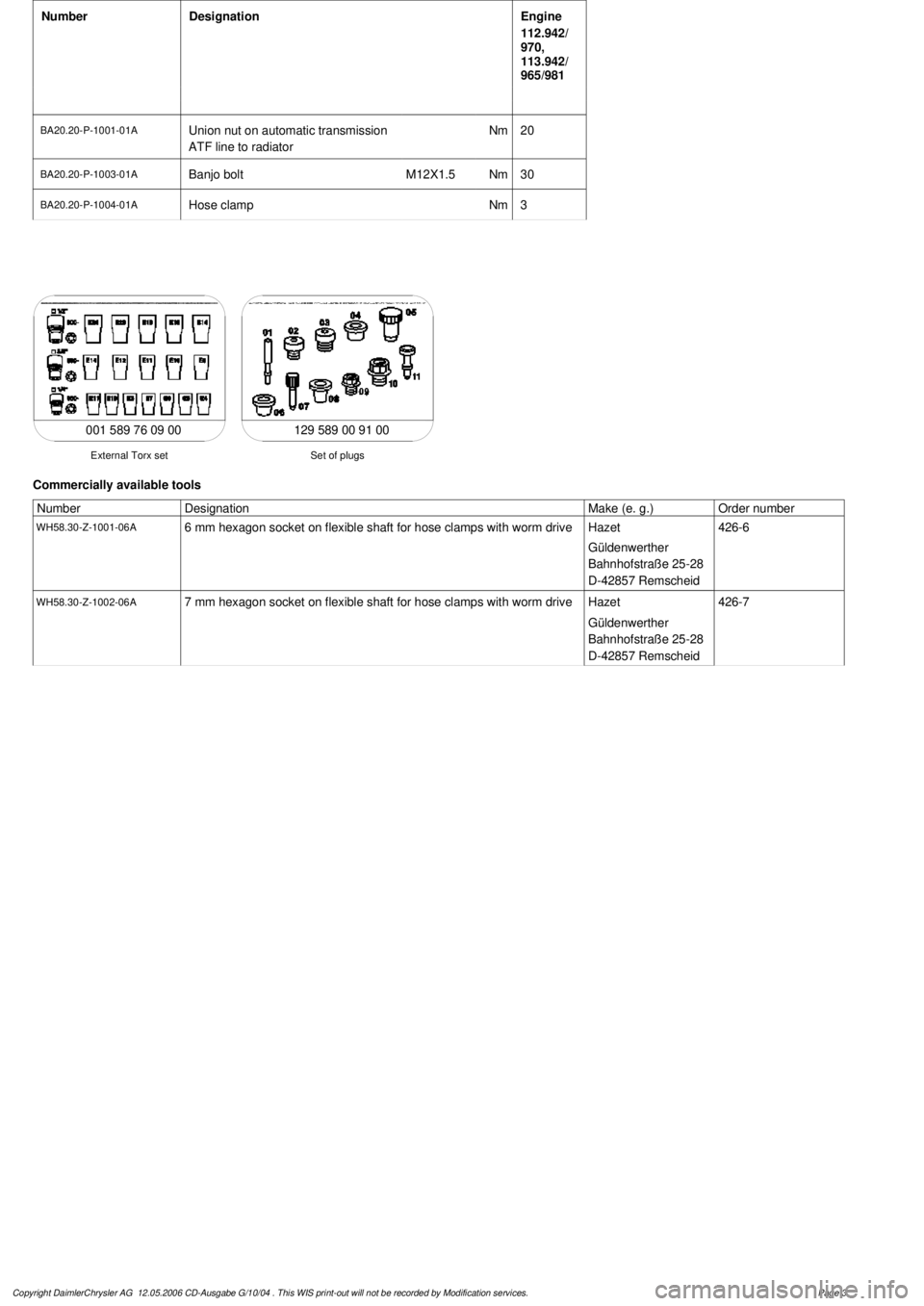
Set of plugs
*129589009100
11
Unscrew ATF lines (10) at the radiator
Seal off the connections.
*BA20.20-P-1001-01A
*BA20.20-P-1003-01A
Set of plugs
*129589009100
12.1
Detach the connector from the fan and
remove the fan grille (11)
Only for Engine 112.942 /970 and 113.942.
13
Unscrew the condenser from the radiator
Do not disconnect the lines.
14
Remove fasteners (20) and damper rubber
(21)
The damper rubber (21) is designed to
prevent possible vibrations between the
condenser and radiator (15) during off-road
driving.
15
Remove air conditioning system fluid
reservoir (14) from the radiator
Place aside with the lines connected.
Detach the condenser from the radiator.
16
Remove radiator (15)
When installing, the spigots on the
radiator must be inserted in the rubber
grommets in the bottom crossmember.
Installation:
On Model 163.154 with
Engine 112.942 before VIN end number
043553, when installing a new radiator with
integral power steering pump oil cooler,
additional operations are required, if they
have not already been carried out:
#
v
Retrofit the bracket for the oil cooler line of
the power steering pump
SM46.30-P-0002A
k
Radiator with integral oil cooler for the power
steering pump
BT20.20-P-0001-01A
17
Detach air guides (12)
Replace the clamps on air guides (13).
18
Install in the reverse order
19
Pour in coolant
AR20.00-P-1142HA
20
Check the headlamp setting and correct if
necessary
e
Check and adjust the headlamp setting
AP82.10-P-8260GH
Danger!
Risk of accident
caused by vehicle starting
off when engine is running.
Risk of injury
caused by contusions and burns when
working in engine during starting procedure
Secure the vehicle to prevent it from moving.
Wear closed and snug-fitting work clothes.
Do not grasp hot or rotating parts.
AS00.00-Z-0005-01A
21
Check the oil level in the automatic
transmission and correct if necessary
AR27.00-P-0101A
22
Check the cooling system for leaks
AR20.00-P-1010HA
Radiator, coolant hoses
Copyright DaimlerChrysler AG 12.05.2006 CD-Ausgabe G/10/04 . This WIS print-out will not be recorde
d by Modification services.
Page 2
Page 3758 of 4133

Number
Designation
Engine
112.942/
970,
113.942/
965/981
BA20.20-P-1001-01A
Union nut on automatic transmission
ATF line to radiatorNm
20
BA20.20-P-1003-01A
Banjo bolt
M12X1.5
Nm
30
BA20.20-P-1004-01A
Hose clamp
Nm
3
129 589 00 91 00
Set of plugs
External Torx set
001 589 76 09 00
Commercially available tools
Number
Designation
Make (e. g.)
Order number
WH58.30-Z-1001-06A
6 mm hexagon socket on flexible shaft for hose clamps with worm drive
Hazet
Güldenwerther
Bahnhofstraße 25-28
D-42857 Remscheid
426-6
WH58.30-Z-1002-06A
7 mm hexagon socket on flexible shaft for hose clamps with worm drive
Hazet
Güldenwerther
Bahnhofstraße 25-28
D-42857 Remscheid
426-7
Copyright DaimlerChrysler AG 12.05.2006 CD-Ausgabe G/10/04 . This WIS print-out will not be recorde
d by Modification services.
Page 3